1
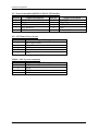
WEBS‐1012 Series / Atom FAN‐LESS System • Introduction 2 o Features o Package contents 2 2 • Hardware specifications 3 • System Board (NANO‐8045L Detail manual) 4 ~ Page 1 of 3
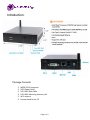
Introduction:
Package Contents:
1.
2.
3.
4.
5.
6.
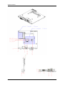
WEBS‐1012A computer SATA Power Cable SATA HDD Data Cable SATA HDD Mounting Accessory Kit WiFi antenna System Board Driver CD Page 2 of 3
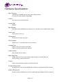
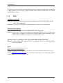
Hardware Specifications:
Main Processor On board Intel® ATOMTM Z510 (1.1GHz) / Z530 (1.6GHz) processor CPU clock bus: Z530: 533MHz / Z510:400MHz Chipset Intel® System Controller Hub US15W System BIOS AMI BIOS Main Memory One 200‐pin DDR2 SODIMM socket supports up to 2GB dual channel 400/533 MHz memory Power input DC 12V input on rear I/O USB Interface Two front & rear USB access ports SATA Interface Support one 2.5” SATA HDD / able to mount internally Compact Flash Support one Type II Compact Flash socket Audio Interface Rear I/O Audio Jack for Line‐Out Support boot from Compact Flash function Watch Dog Timer Support WDT function through software programming for enable/disable and interval setting / General system reset Display Support dual independent display by DVI and 24‐bit LVDS On board Ethernet LAN One Gigabit Ethernet (10/100/1000 Mbits/sec) LAN ports using Realtek 8111C Controller WLAN / Wireless LAN One 802.11 a/b/g VT6656 WLAN controller enables high‐speed 54Mbps wireless connections
Page 3 of 3
NANO-8045L
NANO-ITX Board
User's Manual
Version 1.0
Copyright © Portwell, Inc., 2009. All rights reserved.
All other brand names are registered trademarks of their respective owners.
Preface
Table of Contents
How to Use This Manual
Chapter 1 System Overview.......................................................................................................1-1
1.1 Introduction.................................................................................................................................. 1-1
1.2 Check List ..................................................................................................................................... 1-1
1.3 Product Specification .................................................................................................................. 1-2
1.3.1 Mechanical Drawing ......................................................................................................... 1-4
1.4 System Architecture .................................................................................................................... 1-6
Chapter 2 Hardware Configuration ...........................................................................................2-1
2.1 Jumper Setting.............................................................................................................................. 2-1
2.2 Connector Allocation .................................................................................................................. 2-3
Chapter 3 System Installation....................................................................................................3-1
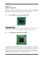
3.1 Intel ® ATOM TM processor Z510/Z530 CPU ........................................................................... 3-1
3.2 Intel® System Controller Hub US15W ..................................................................................... 3-1
3.3 Main Memory............................................................................................................................... 3-2
3.4 Installing the Single Board Computer ...................................................................................... 3-2
3.4.1 Chipset Component Driver.............................................................................................. 3-3
3.4.2 Intel Integrated Graphics GMCH Chip .......................................................................... 3-3
3.4.3 Realtek Gigabit Ethernet Controller................................................................................ 3-3
3.4.4 Audio Controller ............................................................................................................... 3-4
3.5 WDT Function.............................................................................................................................. 3-4
3.6 GPIO Function ............................................................................................................................. 3-7
3.6.1 Pin assignment................................................................................................................... 3-8
Chapter 4 BIOS Setup Information............................................................................................4-1
4.1 Entering Setup.............................................................................................................................. 4-1
4.2 Main Menu ................................................................................................................................... 4-2
4.3 Advanced...................................................................................................................................... 4-3
4.4 PCIPnP ........................................................................................................................................ 4-17
4.5 Boot.............................................................................................................................................. 4-19
4.6 Security ....................................................................................................................................... 4-23
4.7 Chipset ........................................................................................................................................ 4-24
4.8 Exit............................................................................................................................................... 4-29
Chapter 5 Troubleshooting ........................................................................................................5-1
5.1 Hardware Quick Installation ..................................................................................................... 5-1
5.2 BIOS Setting.................................................................................................................................. 5-1
5.3 FAQ ............................................................................................................................................... 5-3
Appendix A
Appendix B
Preface
How to Use This Manual
The manual describes how to configure your NANO-8045L system board to meet
various operating requirements. It is divided into five chapters, with each chapter
addressing a basic concept and operation of Single Host Board.
Chapter 1: System Overview. Presents what you have in the box and give you an
overview of the product specifications and basic system architecture for this series
model of single host board.
Chapter 2: Hardware Configuration. Show the definitions and locations of Jumpers
and Connectors that you can easily configure your system.
Chapter 3: System Installation. Describes how to properly mount the CPU, main
memory and Compact Flash to get a safe installation and provides a programming
guide of Watch Dog Timer function.
Chapter 4: BIOS Setup Information. Specifies the meaning of each setup parameters,
how to get advanced BIOS performance and update new BIOS. In addition, POST
checkpoint list will give users some guidelines of trouble-shooting.
Chapter 5: Troubleshooting. Provide various of useful tips to quickly get
NANO-8045L running with success. As basic hardware installation has been
addressed in Chapter 3, this chapter will basically focus on system integration issues,
in terms of backplane setup, BIOS setting, and OS diagnostics.
The content of this manual is subject to change without prior notice. These changes
will be incorporated in new editions of the document. The vendor may make
supplement or change in the products described in this document at any time.
System Overview
Chapter 1
System Overview
1.1
Introduction
Powell Inc., a world-leading innovator in the Industrial PC (IPC) market and a
member of the Intel® Communications Alliance, has launched its new NANO-8045L
in response to market demand for a simplified embedded system board (ESB) that
combines a smaller footprint, lower power consumption, robust computing power
and with longevity support.
The NANO-8045L is specifically designed to operate at very low power consumption
and low heat, so it can be a truly fanless configuration and battery operated. Base on
Intel® System Controller Hub US15W, the NANO-8045L supports one 200-pin
SO-DIMM memory slot for DDR2 SDRAM up to 2GB and comes with two SATA, one
Type II CompactFlash® socket, dual independent display by DVI and 24-bit LVDS,
one gigabit Ethernet, and six USB port (one port can support client USB). It also built
with DC 12V input. It’s a low profile type standard board. The rear I/O height is
lower than 20mm.
Base on leading Intel® Atom solution, NANO-8045L is a compact and ultra low
power dissipation board for Digital Signage, Digital Security Surveillance (DSS)
applications…etc.
1.2
Check List
The NANO-8045L package should cover the following basic items
One NANO-8045L NANO-ITX Main Board
One 2-in-1 Heatsink
One Installation Resources CD-Title
One SATA cable
One SATA power cable
If any of these items is damaged or missing, please contact your vendor and keep all
packing materials for future replacement and maintain.
NANO-8045L User’s Manual
1-1
System Overview
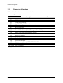
1.3
Product Specification
Main Processor
- On board Intel® ATOMTM Z510 (1.1GHz) / Z530 (1.6GHz) processor
- CPU clock bus: Z530: 533MHz / Z510:400MHz
Chipset
Intel® System Controller Hub US15W
System BIOS
AMI BIOS
Main Memory
One 200-pin DDR2 SODIMM socket supports up to 2GB dual channel 400/533
MHz memory
Power input
DC 12V input on rear I/O
USB Interface
Support six USB (Universal Serial Bus) ports, two on rear I/O and four on board
header for internal devices (one port can support client USB).
SATA Interface
Support two SATA II ports
Compact Flash
- Support one Type II Compact Flash socket
- Support boot from Compact Flash function
Audio Interface
- Rear I/O Audio Jack for Line-Out
- On-Board pin header for Mic-In and Line-Out
Watch Dog Timer
- Support WDT function through software programming for enable/disable and
interval setting
- General system reset
Display
Support dual independent display by DVI and 24-bit LVDS
On-board Ethernet LAN
- One Gigabit Ethernet (10/100/1000 Mbits/sec) LAN ports using Realtek
8111C PCI-Expressx1 interface GbE Ethernet Controller
- Support Wake on LAN function
High Drive GPIO
On-board programmable 8-bit Digital I/O interface
NANO-8045L User’s Manual
1-2
System Overview
Cooling Fans
Support one 3-pin power connector for system fan
System Monitoring Feature
Monitor system temperature and major power sources.
Outline Dimension (L x W)
120mm(4.72’’) x 120mm(4.72’’)
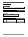
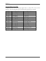
Power Requirements
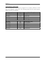
Configuration
CPU Type
SBC BIOS
Memory
Intel® Atom™ CPU Z530 1.60GHz FSB:533MHz L2:512K
Portwell, Inc. NANO-8045L series BIOS Rev.:R1.00.E0 (03122009)
Apacer DDR2 PC4300 512MB*1 (Samsung K4T51083QE-ZCD5)
VGA Card
Onboard Intel Corporation Poulsbo Embedded Graphics
Chipset Function 0
Intel Corporation Poulsbo Embedded Graphics Chipset
Onboard Realtek 8111C PCI-E Gigabit Network Connection
Realtek RTL8169C(P)/8111C PCI-E Gigabit Ethernet NIC
Onabord Realtek ALC262 High Definition Audio Controller
Realtek High Definition Audio Controller Version:5.10.0.5804
Intel® Chipset Device Software Version:8.8.0.1011
Intel® SCH Family USB2 Enhanced Host Controller
Version:8.8.0.1001
WDC WD1500ADFD-00NLR5
Apacer AP-CF128B-Steno
LITE-ON DVDRW LH-20A1S
Seasonic SSA-0651-1
VGA Driver
LAN Card
LAN Driver
Audio Card
Audio Driver
Chip Driver
USB 2.0 Driver
SATA HDD
Compact Flash
SATA CDROM
Power Supply
Item
Power ON
Full Loading 10Min
Full Loading 30Min
DC 12V
0.83A
1.39A
1.40
Operating Temperature
0 °C ~ 60 °C
Storage temperature
-20 ~ 80 °C
Relative Humidity
0% ~ 90%, non-condensing
NANO-8045L User’s Manual
1-3
System Overview
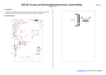
1.3.1
Mechanical Drawing
NANO-8045L User’s Manual
1-4
System Overview
NANO-8045L User’s Manual
1-5
System Overview
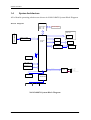
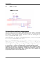
1.4
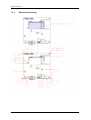
System Architecture
All of details operating relations are shown in NANO-8045L System Block Diagram.
Block Diagram
DC 12V input
DDR2 TERMINATOR
CPU BUS
Silverthone
Z510:1.1G
Z530:1.6G
SDVO-DVI
SDVO
DDR2 SO-DIMM
CHANNEL A
DDR2 CHA
SDVO-VGA
CH7307
24-bits LVDS
Poulsbo
US15W
DVI
LVDS
PCIEx1(1) bus
PCIEx1(2) bus
JMB362
SATA x 2
RJ-45:Giga-Lan
RTL8111C
IDE BUS
CF CONN
USB PORT x 2
Rear Panel
USB PORT x 4
Header
USB
USB
HD Audio
ALC262
Audio Jack
(Line-out)
Pin Header
(Line-out,Mic-in)
LPC BUS
SPI
W83627DHG
Fan x 1
GPIO
HW MONITOR
NANO-8045L System Block Diagram
NANO-8045L User’s Manual
1-6
Hardware Configuration
Chapter 2
Hardware Configuration
This chapter gives the definitions and shows the positions of jumpers, headers and
connector. All of the configuration jumpers on NANO-8045L are in the proper
position. The default settings are indicated with a star sign ( ).
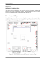
2.1
Jumper Setting
In the following sections, Short means covering a jumper cap over jumper pins; Open
or N/C (Not Connected) means removing a jumper cap from jumper pins. Users can
refer to Figure 2-1 for the Jumper allocations.
Figure 2-1 NANO-8045L Jumper and Connector Locations (Top)
NANO-8045L User’s Manual
2-1
Hardware Configuration
JP5 : 5V / 3.3Vbacklight Inverter Power selection
JP5
1-2 Short
2-3 Short
Signal Description
3.3V
5V
JP6 : LCD Power Jump Setting
JP6
1-2 Short
2-3 Short
Signal Description
3.3V
5V
JP4 : PM_SLPMODE Jumper
JP4
1-2 Short
Function
PM_SLPMODE connect
JP3 : SLP_S5 jumper
JP3
1-2 Short
Function
SLP_S5 Enable
JP2 : RSMRST# jumper
JP2
1-2 Short
Function
RSMRST# Enable
JP1 : LPC Debug Port header
PIN No.
1
3
5
7
Signal Description
LPC_AD0
LPC_AD1
LPC_AD2
LPC_AD3
NANO-8045L User’s Manual
PIN No.
2
4
6
8
10
Signal Description
VCC3
PLT_RST#
LPC_FRAME#
LPC_PCID
GND
2-2
Hardware Configuration
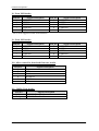
2.2
Connector Allocation
I/O peripheral devices are connected to the interface connectors
Connector Function List
Connector
J1
J22
J3
J23
J5
J6
J7
J8/J9
J10
J11
J13
J14
J15
J16
J17
J18
CN3/CN4
J20/J21
Description
Remark
DVI-D connector
12V DC-IN connector
COM port connector
Audio (LINE_OUT) Interface connector
USB connector
RJ-45 connector
Audio (LINE_OUT/MIC_IN) Interface header
Front USB header (*J8 port 2 support Client USB)
Micro-controller programming header
CMOS Clear header
DDR2 SO-DIMM
LVDS Interface
Fan header
8-bit GPIO header
Power button/Reset/HDD LED/SUS LED header
LVDS inverter header
SATA connector
SATA power connector
NANO-8045L User’s Manual
2-3
Hardware Configuration
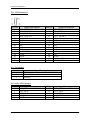
Pin Assignments of Connectors
J22 : 12V DC-IN connector
PIN No.
Green
Signal Description
LINE_OUT
PIN No.
Pink
Signal Description
MIC_IN
J4 : Audio (MIC_IN/LINE_OUT) Interface connector
PIN No.
Green
Signal Description
LINE_OUT
PIN No.
Pink
Signal Description
MIC_IN
J5 : USB connector
PIN No.
J5A
J5B
Signal Description
USB port4
USB port5
J7 : Audio (LINE_OUT/MIC_IN) Interface header
PIN No.
1
3
5
7
9
Signal Description
CN_MIC_IN_R
NC
NC
LINEOUT-L
LINEOUT-R
NANO-8045L User’s Manual
PIN No.
2
4
6
8
Signal Description
CN_MIC_IN_L
ACGND
ACGND
ACGND
2-4
Hardware Configuration
J8 : Front USB header
PIN No.
1
3
5
7
9
Signal Description
USB3VCC
USBD3USBD3+
USBGND
NC
PIN No.
2
4
6
8
10
Signal Description
USB2VCC
USBD2USBD2+
USBGND
NC
PIN No.
2
4
6
8
10
Signal Description
USB0VCC
USBD0USBD0+
USBGND
NC
* Pin 2.4.6.8 support Client-USB function
J9 : Front USB header
PIN No.
1
3
5
7
9
Signal Description
USB1VCC
USBD1USBD1+
USBGND
NC
J10 : Micro-controller download firmware header
PIN No.
1
2
3
4
5
6
Signal Description
Vpp
Vdd
Gnd
ICSPDAT
ICSPCLK
NC
J11 : CMOS Clear header
PIN No.
1-2 Short
1-2 Open
Signal Description
CMOS Clear disable CMOS Clear Enable
NANO-8045L User’s Manual
2-5
Hardware Configuration
J14 : LVDS Interface
PIN No.
1
3
5
7
9
11
13
15
17
19
21
23
25
27
29
Signal Description
Ch1_DATA0+
Ch1_ DATA 1+
Ch1_ DATA2+
Ch1_ DATA 3+
Ch1_ CLK+
NC
NC
NC
NC
NC
L_BKLTCTL
GND
GND
VDD_LVDS
N/A
PIN No.
2
4
6
8
10
12
14
16
18
20
22
24
26
28
30
Signal Description
Ch1_ DATA 0Ch1_ DATA 1Ch1_DATA2Ch1_ DATA 3Ch1_ CLKNC
NC
NC
NC
NC
NC
NC
GND
VDD_LVDS
VDD_LVDS
J15 : Fan header
PIN No.
1
2
3
Signal Description
GND
FANPWM1
FANI01
J16 : 8-bits GPIO header
PIN No.
1
3
5
7
9
Signal Description
LPC_GP10
LPC_GP11
LPC_GP12
LPC_GP13
GND
NANO-8045L User’s Manual
PIN No.
2
4
6
8
10
Signal Description
LPC_GP14
LPC_GP15
LPC_GP16
LPC_GP17
VCC
2-6
Hardware Configuration
J17 : Power button/Reset/HDD LED/SUS LED header
PIN No.
1
3
5
7
9
Signal Description
GND
5V_Dual
VCC3
SYS_RESET#
GND
PIN No.
2
4
6
8
10
Signal Description
PWR_LED
SUS_LED
HDD_LED
GND
PWR_ON_SW#
J18 : LCD Panel Power Invert
PIN No.
Signal Description
5
Back light Enable
4
Ground
3
+12V
2
Ground
1
+5V
PS. Current spec. supports up to 0.5A
J20/J21 : SATA power connector
PIN No.
1
2
3
4
Signal Description
+12V
GND
GND
VCC
NANO-8045L User’s Manual
2-7
System Installation
Chapter 3
System Installation
This chapter provides you with instructions to set up your system. The additional
information is enclosed to help you set up onboard PCI device and handle Watch
Dog Timer (WDT) and operation of GPIO in software programming.
3.1
Intel ® ATOM TM processor Z510/Z530 CPU
Configuring System Bus
NANO-8045L will automatically detect the CPU FSB 400/533MHz CMOS used. CPU
speed of Intel ATOM TM Processor for Mobile can be detected automatically.
3.2
Intel® System Controller Hub US15W
The Intel® System Controller Hub US15W is a low-power chipset in one small 22x22
mm package, It combines the Intel® Graphics Media Accelerator 500, memory
controller, and I/O controller in a single-chip solution while featuring advanced 3D
graphics and extensive I/O capabilities such as USB2.0,SDIO and PCI Express. It
supports Intel® High Definition Audio and hardware video decode acceleration, a
400/533 MHz CMOS front-side bus, dual independent display.
NANO-8045L User’s Manual
3-1
System Installation
3.3
Main Memory
NANO-8045L provides one 200-pin DDR2 SO-DIMM socket which supports 400/533
DDR2-DRAM as main memory, Non-ECC (Error Checking and Correcting),
non-register functions. The maximum memory size can be up to 1GB capacity.
For system compatibility and stability, do not use memory module without brand.
Memory configuration can be either one double-sided DIMM in either one DIMM
socket or one single-sided SO-DIMM in socket.
Watch out the contact and lock integrity of memory module with socket, it will
impact on the system reliability. Follow normal procedures to install memory module
into memory socket. Before locking, make sure that all modules have been fully
inserted into the card slots.
Note:
To maintain system stability, don’t change any of DRAM parameters in BIOS setup to
upgrade system performance without acquiring technical information.
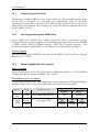
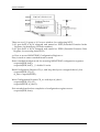
Memory frequency / CPU FSB synchronization
NANO-8045L supports different memory frequencies depending on the CPU front
side bus and the type of DDR2 SO-DIMM.
CPU FSB
533MHz
400 MHz
3.4
Memory Frequency
533/400MHz
400MHz
Installing the Single Board Computer
To install your NANO-8045L into standard chassis or proprietary environment,
please perform the following:
Step 1 : Check all jumpers setting on proper position
Step 2 : Install and configure memory module on right position
Step 3 : Place NANO-8045L into the dedicated position in the system
Step 4 : Attach cables to existing peripheral devices and secure it
WARNING
Please ensure that SBC is properly inserted and fixed by mechanism.
Note:
Please refer to section 3.4.1 to 3.4.4 to install INF/VGA/LAN/Audio drivers.
NANO-8045L User’s Manual
3-2
System Installation
3.4.1
Chipset Component Driver
The chipset on NANO-8045L is a new chipset that a few old operating systems might
not be able to recognize. To overcome this compatibility issue, for Windows
Operating Systems such as Windows XP /VISTA, please install its INF before any of
other Drivers are installed. You can find very easily this chipset component driver in
NANO-8045L CD-title.
3.4.2
Intel Integrated Graphics GMCH Chip
Using Intel® SCH US15W with Media Accelerator High performance graphic
integrated chipset is aimed to gain an outstanding graphic performance. Shared 1MB
to 8MB system DDR2 SO-DIMM Memory with Total Graphics Memory. This
combination makes NANO-8045L an excellent piece of multimedia hardware.
Drivers Support
Please find Springdale GMCH driver in the NANO-8045L CD-title. Drivers support
Windows XP / VISTA.
3.4.3
Realtek Gigabit Ethernet Controller
Drivers Support
Please find Realtek 8111C LAN (J6) drivers in Ethernet directory of NANO-8045L
CD-title. The drivers support Windows XP / VISTA.
LED Indicator (for LAN status)
NANO-8045L provides two LED indicators to report Realtek 8111C Gigabit Ethernet
interface status. Please refer to the table below as a quick reference guide.
8111C
Color
Name of LED
Status
LED
Green
LAN Linked & Active LED
Orange
LAN speed LED
Speed
LED
Green
NANO-8045L User’s Manual
Operation of Ethernet Port
Linked
Active
On
Blinking
Giga
Mbps
100
Mbps
10
Mbps
Orange
Green
Off
3-3
System Installation
3.4.4
Audio Controller
Please find Realtek ALC262 Audio driver form NANO-8045L CD-title. The drivers
support Windows XP / VISTA.
3.5
WDT Function
The algorithm of the WDT function can be simply described as a timer counting
process with an output event. The Time-Out period ( Twd ) can be set by software
commands or hardware jumpers that depend on the board circuit design and may be
different among the boards. This timer can be used to monitor a software hang.
NANO-8045L allows users to control WDT by issuing dynamic software commands.
The WDT starts counting when it is activated. It will cause a system reset once it
expires. Before WDT expires, a refreshing command with a Twd can be issued to
re-count WDT and continue the status monitoring. If the system encounters a
software or application hang , WDT will generate a system reset after its timeout.
The related Control Registers of WDT are included in the following programming
guide that is written in C language. User can write a non-zero value ( defined as Twd )
into the Time-out Value Register ( CR_Twd ) to enable WDT. Users can write 0x00 and
then Twd to CR_Twd to refresh WDT. To refresh WDT, the time tolerance of refreshing
interval must be considered. The smaller of Twd , the more deviation of WDT and you
need to include more tolerance. “Let Twd be longer than 2 seconds” is the
recommendation due to the limitation of Winbond W83627DHG WDT. You can call
Portwell support center for reference. The value read back from CR_Twd indicates the
counting down value instead of the original Twd . System will be reset after the
Time-out Value to be counted down to zero. Users can directly fill a zero value into
CR_Twd to disable WDT immediately. To ensure a successful access to the desired
Control Register, the following programming guide should be followed.
Programming guide :
CR : Configuration Register.
LD : Logical Device of SIO . There are 11 LDs in W83627DHG SIO.
CR00~2F : Global Control Registers. ( All LDs share these CRs )
CR07 : LD selection.
CR30~FF : Each LD has its own CR30~FF.
NANO-8045L User’s Manual
3-4
System Installation
There are two I/O ports as I/O access window for configuring WDT,
1) IO port 0x2E is H/W strapped and named as EFIR (Extended Function Index
Register, for identifying CR index number)
2) IO port 0x2F is H/W strapped and named as EFDR (Extended Function Data
Register, for accessing desired CR)
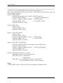
<< How to access W83627DHG Configuration Register >>
First, it needs to enter extended function mode.
Enter extended function mode for accessing W83627DHG configuration registers:
outportb(EFIR, 0x87);
outportb(EFIR, 0x87); // double IO write
Read Configuration Register CR_rx, and keep this byte to unsigned char al_char
outportb(EFIR, CR_rx ) ;
al_char = inportb(EFDR) ;
Write Configuration Register CR_wx with byte al_char1 ;
outportb(EFIR, CR_wx ) ;
outportb(EFDR, al_char1);
Exit extended mode after completion of configuration register access.
outportb(EFIR, 0xaa);
NANO-8045L User’s Manual
3-5
System Installation
***********************************************************************************************
<< How to access W83627DHG WDT Configuration Register >>
Must enter extended function mode first , then follow the following steps for
accessing WDT registers.
Step(1) : CR2B_bit4P0
Initialize the multiplex pin ( pin89 ) to WDTO function
outportb ( EFIR , 0x2B ) ;
// al_char1 : unsigned char
al_char1 = inportb ( EFDR ) & 0xEF ; // CR2B_bit4P0
outportb ( EFIR , 0x2B ) ;
// init pin 89 to WDT
outportb ( EFDR , al_char1 ) ;
Step(2) : CR07_P08
Ponit to LD8.
outportb ( EFIR , 0x07 ) ;
outportb ( EFDR , 0x08 ) ;
Step(3) : LD8_CR30_bit0P1
Activate LD8
outportb ( EFIR , 0x30 ) ;
al_char1 = inportb ( EFDR ) | 0x01 ; // CR30_bit0P1
outportb ( EFIR , 0x30 ) ;
// Activate LD8
outportb ( EFDR , al_char1 ) ;
Step(4) : LD8_CRF7_bit[7,6]P[0,0]
Not allow K/B and Mouse’s interrupts to reload WDT timer.
outportb ( EFIR , 0xF7 ) ;
al_char1 = inportb ( EFDR ) & 0x3F ; // CRF7_bit[7,6]P[0,0]
outportb ( EFIR , 0xF7 ) ;
outportb ( EFDR , al_char1 ) ;
Step(5) : Refresh WDT before it expires.
Once WDT expires , system will be reset.
LD8_CRF5_bit3 : 0 : second unit
1 : minute unit
LD8_CRF6 : Twd , “Writing 00” means “disable WDT”
1~255 time unit( time unit : second, minute )
Notes:
“CR2B_bit4P0“ means ”Write 0 to bit4 of Configuration Register 0x2B”.
NANO-8045L User’s Manual
3-6
System Installation
3.6
GPIO Function
J22 : General Purpose Input/Output Interface Connector
There are 8 GPIO pins on Nano-8045L. GP10, GP11, GP12 and GP13 are dedicated
GPO pins with 12mA current sink capacity at 5V signal level. The output signals
have internal weak pull-high resistor, 4.7K Ohm, to 5V.The GPO signals are
driven by W83627DHG GP30 ~ 33 pins.
GP14, GP15, GP16 and GP17 are dedicated GPI pins. They are first inverted and
then connected to W83627DHG GP34~37 pins.
Refer to the W83627DHG data sheet to configure both input / output port ,
SGP30~37, by programming W83627DHG GPIO registers. Users can configure each
individual port to be an input or output port by programming respective bit in
selection register (0 =output, 1 = input). Invert port value by setting inversion register
(0 = non -inverse, 1 = inverse). Port value is read / written through data register.
In addition, only GP30, GP31 and GP35 are designed to be able to assert PSOUT# or
PME# signal to wake up the system if any of them has any transitions. There are
about 16mS debounced circuit inside these 3 GPIOs and it can be disabled by
programming respective bit (LD9, CR[FEh] bit 4~6).
NANO-8045L User’s Manual
3-7
System Installation
3.6.1
Pin assignment
J16 : General Purpose I/O Connector
PIN No.
1
2
3
4
5
6
7
8
9
10
Signal Description
General Purpose Input Port 10
General Purpose Output Port 14
General Purpose Input Port 11
General Purpose Output Port 15
General Purpose Input Port 12
General Purpose Output Port 16
General Purpose Input Port 13
General Purpose Output Port 17
Ground
+5V
Programming Guide :
Must enter extended function mode ( Double I/O write 0x87 to EFIR ) first , then
follow the following steps for accessing GPIO pins . When completion of GPIO
access, Exit extended mode ( I/O write 0xaa to EFIR ).
void enter_Superio_CFG(void)
{
outportb(Superio_Addr, 0x87);
outportb(Superio_Addr, 0x87);
}
void exit_Superio_CFG(void)
{
outportb(Superio_Addr, 0xAA);
}
(1) Initialize W83627DHG multiplex pins to SGP32~34 function
enter_Superio_CFG();
d = GET_CFG(0x2A);
d = d & 0xFD;
Set_CFG(0x2A, d);
d = GET_CFG(0x2C);
d = d & 0x1F;
Set_CFG(0x2C, d);
NANO-8045L User’s Manual
// Pin 89,90 function selected by CR2C
// Declare Pin88,89,90 as GPIO function
3-8
System Installation
(2) Point to LD9 ( for SGP30~37 GPIO port registers ) and activate its function
Set_CFG(0x07, 0x09);
d = GET_CFG(0x30);
d = d | 0x02;
Set_CFG(0x30, d);
Set_CFG(0xFE, 0x77);
Set_CFG(0xF2, 0x00);
(3) LD9_CRF0_PF0
Set_CFG(0xF0, 0xF0);
// Select logic device 09
//Enable GPIO3
//Declare GP30,GP31,GP35's triggle type is level
and //disable input de-bouncer
//Declare GP30~37 without data inversion
; Set SGP30~33 as GPO pins and SGP34~37 as GPI pin.
//GP30~33 as output;GP34~GP37 as input
(4) LD9_CRF1 ; Data Register for reading/writing data to GPIO pins
; E.g. if put four jumper caps on J16 pin1-2,3-4,5-6,and 7-8
; ( Warning : J16 pin9-10 is not allowed to be short circuit. )
; and then Write [1,0,1,0] to bit[3:0] , you can get [1,0,1,0] from
; bit[7:4].
Set_CFG(0xF1, 0x0A); //GP30~33 output H,L,H,L
d = GET_CFG(0xF1) & 0xF0;
NANO-8045L User’s Manual
3-9
BIOS Setup Information
Chapter 4
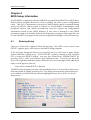
BIOS Setup Information
NANO-8045L is equipped with the AMI BIOS stored in Flash ROM. These BIOS has a
built-in Setup program that allows users to modify the basic system configuration
easily. This type of information is stored in CMOS RAM so that it is retained during
power-off periods. When system is turned on, NANO-8045L communicates with
peripheral devices and checks its hardware resources against the configuration
information stored in the CMOS memory. If any error is detected, or the CMOS
parameters need to be initially defined, the diagnostic program will prompt the user
to enter the SETUP program. Some errors are significant enough to abort the start-up.
4.1
Entering Setup
Turn on or reboot the computer. When the message, “Hit <DEL> if you want to run
SETUP” appears, press <Del> key to enter BIOS setup program.
If the message disappears before you respond, but you still wish to enter Setup,
please restart the system to try “COLD START” again by turning it OFF and then
ON, or touch the "RESET" button. You may also restart from “WARM START” by
pressing <Ctrl>, <Alt>, and <Delete> keys simultaneously. If you do not press the
keys at the right time and the system will not boot, an error message will be displayed
and you will again be asked to,
Press <F1> to Run SETUP or Resume
The BIOS setup program provides a General Help screen. You can call up this screen
from any menu by simply pressing <F1>. The Help screen lists the appropriate keys
to use and the possible selections for the highlighted item. Press <Esc> to exit the
Help screen.
NANO-8045L User’s Manual
4-1
BIOS Setup Information
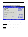
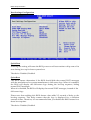
4.2
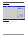
Main Menu
Use this menu for basic system configurations such as time, date etc.
AMI BIOS, Processor, System Memory
These items show the firmware and hardware specifications of your system. Read
only.
System Time
The time format is <Hour> <Minute> <Second>. Use [+] or [-] to configure system
Time.
System Date
The date format is <Day>, <Month> <Date> <Year>. Use [+] or [-] to configure
system Date.
NANO-8045L User’s Manual
4-2
BIOS Setup Information
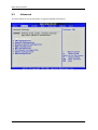
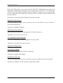
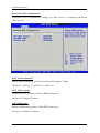
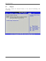
4.3
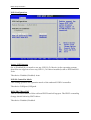
Advanced
Use this menu to set up the items of special enhanced features.
NANO-8045L User’s Manual
4-3
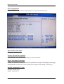
BIOS Setup Information
CPU Configuration
These items show the advanced specifications of your CPU. Read only.
Max CPUID Value Limit
Disable for Windows XP.
Execute-Disable Bit Capability
When disable, force the XD feature flag to always return 0.
Hyper Threading Technology
Enable for Windows XP and Linux4 (OS optimized for Hyper Threading Technology)
and disabled for other OS (OS not optimized for Hyper-Threading Technology)
Intel(R) SpeedSetup(™) tech
Disable: Disable GV3
Enable: Enable GV3
NANO-8045L User’s Manual
4-4
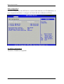
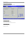
BIOS Setup Information
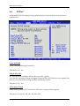
IDE Configuration
The IDE Configuration the IDE devices, such as hard disk drive or CD-ROM drive. It
uses a separate sub menu to configure each hard disk drive (Master and Slave).
ATA/IDE Configuration
The choice: Disabled, Compatible.
NANO-8045L User’s Manual
4-5
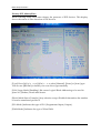
BIOS Setup Information
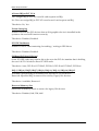
Primary IDE Master/Slave
While entering setup, BIOS auto detects the presence of IDE devices. This display
shows the status of auto detection of IDE devices.
[Type] Press PgUp/<+> or PgDn/<-> to select [Manual], [None] or [Auto] type.
You can use [Manual] to define your own drive type manually.
[LBA/Large Mode] Enabling LBA causes Logical Block Addressing to be used in
place of Cylinders, Heads and Sectors.
[Block (Multi-Sector Transfer)] Any selection except Disabled determines the number
of sectors transferred per block.
[PIO Mode] Indicates the type of PIO (Programmed Input/Output).
[DMA Mode] Indicates the type of Ultra DMA.
NANO-8045L User’s Manual
4-6
BIOS Setup Information
[S.M.A.R.T.] This allows you to activate the S.M.A.R.T. (Self-Monitoring Analysis &
Reporting Technology) capability for the hard disks. S.M.A.R.T is a utility that
monitors your disk status to predict hard disk failure. This gives you an opportunity
to move data from a hard disk that is going to fail to a safe place before the hard disk
becomes offline.
[32 Bit Data Transfer] Enable/Disable 32-bit Data Transfer.
Hard Disk Write Protect
Disabled/Enabled device write protection, this will be effective only if device is
accessed through BIOS.
The choice: Disabled, Enabled.
IDE Detect Time Out (Sec)
Select the time out value for detecting ATA/ATAPI device (s).
The choice: 0, 5, 10, 15, 20, 25, 30, 35.
ATA (PI) 80Pin Cable Detection
Select the mechanism for detecting 80Pin ATA (PI) cable.
The choice: Host & Device, Host, Device.
Super IO Configuration
Serial Port 1 Address
Allows BIOS Select Serial Port1 Base Addresses.
The choice: Disabled, 3F8/IRQ4.
Watch Dog Timer Set
This BIOS testing option is able to reset the system according to the selected table.
The choice: Disabled, 10, 20, 30, 40 Sec, 1Min, 2Min, 4Min.
NANO-8045L User’s Manual
4-7
BIOS Setup Information
Hardware Health Configuration
Configuration / monitor the Hardware Health.
SYSFAN Mode Setting
Fan configuration mode setting.
The choice: Manual Mode, Thermal Cruise Mode.
SYSFAN PWM Control
The PWM duty cycle control.
The choice: 0 to 255.
NANO-8045L User’s Manual
4-8
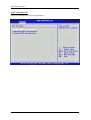
BIOS Setup Information
ACPI Configuration
Select for Advanced ACPI Configuration.
NANO-8045L User’s Manual
4-9
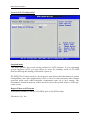
BIOS Setup Information
General ACPI Configuration
Suspend mode
This item specifies the power saving modes for ACPI function. If your operating
system supports ACPI, you can choose to enter the Standby mode in S3 (STR)
function through the setting of this field. Option is:
[S3 (STR)] The S3 sleep mode is a lower power state where the information of system
configuration and open applications/ files is saved to main memory that remains
powered while most other hardware components turn off to save energy. The
information stored in memory will be used to restore the system when a “wake up”
event occurs.
Repost Video on S3 Resume
Determines whether to invoke VGA BIOS post on S3/STR resume.
The choice: No, Yes
NANO-8045L User’s Manual
4-10
BIOS Setup Information
Advanced ACPI Configuration
Advanced ACPI Configuration settings, Use this section to configure additional
ACPI options.
ACPI Version Features
Enable RSDP pointers to 64-bit Fixed System Description Tables.
The choice: ACPI v1.0 / ACPI v2.0 / ACPI v3.0.
ACPI APIC support
Include ACPI APIC table pointer to RSDT pointer list.
The choice: Disabled, Enabled.
AMI OEMB table
Include OEMB table pointer to R(X) SDT pointer list.
The choice: Disabled, Enabled.
NANO-8045L User’s Manual
4-11
BIOS Setup Information
Headless mode
Enable / Disable Headless operation mode through ACPI.
The choice: Disabled, Enabled.
Chipset ACPI Configuration
Chipset ACPI related Configuration settings, Use this section to configure additional
ACPI options.
APIC ACPI SCI IRQ
Enable / Disable APIC ACPI SCI IRQ.
The choice: Disabled, Enabled.
USB Device Wakeup From S3/S4
Enable / Disable USB device Wake from S3/S4 mode.
The choice: Disabled, Enabled.
NANO-8045L User’s Manual
4-12
BIOS Setup Information
MPS Configuration
Configure the Multi-Processor Table.
MPS Revision
This field allows you to select which MPS (Multi-Processor Specification) version to
be used for the operating system. You need to select the MPS version supported by
your operating system. To find out which version to use, consult the vendor of your
operating system.
The choice: 1.1, 1.4.
NANO-8045L User’s Manual
4-13
BIOS Setup Information
PCI Express Configuration
Configure PCI Express Support.
Active State Power-Management
PCI Express L0s and L1 link power states.
The choice: Disabled, Enabled.
NANO-8045L User’s Manual
4-14
BIOS Setup Information
Smbios Configuration
SMBIOS Configuration Menu.
Smbios Smi Support
SMBIOS SMI Wrapper supports for PnP Func 50h-54h.
The choice: Disabled, Enabled.
NANO-8045L User’s Manual
4-15
BIOS Setup Information
USB Configuration
Legacy USB Support
Set to [Enabled] if you need to use any USB 1.1/2.0 device in the operating system
that does not support or have any USB 1.1/2.0 driver installed, such as DOS and SCO
Unix.
The choice: Disabled, Enabled, Auto.
USB 2.0 Controller Mode
This setting specifies the operation mode of the onboard USB 2.0 controller.
The choice: FullSpeed, HiSpeed.
BIOS EHCI Hand-Off
This is a workaround for OSes without EHCI hand-off support. The EHCI ownership
change should claim by EHCI driver.
The choice: Disabled, Enabled.
NANO-8045L User’s Manual
4-16
BIOS Setup Information
4.4
PCIPnP
Advanced PCI/PnP setting wrong values in below sections may cause system to
malfunction.
Clear NVRAM
Clear NVRAM during System Boot.
The choice: No, Yes.
Plug & Play O/S
No: lets the BIOS configure all the devices in the system.
Yes: lets the operating system configure Plug and Play (PnP) devices not required for
boot if your system has a Plug and Play operating system.
The choice: No, Yes.
PCI Latency Timer
Select value in units of PCI clocks for PCI device latency timer register.
The choice: 32, 64, 96, 128, 160, 192, 224, 248.
NANO-8045L User’s Manual
4-17
BIOS Setup Information
Allocate IRQ to PCI VGA
Yes: Assigns IRQ to PCI VGA card if card requests an IRQ.
No: Does not assign IRQ to PCI VGA card even if card requests an IRQ.
The choice: No, Yes.
Palette Snooping
Enabled: informs the PCI devices that an ISA graphics device is installed in the
system so the card will function correctly.
The choice: Disabled, Enabled.
PCI IDE BusMaster
Enabled: Uses PCI bus mastering for reading / writing to IDE drives.
The choice: Disabled, Enabled.
OffBoard PCI/ISA IDE Card
Some PCI IDE cards may require this to be set to the PCI slot number that is holding
the card. AUTO: Works for most PCI IDE cards.
The choice: Auto, PCI Slot1, PCI Slot2, PCI Slot3, PCI Slot4, PCI Slot5, PCI Slot6.
IRQ 3 / IRQ 4 / IRQ5 / IRQ7 / IRQ 9 / IRQ 10 / IRQ 11 / IRQ 14 / IRQ 15
Available: Specified IRQ is available to be used by PCI/PnP devices.
Reserved: Specified IRQ is reserved for used by Legacy ISA devices.
The choice: Available, Reserved.
Reserved Memory Size
Select Size of memory block to reserve for legacy ISA devices.
The choice: Disabled, 16K, 32K, 64K.
NANO-8045L User’s Manual
4-18
BIOS Setup Information
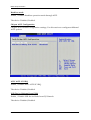
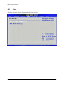
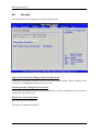
4.5
Boot
Use this menu to specify the priority of boot devices.
NANO-8045L User’s Manual
4-19
BIOS Setup Information
Boot Settings Configuration
Quick Boot
Enabling this setting will cause the BIOS power-on self test routine to skip some of its
tests during boot up for faster system boot.
The choice: Disabled, Enabled.
Quiet Boot
This BIOS feature determines if the BIOS should hide the normal POST messages
with the motherboard or system manufacturer's full-screen logo. When it is enabled,
the BIOS will display the full-screen logo during the boot-up sequence, hiding
normal POST messages.
When it is disabled, the BIOS will display the normal POST messages, instead of the
full-screen logo.
Please note that enabling this BIOS feature often adds 2-3 seconds of delay to the
booting sequence. This delay ensures that the logo is displayed for a sufficient
amount of time. Therefore, it is recommended that you disable this BIOS feature for a
faster boot-up time.
The choice: Disabled, Enabled.
NANO-8045L User’s Manual
4-20
BIOS Setup Information
AddOn ROM Display Mode
This item is used to determine the display mode when an optional ROM is initialized
during POST. When set to [Force BIOS], the display mode used by AMI BIOS is used.
Select [Keep Current] if you want to use the display mode of optional ROM.
The choice: Force BIOS, Keep Current.
Bootup Num-Lock
This setting is to set the Num Lock status when the system is powered on.
Setting to [On] will turn on the Num Lock key when the system is powered on.
Setting to [Off] will allow users to use the arrow keys on the numeric keypad.
The choice: Off, On.
PS/2 Mouse support
Select [Enabled] if you need to use a PS/2-interfaced mouse in the operating system.
The choice: Disabled, Enabled, Auto.
Wait For ‘F1’ If Error
When this setting is set to [Enabled] and the boot sequence encounters an error, it
asks you to press F1. If disabled, the system continues to boot without waiting for you
to press any keys.
The choice: Disabled, Enabled.
Hit ‘DEL’ Message Display
Set this option to [Disabled] to prevent the message as follows:
Hit Del if you want to run setup
It will prevent the message from appearing on the first BIOS screen when the
computer boots. Set it to [Enabled] when you want to run the BIOS Setup Utility.
The choice: Disabled, Enabled.
Interrupt 19 Capture
Interrupt 19 is the software interrupt that handles the boot disk function. When
enabled, this BIOS feature allows the ROM BIOS of these host adaptors to "capture"
Interrupt 19 during the boot process so that drives attached to these adaptors can
function as bootable disks. In addition, it allows you to gain access to the host
adaptor's ROM setup utility, if one is available.
NANO-8045L User’s Manual
4-21
BIOS Setup Information
When disabled, the ROM BIOS of these host adaptors will not be able to "capture"
Interrupt 19. Therefore, you will not be able to boot operating systems from any
bootable disks attached to these host adaptors. Nor will you be able to gain access to
their ROM setup utilities.
The choice: Disabled, Enabled.
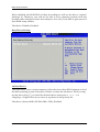
Boot Device Priority
1st Boot Device
The items allow you to set the sequence of boot devices where BIOS attempts to load
the disk operating system. First press <Enter> to enter the sub-menu. Then you may
use the arrow keys (↑↓) to select the desired device, then press <+>, <-> or
<PageUp>, <PageDown> key to move it up/down in the priority list.
The choice: (Network:IBA GE Slot 0200 v1324), Disabled.
NANO-8045L User’s Manual
4-22
BIOS Setup Information
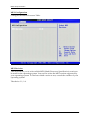
4.6
Security
Use this menu to set supervisor and user passwords.
Supervisor Password / Change Supervisor Password
Supervisor Password controls access to the BIOS Setup utility. These settings allow
you to set or change the supervisor password.
User Password / Change User Password
User Password controls access to the system at boot. These settings allow you to set or
change the user password.
Boot Sector Virus Protection
Boot Sector Virus Protection.
The choice: Disabled, Enabled.
NANO-8045L User’s Manual
4-23
BIOS Setup Information
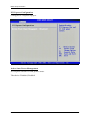
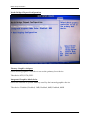
4.7
Chipset
This menu controls the advanced features of the onboard Northbridge and
Southbridge.
NANO-8045L User’s Manual
4-24
BIOS Setup Information
North Bridge Chipset Configuration
Primary Graphics Adapter
Select which graphics controller to use as the primary boot device.
The choice: IGD, PCIe/IGD.
Integrated Graphics Mode Selec
Select the amount of system memory used by the internal graphics device.
The choice: Disabled, Enabled, 1MB, Enabled, 4MB, Enabled, 8MB.
NANO-8045L User’s Manual
4-25
BIOS Setup Information
Boot Display Configuration
Boot Display Device
The choice: Auto, Integrated LVDS, External DVI/HDMI, External TV, External CRT
External LVDS.
Local Flat Panel Scaling
The choice: Auto, Forced Scaling, Disabled.
Flat Panel Type
The choice: 640x480 (generic), 800x600 (generic), 1024x768 (generic), 640x480 (NEC
8.4”), 800x600 (NEC 9”), 1024x600 (TMD 5.61”), 1024x600 (Samsung
4.8”), 1024x768 (Samsung 15”), 1280x768 (Sharp 7.2”), 1280x800
(Samsung 15.4”), 1366x768 (TMD 11.1").
DPST Control
The choice: VBIOS-Default, DPST Disabled, DPST Enabled at Level 1~Level 5.
TV Standard
The choice: VBIOS-Default, NTSC, PAL, SECAM, SMPTE240M, ITU-R television,
SMPTE295M, SMPTE296M, CEA 7702, CEA 7703.
NANO-8045L User’s Manual
4-26
BIOS Setup Information
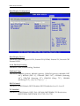
South Bridge Chipset Configuration
USB Functions
This setting specifies the function of the onboard USB controller.
The choice: Disabled, 2 USB Ports, 4 USB Ports, 6 USB Ports.
USB 2.0 Controller
Set to [Enabled] if you need to use any USB 2.0 device in the operating system that
does not support or have any USB 2.0 driver installed, such as DOS.
The choice: Enabled, Disabled.
USB Client Controller
The choice: Enabled, Disabled.
SDIO controller
The choice: Enabled, Disabled.
Audio Controller Codec
The choice: Auto, Azalia, Disabled.
NANO-8045L User’s Manual
4-27
BIOS Setup Information
SLP_S4# Min. Assertion Width
The choice: 4 to 5 seconds, 3 to 4 seconds, 2 to 3 seconds, 1 to 2 seconds.
Restore on AC Power Loss
This item allows user to configure the power status of using ATX power supply after
a serious power loss occurs.
The choice: Power Off, Power On, Last State.
Serial IRQ Mode
The choice: Continuous, Quiet.
PCIE Port 0
The choice: Auto, Enabled, Disabled.
PCIE Port 1
The choice: Auto, Enabled, Disabled.
NANO-8045L User’s Manual
4-28
BIOS Setup Information
4.8
Exit
This menu allows you to load the BIOS default values or factory default settings into
the BIOS and exit the BIOS setup utility with or without changes.
Save Changes and Exit
Exit System Setup and save your changes to CMOS. Pressing <Enter> on this item
asks for confirmation: Save changes to CMOS and exit the Setup Utility.
Discard Changes and Exit
Abandon all changes and exit the Setup Utility.
Discard Changes
Abandon all changes and continue with the Setup Utility.
Load Optimal Defaults
Use this menu to load the default values set by the SBC manufacturer specifically for
optimal performance of the SBC.
NANO-8045L User’s Manual
4-29
BIOS Setup Information
Load Failsafe Defaults
Use this menu to load the default values set by the BIOS vendor for stable system
performance.
NANO-8045L User’s Manual
4-30
Troubleshooting
Chapter 5
Troubleshooting
This chapter provides a few useful tips to quickly get NANO-8045L running with
success. As basic hardware installation has been addressed in Chapter 2, this chapter
will primarily focus on system integration issues, in terms of BIOS setting, and OS
diagnostics.
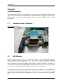
5.1
Hardware Quick Installation
DC 12V Power Input
5.2
BIOS Setting
It is assumed that users have correctly adopted modules and connected all the device
cables required before turning on DC 12V power. 200-pin DDR2 SO-DIMM,
keyboard, mouse, SATA hard disk, VGA connector, device power cables, 12V DC
power accessories are good examples that deserve attention. With no assurance of
properly and correctly accommodating these modules and devices, it is very possible
to encounter system failures that result in malfunction of any device.
To make sure that you have a successful start with NANO-8045L, it is recommended,
when going with the boot-up sequence, to hit “DEL” key and enter the BIOS setup
menu to tune up a stable BIOS configuration so that you can wake up your system far
well.
NANO-8045L User’s Manual
5-1
Troubleshooting
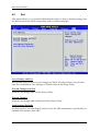
Loading the default optimal setting
When prompted with the main setup menu, please scroll down to “Load Optimal
Defaults”, press “Enter” and chose “OK” to load in default optimal BIOS setup. This
will force your BIOS setting back to the initial factory configuration. It is
recommended to do this so you can be sure the system is running with the BIOS
setting that Portwell has highly endorsed. As a matter of fact, users can load the
default BIOS setting any time when system appears to be unstable in boot up
sequence.
Improper disable operation
There are too many occasions where users disable a certain device/feature in one
application through BIOS setting. These variables may not be set back to the original
values when needed. These devices/features will certainly fail to be detected.
When the above conditions happen, it is strongly recommended to check the BIOS
settings. Make sure certain items are set as they should be. These include the COM1
port, USB ports, external cache, on-board VGA and Ethernet.
It is also very common that users would like to disable a certain device/port to
release IRQ resource. A few good examples are
Disable COM1 serial port to release IRQ #4
Etc…
A quick review of the basic IRQ mapping is given below for your reference.
IRQ#
IRQ #0
IRQ #1
IRQ #2
IRQ #3
IRQ #4
IRQ #5
IRQ #6
IRQ #7
IRQ #8
IRQ #9
IRQ #10
IRQ #11
IRQ #12
IRQ #13
IRQ #14
IRQ #15
Description
System Counter
Keyboard
Programmed Controller
COM2
COM1
Sound, Network, USB 1.0/1.1 UHCI Controller
Floppy Disk Controller
Printer Port (Parallel Port)
CMOS / Real Time Clock
ACPI Controller
SCSI adapter, Video card, USB controller
Network Controller
PS/2 Mouse Connector
Math coprocessor
Primary IDE Controller
Secondary IDE Controller
NANO-8045L User’s Manual
5-2
Troubleshooting
It is then very easy to find out which IRQ resource is ready for additional peripherals.
If IRQ resource is not enough, please disable some devices listed above to release
further IRQ numbers.
5.3
FAQ
Installation Problem
Question: How do I connect my keyboard and mouse if the NANO-8045L do not
have PS/2 connector?
Answer: You may use USB keyboard and mouse to connect on USB interface.
Information & Support
Question: How can I connect my NANO-8045L series to panel?
Answer: First of all, you need to read the Panel spec and Inverter spec to understand
which type of panel you will use on NANO-8045L series; different panel
will connect to different connector; LVDS interface is J14.
Question: How can I change COM port to RS-232/RS-422/RS-485 mode?
Answer: NANO-8045L only supports RS-232 as default. There is no RS-422/RS-485
for NANO-8045L.
Note:
Please visit our technical web site at
http://www.portwell.com.tw
For additional technical information, which is not covered in this manual, you can
mail to [email protected] or you can also send mail to our sales, they will be
very delighted to forward them to us.
NANO-8045L User’s Manual
5-3
Appendix A
System Memory Address Map
Each On-board device in the system is assigned a set of memory addresses, which
also can be identical of the device. The following table lists the system memory
address used for your reference.
Memory Area
0000-003F
0040-004F
0050-006F
0070-040A
040B-04C6
04C7-9FBF
9FC0-9FFF
A000-AFFF
B000-B7FF
B800-BFFF
C000-CE5F
CE60- EFFF
F000-FFFF
NANO-8045 User’s Manual
Size
1K
0.3K
0.5K
Device Description
Interrupt Area
BIOS Data Area
System Data
14K
DOS
2.9K
Program Area
619K
[Available]
= Conventional memory ends at 639K =
1K
Extended BIOS Area
64K
VGA Graphics
32K
Unused
32K
VGA Text
57K
Video ROM
134K
Unused
64K
System ROM
Appendix B
Interrupt Request Lines (IRQ)
Peripheral devices can use interrupt request lines to notify CPU for the service
required. The following table shows the IRQ used by the devices on board.
IRQ#
IRQ 0
IRQ 1
IRQ 2
IRQ 3
IRQ 4
IRQ 5
IRQ 6
IRQ 7
IRQ 8
IRQ 9
IRQ 10
IRQ 11
IRQ 12
IRQ 13
IRQ 14
IRQ 15
Current Use
System ROM
System ROM
[Unassigned]
[Unassigned]
System ROM
[Unassigned]
System ROM
Unused
System ROM
[Unassigned]
[Unassigned]
[Unassigned]
System ROM
System ROM
System ROM
[Unassigned]
NANO-8045 User’s Manual
Default Use
System Timer
Keyboard Event
Usable IRQ
Usable IRQ
COM1
Usable IRQ
Diskette Event
Usable IRQ
Real-Time Clock
Usable IRQ
Usable IRQ
Usable IRQ
IBM Mouse Event
Coprocessor Error
Hard Disk Event
Usable IRQ