1
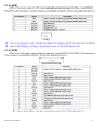
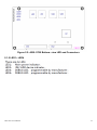
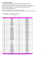
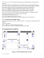
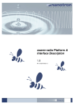
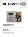
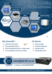
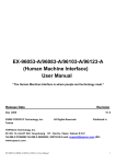
APC-3081 IP65 Rugged Panel PC User Manual Release Date Revision Feb. 2012 V1.0 ®2011 Aplex Technology, Inc. All Rights Reserved. Published in Taiwan Aplex Technology, Inc. 15F-1, No.186, Jian Yi Road, Zhonghe District, New Taipei City 235, Taiwan Tel: 886-2-82262881 APC-3081 User Manual Fax: 886-2-82262883 E-mail: [email protected] URL: www.aplex.com.tw 1 Warning!____________________________________ This equipment generates, uses and can radiate radio frequency energy and if not installed and used in accordance with the instructions manual, it may cause interference to radio communications. It has been tested and found to comply with the limits for a Class A computing device pursuant to FCC Rules, which are designed to provide reasonable protection against such interference when operated in a commercial environment. Operation of this equipment in a residential area is likely to cause interference in which case the user at his own expense will be required to take whatever measures may be required to correct the interference. Electric Shock Hazard – Do not operate the machine with its back cover removed. There are dangerous high voltages inside. Disclaimer This information in this document is subject to change without notice. In no event shall Aplex Technology Inc. be liable for damages of any kind, whether incidental or consequential, arising from either the use or misuse of information in this document or in any related materials. APC-3081 User Manual 2 Table of Contents______________________ Warning!…………………………………………………………………………….……..….2 Disclaimer………………………………………………………………….…………………2 Chapter 1 Getting Started 1.1 Features…....………………….………………………….…………..…...…4 1.2 Specifications………………………………………….………….……...…..4 1.3 Dimensions…………………………………...……………….…………......6 1.4 Brief Description……………………………………….…………………7 1.5 Installation of Brackets.....................................................8 Chapter 2 Hardware Installation 2.1 Mainboard.....…...………………………………….………………………10 2.2 Component Locations...…...………………………………….……………19 Chapter 3 Installations of BIOS 3.1 System Test and Initialization……………………………….……………28 3.2 Award BIOS Setup………………………………………………………….28 Chapter 4 Installations of Drivers 4.1 Intel Chipset Software Installation…………………….….….……………31 4.2 VGA Driver installation..........................................................................35 4.3 Intel PRO LAN Drivers installation.........................................................38 4.4 Realtek Audio Driver installation............................................................41 Chapter 5 Touch Screen Installation 5.1 Introduction to Touch Screen Controller Board......................................43 5.2 Windows 2000/XP/2003/Vista Universal Driver Installation…………..43 Figures Figure 1.1: Dimensions ………………………………………………………...6 Figure 1.2: Front View of APC-3081…………………….……………………...7 Figure 1.3: Rear View of APC-3081……………………..……………………...7 Figure 2.1: ASB- S700 Top-view connectors……………..………..…………10 Figure 2.2: ASB- S700 Bottom-view LED and Connectors…………………12 Figure 2.3: PB-703 Baseboard Overview…………………………………….19 Figure 2.4: PB-703 R1.10 Board overview………………………………...…25 Figure 5.1: Bird’s Eye View of Control Board..............................................43 APC-3081 User Manual 3 Chapter 1_____________________________ 1.1 Features 8” LED backlight TFT LCD with resolution of 800x600, 400 cd/m2 Rugged Panel PC / Fan-less Design / totally IP-65 rating Intel ATOM Z510 1.1G, Optional Z530 1.6GHz Processor 1GB DDR2 SDRAM on board 9-32V DC power input 5-wire resistive touch screen 1.2 Specifications Model No. AHM-6086A Specs System Processor Intel Atom Z510 1.1GHz processor, optional Z530 1.6GHz processor System Chipset Intel US15W System Memory 1GB DDR2 400 MHz SDRAM on board Storage 1 x 2 .5" SATA HDD or SSD Space 1 x CF Slot (on board) External I/O Port 1 x DC power input 1 x Gigabit LAN 1 x COM1 RS-232 2 x USB ports Expansion Slots None OS support Windows CE 5.0, Windows XP, XP Embedded LCD Display Type 8” TFT-LCD Max. Resolution 800x600 Max. Color 262K Luminance (cd/m2) 350, 800nits for option View Angle H:140° / V:100° Backlight Lifetime 40,000 hrs Touch Screen Type APC-3081 User Manual Resistive Touch (Optional) 4 Light Transmission 80% Power Supply Power Input DC 9~32V Mechanical Construction Aluminum die casting housing IP Rating IP65 Mounting VESA 75x75 Mount Dimensions (WxHxD) 251 (W) x 201 (H) x 63 (D) mm Environmental Operating Temperature 0~50 ゚ C / -20~70 ゚ C (Wide temperature model) Storage Temperature -20~60 ゚ C / -30~85 ゚ C (Wide temperature model) Storage Humidity 10~90% @40 ゚ C non-condensing Certificate Meet CE/FCC Class A APC-3081 User Manual 5 1.3 Dimensions Figure 1.1: Dimensions of the APC-3081 APC-3081 User Manual 6 1.4 Brief Description of the APC-3081 The APC-3081 is a Fanless IP65 Waterproof Solution rugged Panel PC, powered by Intel Atom Z510 1.1GHz, and supporting 2 x USB Port, 1 x COM port, 1 x LAN Port, 1 x DC power input and totally IP65 rating connectors. It comes with Wi-Fi, Bluetooth, GPS module for option. It features in the design of full IP65, Anti-vibration and shock resistant. It's an excellent choice for harsh industrial and outdoor Automation. Figure 1.2: Front View of APC-3081 Figure 1.3 Rear View of APC-3081 APC-3081 User Manual 7 1.5 Installation of Brackets Step 1 There are 4 screws to deal with when fixing the base estimated location. Step 2 Get the Side bracket screwed to the model with the four screws as shown by the arrows in the picture. Step 3 Fix the model to the base as shown in the picture, making sure the two screws is rightly positioned. Get the two screws as circled tightened to secure the base. As shown in the picture APC-3081 User Manual 8 Step 4 That’s how it should look after it has been installed. APC-3081 User Manual 9 Chapter 2 Hardware Installation 2.1 Mainboard Figure 2.1: ASB- S700 Top- view connectors 2.1.1 JTAG1 2.1.2 TPM1 APC-3081 User Manual 10 2.1.3 LVDS1 2.1.4 LVDS2 APC-3081 User Manual 11 Figure 2.2: ASB- S700 Bottom- view LED and Connectors 2.1.5 LED1~ LED4 APC-3081 User Manual 12 2.1.6 CN1 pins- assignment APC-3081 User Manual 13 APC-3081 User Manual 14 2.1.6.1 NC- Pin Means non- connected pin, part of the pins of CN1/ CN2 (left or right) are not connected for reservation Purpose 2.1.6.2 RSV- Pin This pin was reserved for specific function and definition maybe different from CN1 or CN3 (top or down) 2.1.6.3 GND ground pin 2.1.6.4 Power Supply Source Class There are four pins for power supply sources on CN1: 12V_S5, is defined for 12V standby power, connected Pin 1, 3, 5, 7, 9, 11 of total six pins, can secure transmission current up to 2.4 Amp. 3P3V_S5, is defined for 3.3V standby power, connected Pin 17, 19, 21, 23 of total four pins, can secure transmission current up to 1.6 Amp. 3P3V_S0, is defined for 3.3V system power source, connected Pin 44, 46, 48, 50, 52, 54 of total six pins, can secure transmission current up to 2.4Amp. 5V_S0, is defined for 5V system power source, connected Pin 22, 24, 26, 28, 29, 31, 33, 35 of total eight pins, can secure transmission current up to 3.2 Amp. 2.1.6.5 IDE bus signal Pin 37 and the odd pin- number in between #41 ~ # 97 are defined for IDE bus signals. 2.1.6.6 PCIE (PCI-Express) bus- signals ASB-S700 supports two PCI-E 1x bus. (1x lanes) Pin 4, 6 are defined for the PCIE1 differential negative as positive input signal, Pin16, 18 are defined for the PCIE1 differential negative as positive output signal, and Pin10, 12 are defined for the differential negative as the clockwise output signal. Pin 58, 60 are defined for the PCIE2 differential positive as negative output signal, Pin88, 90 are defined for the PCIE2 differential positive as negative input signals, Pin82, 84 are defined for the differential positive as counterclockwise output signal 2.1.6.7 SDIO bus signal Pin 68, 70, 72, 74, 78, 94, 96 are for the SDIO bus signals, can support 4 bit SDIO devices. Pin 32, 34, 64, 66 are reserved and malfunction. APC-3081 User Manual 15 2.1.6.8 Other Signals Pin36, US15W's GPIO3 signal (the initial status is defined as the output); Pin38, US15W's GPIOSUS0 signal (the initial status is defined as the input); Pin40, PCIE_PME # signal, the external device wake-up signal (#, said active-low); Pin42, US15W's GPIO8 signal; (can be defined for LAN disable signal) Pin92, US15W the GPIO6 signal; Pin98, SCH_SLP3 # signal, control system power supply; Pin100, SIO_PSON # signal, SIO transferred switching ON/ OFF power supply signal. 2.1.7 CN2 pins- assignment (R1.30) APC-3081 User Manual 16 2.1.7.1 NC- Pin Means non- connected pin, part of the pins of CN1/ CN2 (left or right) are not connected for reservation purpose. RSV- Pin This pin was reserved for specific function and definition maybe different from CN1 or CN3 (top or down) GND ground pin APC-3081 User Manual 17 2.1.7.2 Power Supply Pin CN2, CN4 defined two kinds of power supply sources. VCC_RTC, is defined for the Real-Time-Clock power supply, ASB-S700 is equipped with a lithium battery (CR2032) also the onboard battery is also for the baseboard used. 5V_S5, is defined for 5V Standby power source, connected Pin63, 65, 67, 69, 71, 73 of total of six pins, can secure transmission current up to 2.4 Amp. 2.1.7.3 LPC Bus Signal Pin36, 48 and odd-number of pin 19 ~ 29 are defined for LPC Bus signals. 2.1.7.4 USB Bus Signal Pin77, 79, Pin56, 58, Pin62, 64, Pin68, 70, Pin74, 76, Pin80, 82, are defined set of differential pairs of negative as positive signals of USB. Pin83, 85, 87 are defined as over-current protection signal for relevant USB ports. 2.1.7.5 SMB Bus Signal Pin2, 4 are defined for the SMB Bus signals 2.1.7.6 SDVO Bus Signal The even-number of Pin8 ~ 52 are defined for SDVO Bus signals 2.1.7.7 HDA Bus Signal The even-number of Pin84 ~ 94 are defined for High Definition Audio Bus signals of Intel. 2.1.7.8 Clock Signals Pin7 is defined for 32.768 KHz clock signal, output from CPU board, core-module of mini-Express. Pin37 is defined for the 33MHz clock signal, output from CPU board, core-module of mini-Express. Pin41 is defined for the 48MHz clock signal, output from CPU board, core-module of mini-Express. 2.1.7.9 Other Signals Pin3, A20GATE, is defined for A20 GATE signal as issued by SIO. (Serial Input/ Output) Pin5, KB_RST #, is defined for Keyboard Reset as issued by SIO. (#, said active-low); Pin9, FP_RST #, is defined as forced Reset signal from external input; Pin11, RST_OUT1 #, CPU board, core-module send-out reset signal #1 to the adapted IO baseboard. Pin13, RST_OUT2 #, CPU board, core-module send-out reset signal #2 to the adapted IO baseboard. Pin15, IO_THRM #, IO baseboard send the system thermal- overheat signal to CPU board. Pin31, RSM_RST #, IO baseboard send system reboot ready signal to CPU board.; Pin33, CPU_CORE_SENSE, CPU core- power supply voltage detection; Pin42, multiplexed signal can be used for LPC_PME # and GPIO; Pin45, EN_3V_5V_S0 #, CPU board send the main power system signal to IO baseboard for operating APC-3081 User Manual 18 Pin47, EN_3V_5V_S5, CPU board send an auxiliary power supply signal to IO baseboard for operating. Pin49, SMC_ONOFF #, IO baseboard send to CPU board to issue a system ON/ OFF signal; Pin51, 3V_5V_S5_OK, IO baseboard issued confirmed auxiliary power OK signal to CPU board; Pin53, SMC_LATCH #, CPU board sent disable system signal to the IO baseboard; Pin57, CPU_THERMDA, Defined the thermal diode positive signal to CPU board; Pin59, CPU_THERMDC, Defined the thermal diode negative signal to CPU board; Pin89, SIO_PWROK, IO baseboard send to the power OK signal to CPU board; Pin91, USB2_CLIENT_EN, USB2_CLIENT signal enable, but also can be defined as GPIO; Pin93, from the US15W access via CPLD out as defined GPIO; Pin95, Software Reset signal, active low; Pin97, AT Power Mode allows signal, active low; Pin100, SCH_SPKR, CPU board sent to the buzzer signal- sound to IO baseboard 2.1.7.10 LVDS panel backlight signal The main different functions of Rev: 1.20 version and Rev: 1.30 version is the CN2 added LVDS backlight control screen signals. Pin 96 L_BKLEN, is defined for Backlight start signal; Pin 98 L_BKLCTRL, is defined for backlight brightness control signal. 2.2 Component Locations Figure 2.3: PB-703 Baseboard Overview APC-3081 User Manual 19 2.2.1 PWR1/PWR2 The power input of PCB was co-designed with PWR1or PWR2 for pre-selection。 PWR1 will use CJT brand like A3963WV-2P type connectors,PWR2 may use DINKLE brand like DT-126RP-02P type connectors。PWR1/PWR2 are different housing design but same pin defined: 2.2.2 USB4/5 2.2.3 JP3 JP3 is designed for auto-on switch jumper with 2xPin-header as pitch 2.0mm type. JP3 defaulted with closed jumper, system will be on when DC power input. If JP3is open jumper, system power-on will be controlled by firmware of ASB-S700. 2.2.4 BAT1 APC-3081 User Manual 20 2.2.5 MPCIE1 [ mini- PCI express ] Mini PCI Express slot for full-/ half- size add-in card,initial designed for full-size mPCIe could be fixed on A1 and B1,optional designed for half-size mPCIe could be fixed on C1 and D1 2.2.6 JP1 2.2.7 JP4 2.2.8 IDE_CF1 APC-3081 User Manual 21 2.2.9 INVERTER 2.2.10 JP2 2.2.11 SATA 2.2.12 SATA_P1 APC-3081 User Manual 22 2.2.13 JP5 2.2.14 J1 Port APC-3081 User Manual 23 2.2.15 J2 port APC-3081 User Manual 24 Figure 2.4: PB-703 R1.10 Board overview APC-3081 User Manual 25 2.2.16 CN3 APC-3081 User Manual 26 2.2.17 CN4 2.2.18 PB-703 assembly PCB dimension:115mm × 70mm ×1.6mm Main assembly holes like A,B,C,D of PB-703 may adapt to A、B、C、Dholes of ASB-S700 (SOM) and baseboard (PB-703) could be fixed by 4x 6mm +/- 0.1mm height nuts Mini-PCI express card could be fixed by A1,B1,C1,D1:default A1,B1 for full-size mPCIe add-on card and C1,D1 for half-size mPCIe add-on card. APC-3081 User Manual 27 Chapter 3 BIOS Setup 3.1 System Test and Initialization These routines test and initialize board hardware. If the routines encounter an error during the tests, you will either hear a few short beeps or see an error message on the screen. There are two kinds of errors: fatal and non-fatal. The system can usually continue the boot up sequence with non-fatal errors. Non-fatal error messages usually appear on the screen along with the following instructions: Press <F1> to RESUME Write down the message and press the F1 key to continue the boot up sequence. System configuration verification These routines check the current system configuration against the values stored in the CMOS memory. If they do not match, the program outputs an error message. You will then need to run the BIOS setup program to set the configuration information in memory. There are three situations in which you will need to change the CMOS settings: 1. You are starting your system for the first time 2. You have changed the hardware attached to your system 3. The CMOS memory has lost power and the configuration information has been erased. 3.2 Award BIOS Setup Awards BIOS ROM has a built-in Setup program that allows users to modify the basic system configuration. This type of information is stored in battery-backed CMOS RAM so that it retains the Setup information when the power is turned off. Entering Setup Power on the computer and press <Del> immediately. This will allow you to enter Setup. Standard CMOS Features Use this menu for basic system configuration. (Date, time, IDE, etc.) Advanced BIOS Features Use this menu to set the advanced features available on your system. Advanced Chipset Features Use this menu to change the values in the chipset registers and optimize your system performance. Integrated Peripherals APC-3081 User Manual 28 Use this menu to specify your settings for integrated peripherals. (Primary slave, secondary slave, keyboard, mouse etc.) Power Management Setup Use this menu to specify your settings for power management. (HDD power down, power on by ring, KB wake up, etc.) PnP/PCI Configurations This entry appears if your system supports PnP/PCI. PC Health Status This menu allows you to set the shutdown temperature for your system. Frequency/Voltage Control Use this menu to specify your settings for auto detect DIMM/PCI clock and spread spectrum. Load Fail-Safe Defaults Use this menu to load the BIOS default values for the minimal/stable performance for your system to operate. Load Optimized Defaults Use this menu to load the BIOS default values that are factory settings for optimal performance system operations. While AWARD has designated the custom BIOS to maximize performance, the factory has the right to change these defaults to meet their needs. Set Supervisor/User Password Use this menu to set Supervisor/User Passwords. Save and Exit Setup Save CMOS value changes to CMOS and exit setup. Exit Without Saving Abandon all CMOS value changes and exit setup. APC-3081 User Manual 29 Chapter 4 Installation of Drivers This chapter describes the installation procedures for software and drivers under the windows XP. The software and drivers are included with the motherboard. The contents include Intel chipset driver, VGA driver, LAN driver, Audio driver Installation instructions are given below. Important Note: After installing your Windows operating system (Windows 98SE/ME/2000/XP), you must install first the Intel Chipset Software Installation Utility before proceeding with the installation of drivers. APC-3081 User Manual 30 4.1 Intel Chipset Software Installation The Intel Chipset Drivers should be installed first before the software drivers to enable Plug & Play INF support for Intel chipset components. Follow the instructions below to complete the installation Under Windows XP 1. Insert the Aplex product CD that comes with the board. 2. Click “ Intel® Chipset software installation Utility “ APC-3081 User Manual 31 3. When the Welcome screen appears, please click “ Next “ to Continue. 4. Click Yes to accept the software license agreement and proceed with the installation process. APC-3081 User Manual 32 5. On Readme Information screen, click Next to continue the installation. APC-3081 User Manual 33 6. The Setup process is now complete. Click Finish to restart the computer and for changes to take effect. APC-3081 User Manual 34 4.2 VGA Driver installation To install the VGA Driver follow the steps below to proceed with the installation. Step 1. Insert the Aplex product CD That comes with the board. Step 2. Click “ Intel® VGA Chipset “ Step 3. When the Welcome screen appears , click “Next” to continue. APC-3081 User Manual 35 Step 4. Click YES to agree with the license agreement and continue the installation. APC-3081 User Manual 36 Step 5. The Setup process is now complete. Click Finish to restart the computer as promoted and for changes to take effect. When the computer has restarted, the system will be able to find some devices. Restart your computer when prompted. APC-3081 User Manual 37 4.3 Intel PRO LAN Drivers installation Follow the steps below to complete the installation of the Intel PRO LAN drivers. Step 1. Insert the Aplex product CD That comes with the board. Step 2. Click “Intel® Ethernet Driver“ Step 3. When the Welcome screen appears , click “Next” to continue. APC-3081 User Manual 38 APC-3081 User Manual 39 Step 4. Click “Finish” to restart the computer and for changes to take effect APC-3081 User Manual 40 4.4 Realtek Audio Driver installation To install the Realtek codec Driver follow the steps below to proceed with the installation. Step 1. Insert the Aplex product CD That comes with the board. Step 2. Click “Realtek ‘ Codec Sound system “ Step 3. When the Welcome screen appears, click “Next” to continue. APC-3081 User Manual 41 Step 4. Click “Finish” to restart the computer and for changes to take effect. APC-3081 User Manual 42 Chapter 5 Touch Screen Installation This chapter describes how to install drivers and other software that will allow your PenMount 6000 Controller Board to work with different operating systems. NOTE: PenMount USB drivers support up to 15 USB controllers. 5.1 Introduction to Touch Screen Controller Board PenMount 6300 USB control board is a touch screen control board designed for USB interface and specific for 4, 5, 8-wire touch screens. It is designed with USB interface features with multiple devices supporting function. PenMount 6300 control board using PenMount 6000 controller that has been designed for those who may like and all-in-one solution with 10-bit A/D converter built-in to make the total printed circuit board denser, circuit diagram also designed for 12-bit ADC for optional. There are two connectors on this board, one connector is for 4, 5, 8-wire touch screen cable (optional), and another is for 4-pin USB A type cable (optional). Figure 5.1: Bird’s Eye View of Control Board 5.2 Windows 2000/XP/2003/Vista Universal Driver Installation for PenMount 6000 Series Before installing the Windows 2000/XP driver software, you must have the Windows 2000/XP system installed and running on your computer. You must also have one of the following PenMount 6000 series controller or control boards installed: PM6500, PM6300. APC-3081 User Manual 43 5.2.1 Installing Software If you have an older version of the PenMount Windows 2000/XP driver installed in your system, please remove it first. Follow the steps below to install the PenMount DMC6000 Windows 2000/XP driver. 1. Please make sure your PenMount 6000 device had plugged in advance. If your device uses RS232 interface, please plugged in before the machine is turned on. When the system first detects the controller board, a screen appears that shows “Unknown Device”. Do not use this hardware wizard. Press Cancel. 2. Insert the Aplex product CD install setup.exe. the screen below would appear. Click touch panel driver APC-3081 User Manual 44 3. A License Agreement appears. Click “I Agree…” and “Next” 4. Ready to Install the Program. Click “Install” APC-3081 User Manual 45 5. Installing APC-3081 User Manual 46 6. The “Install Shield Wizard Completed” appears. Click “Finish”. APC-3081 User Manual 47 5.2.2 Software Functions Upon rebooting, the computer automatically finds the new 6000 controller board. The touch screen is connected but not calibrated. Follow the procedures below to carry out calibration. 1. After installation, click the PenMount Monitor icon “PM” in the menu bar. 2. When the PenMount Control Panel appears, select a device to “Calibrate.” PenMount Control Panel The functions of the PenMount Control Panel are Device, Multiple Monitors ,Tools and About, which are explained in the following sections. Device In this window, you can find out that how many devices be detected on your system. Calibrate This function offers two ways to calibrate your touch screen. ‘Standard Calibration’ adjusts most touch screens. ‘Advanced Calibration’ adjusts aging touch screens. Standard Calibration APC-3081 User Manual Click this button and arrows appear pointing to red squares. Use your finger or stylus to touch the red squares in sequence. After the fifth red point calibration is complete. To skip, press ‘ESC’. 48 Advanced Calibration Advanced Calibration uses 4, 9, 16 or 25 points to effectively calibrate touch panel linearity of aged touch screens. Click this button and touch the red squares in sequence with a stylus. To skip, press ESC’. Command Calibration Command call calibration function. Use command mode call calibration function, this can uses Standard, 4, 9, 16 or 25 points to calibrate E.g. Please run ms-dos prompt or command prompt c:\Program Files\PenMount Universa Driver\Dmcctrl.exe -calibration 0 ( Standard Calibration) Dmcctrl.exe - calibration ($) 0= Standard Calibration 4=Advanced Calibration 4 9=Advanced Calibration 9 16=Advanced Calibration 16 25=Advanced Calibration 25 1. Please select a device then click “Configure”. You can also double click the device too. 2.Click “Standard Calibration” to start calibration procedure APC-3081 User Manual 49 NOTE: The older the touch screen, the more Advanced Mode calibration points you need for an accurate calibration. Use a stylus during Advanced Calibration for greater accuracy. Please follow the step as below: 3.Come back to “PenMount Control Panel” and select “Tools” then Click “Advanced Calibration”. APC-3081 User Manual 50 Select “Device” to calibrate, then you can start to do “Advanced Calibration”. NOTE: Recommend to use a stylus during Advanced Calibration for greater accuracy. APC-3081 User Manual 51 Setting APC-3081 User Manual 52 About This panel displays information about the PenMount controller and driver version. APC-3081 User Manual 53 Multiple Monitors Multiple Monitors supports from two to six touch screen displays for one system. The PenMount drivers for Windows 2000/XP support Multiple Monitors. This function supports from two to six touch screen displays for one system. Each monitor requires its own PenMount touch screen control board, either installed inside the display or in a central unit. The PenMount control boards must be connected to the computer COM ports via the RS-232 interface. Driver installation procedures are the same as for a single monitor. Multiple Monitors supports the following modes: Windows Extend Monitor Function Matrox DualHead Multi-Screen Function nVidia nView Function NOTE: The Multiple Monitors function is for use with multiple displays only. Do not use this function if you have only one touch screen display. Please note once you turn on this function the Rotating function is disabled. Enable the multiple display function as follows: 1. Check the “Multiple Monitor Support” box; then click “Map Touch Screens” to assign touch controllers to displays. 2. When the mapping screen message appears, click “OK” APC-3081 User Manual 54 3. Touch each screen as it displays “Please touch this monitor. Press ‘S’ to skip” Following this sequence and touching each screen is called mapping the touch screens. 4. After the setting procedure is finished, maybe you need to calibrate for each panel and controller NOTES: 1. If you used a single VGA output for multiple monitors, please do not use the Multiple Monitors function. Just follow the regular procedure for calibration on each of your desktop monitors. 2. The Rotating function is disabled if you use the Multiple Monitors function. 3. If you change the resolution of display or screen address, you have to redo Map Touch Screens so the system understands where the displays are. 4. If you more monitor mapping one touch screen, Please press ‘S’ to skip mapping step. APC-3081 User Manual 55 Tools Draw Tests or demonstrates the PenMount touch screen operation. Advanced Calibration Enable Advanced Calibration function Right Button Icon Enable right button function. The icon can show on Desktop or System Tray (menu bar). About You can see how many devices of PenMount controller that are plugged to your system APC-3081 User Manual 56 PenMount Monitor Menu Icon The PenMount monitor icon (PM) appears in the menu bar of Windows 2000/XP system when you turn on PenMount Monitor in PenMount Utilities. PenMount Monitor has the following function PenMount Rotating Functions The PenMount driver for Windows 2000/XP supports several display rotating software packages. APC-3081 User Manual 57 Windows Me/2000/XP support display rotating software packages such as: • Portrait’s Pivot Screen Rotation Software • ATI Display Driver Rotate Function • nVidia Display Driver Rotate Function • SMI Display Driver Rotate Function • Intel 845G/GE Display Driver Rotate Function Configuring the Rotate Function 1. Install the rotation software package. 2. Choose the rotate function (0°, 90°, 180°, 270°) in the 3rd party software. The calibration screen appears automatically. Touch this point and rotation is mapped. NOTE: The Rotate function is disabled if you use Monitor Mapping APC-3081 User Manual 58