1
MicroScan
User Manual
ii
MicroScan User’s Manual
Important Notice
This manual is delivered subject to the following conditions
and restrictions:
) This manual contains proprietary information belonging
to Solid Applied Technologies Ltd. Such information is
supplied solely for the purpose of assisting explicitly and
properly authorized users of MicroScan.
) No part of its contents may be used for any other
purpose, disclosed to any person or firm or reproduced
by any means, electronic or mechanical, without the
express prior written permission of Solid Technologies
Ltd.
) The text and graphics are for the purpose of illustration
and reference only. The specifications on which they
are based are subject to change without notice.
) Information in this document is subject to change
without notice. Corporate and individual names and
data used in examples herein are fictitious unless
otherwise noted.
Copyright 2004. All rights reserved.
MicroScan is a trademark of Solid Applied Technologies Ltd.
Other company and brand products and service names are
trademarks or registered trademarks of their respective
holders.
Date
Revision
Software Version
Catalog Number
Feb.2004
1.5
4.09 English
6800200
Safety Guidelines
Safety Guidelines
) MicroScan must be installed, connected and
operated according to the instructions in this
Manual.
) If installed incorrectly or used for applications for
which it is not intended, application-related dangers
may arise.
) Only qualified personnel are authorized to install
and operate MicroScan.
) Do not open the MicroScan unit. If the unit is opened,
the warranty is null and void.
) Modifications and repairs to MicroScan are
permissible only when the manufacturer expressly
approves them.
iii
iv
MicroScan User’s Manual
Table of Contents
Chapter 1: Introducing MicroScan............................................... 1
MicroScan Specifications .............................................................................. 3
Measuring Ranges................................................................................. 3
Mechanical Specifications .................................................................... 4
Electrical Specifications ........................................................................ 4
MSU (MicroScan Setup Unit) Specifications ................................................. 4
Sensor Recommendations..................................................................... 5
Chapter 2: Installing MicroScan................................................... 6
Precautions ................................................................................................... 6
Installing MicroScan...................................................................................... 7
Installing MicroScan on Threaded Flange/Thread-Free Flange .............. 8
Installing MicroScan via Extension Pipes .............................................. 9
Connecting the MicroScan to a Power Cable ..................................... 11
Connecting the MicroScan to the MSU .............................................. 12
Non-Intrinsically Safe Connections ..................................................... 13
Chapter 3: Setting Up and Calibrating MicroScan ..................... 15
Using MicroScan Functions......................................................................... 18
Resetting MicroScan.................................................................................... 21
Entering the Tank Height Value .................................................................. 22
Defining Interfering Signals......................................................................... 24
Configuring 4 mA Current Output .............................................................. 27
Configuring 20 mA Current Output ............................................................ 30
Selecting Low/High Dynamic Speed (Open Channels and Liquid Only)..... 32
Table of Contents
v
Defining Working Area ............................................................................... 33
Selecting Distance or Level Display ............................................................ 35
Restoring the Default Settings ..................................................................... 37
Shifting the Blocking Distance..................................................................... 38
Verifying the Version Number..................................................................... 39
Defining 22mA Signal Error Messages ........................................................ 39
Chapter 4: Troubleshooting MicroScan ......................................41
22mA Signal Error Messages ............................................................... 42
Index ..........................................................................................44
vi
MonoScan User’s Manual
Table of Figures
Figure 1: Front View of MicroScan..................................................................... 2
Figure 2: Side View of MicroScan ...................................................................... 2
Figure 3: Threaded Flange/Thread-Free Flange Mounting .................................. 8
Figure 4: MicroScan Power Connections ......................................................... 11
Figure 4.1: MSU Communication Connector ................................................... 12
Figure 5: Non-Intrinsically Safe Positive Ground Connection........................... 13
Figure 6: Non-Intrinsically Safe Negative Ground Connection......................... 13
Figure 7: MSU Mounted on the MicroScan Unit .............................................. 16
Figure 8: MicroScan Functions Menus ............................................................. 17
Figure 9: MSU Display and Function Buttons .................................................. 18
Figure 10: Scan Distance Process..................................................................... 24
Figure 11: Working Area.................................................................................. 33
Introducing MicroScan
CHAPTER 1
1
Chapter 1
Introducing MicroScan
MicroScan is an ultrasonic, non-contact level measurement
device of mono-block construction (combing the sensor and
electronic components in a single unit). MicroScan provides
reliable and precise level measurement results of both liquids
and solids.
It can be used for the following measurement tasks:
) Liquid tanks with calm surfaces
) Solids tanks that are dust-free
MicroScan has a range of up to 5 m (16.5 ft) with an
accuracy of approx. 0.25% within that range.
MicroScan is available in two configurations:
) MicroScan with no display and no keyboard ("Blind" unit)
) MicroScan with optional display but without keyboard
The following models are available for each configuration:
) MicroScan L for liquids
) MicroScan S for solids
2
MicroScan User’s Manual
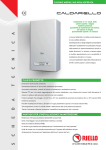
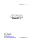
The following diagrams show the front and side views of
MicroScan, and its dimensions:
Figure 1: Front View of MicroScan
Figure 2: Side View of MicroScan
Introducing MicroScan
CHAPTER 1
3
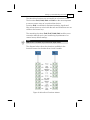
MicroScan Specifications
Accuracy
0.25%* of measuring range
Resolution
1 mm (0.04")
Beam angle
5° @ 3db point
Ambient temp’
compensation
Automatic
* 0.25% or 1.25cm whichever is greater.
Measuring Ranges
MicroScan L for liquids
0.25 m — 5 m
0.8 ft — 16.4 ft
MicroScan S for solids
0.25 m — 3.5 m
0.8 ft — 11.5 ft
Mechanical Specifications
Enclosure
IP 65, mono-block construction.
Plastic enclosure: ABS+UV
Wetted parts
Sensor body: PolyProp. PVDF, optional.
Stainless Steel for Liquid model; Coated
Aluminum for Solid/Liquid model.
Operating
temperature
-40° C to + 70° C
(-40° F to +158° F)
Mounting
2" BSP or 2" NPT
4
MicroScan User’s Manual
Mechanical fitting
Conduit connection M20x2.5 or
1/2" NPT
Operating pressure
Atmospheric
Dimensions
22.3 x 11 x 4.5cm (8.7 x 4.3x 1.7in)
Weight
Approx. 0.75Kg (1.65lb)
Electrical Specifications
Optional Display
LCD, four digits, seven segments
Operation
Four push buttons
Loop current
4 — 20 mA, 750 Ω @ 28 VDC
Supply
12 — 28 VDC (CE certified)
Certificates
CE — EMC
MSU Specifications
Display
LCD (4 digits — 7 segments)
Keyboard
4 buttons
Cable
0.60m (23.6in)
Housing material
ABS + UV
Dimensions
9.5X11X2.5cm (3.7X4.3X0.98 in)
Weight
0.25 Kg (0.55 lb)
Certifications
CE
Introducing MicroScan
CHAPTER 1
5
Sensor Recommendations
Material
Description
Stainless Steel
For liquid applications.
High resistance in highly
acidic and alcoholic
environments.
Less sensitive to echoes (in
Solid applications).
Coated Aluminum
Designed for complex
environments with
problematic echoes, such as
non-conductive vapors, solids
or liquids.
Good performance in
problematic applications.
High sensitivity to echoes.
6
MicroScan User’s Manual
Chapter 2
Installing MicroScan
Precautions
) Ensure that MicroScan is mounted in an area that meets the
stated temperature, pressure and technical specifications.
) Ensure that high-voltage sources or cables are at least 1 m away
from the sensor and its cable.
) Use a conduit connector that is either 1/2" NPT or M20x2.5
compatible (depending on the MicroScan model you have), to
ensure the unit remains sealed.
) Use 26-16 AWG round wires for the MicroScan’s electrical
connections.
) Ensure that cables are routed correctly and tightened along walls
or pipes.
) Installation and operation of this product should be performed,
according to the Product User Manual and Product Certification,
otherwise the use of this product is prohibited.
Installing MicroScan
CHAPTER 2
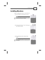
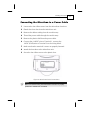
Installing MicroScan
When installing MicroScan, ensure that it is:
) Mounted above the dead-zone area.
NOTE:
If the device enters the blocking distance (dead
zone), it will not measure correctly.
) Positioned at least 0.5 m (1.64 ft) away
from the tank walls.
) Perpendicular to the surface of the
target.
NOTE:
Even the slightest difference in angle may affect
echo quality.
7
8
MicroScan User’s Manual
) Placed as far as possible from noisy
areas, such as a filling inlet.
Installing MicroScan on Threaded
Flange/Thread-Free Flange
MicroScan is available in two thread types, 2" BSP or 2" NPT.
MicroScan can be installed with threaded-flange mounting or
with thread-free flange mounting, as shown below:
Figure 3: Threaded Flange/Thread-Free Flange Mounting
Installing MicroScan
CHAPTER 2
9
NOTES:
When installing a thread-free flange mounted unit, you will need a 2"
locking nut to secure the unit inside the tank.
When installing a threaded flange, ensure that it matches the MicroScan
threads.
¾
To install MicroScan:
1
Insert the threaded end of MicroScan into the aperture at
the top of the tank or pipe.
2
Bolt MicroScan into place in one of the following ways:
) Threaded-flange mounting: Screw the unit into a
flange with a threaded 2" hole.
) Thread-free mounting: Place MicroScan in the flange,
and bolt it from within the tank with a 2" locking nut.
NOTES:
Tighten the nut by hand only. When tightening the nut, hold the
sensor housing (refrain from holding the MicroScan unit when
tightening the nut).Make sure that the seal is leak proof.
10
MicroScan User’s Manual
Installing MicroScan via Extension
Pipes
If the level of the measured surface falls within the dead-zone
area, you should use an extension pipe to mount MicroScan.
When using an extension pipe, ensure that:
) The sensor is positioned in the center of
the pipe.
) The pipe extension is parallel to the
side/tank walls.
) The internal pipe diameter is at least 3"
wide.
When installing the MicroScan with extension pipes, follow
these specifications:
Pipe Length
Internal Pipe Diameter
0.50 m (1.64 ft)
3"
1 m (3.28 ft)
3"
NOTE:
It is always recommended to use interference signal feature (Pr.03)
to locate interfering signals when using an extension pipe.
It is highly recommended that the extension pipes material would
be PVC or Plastic and not Stainless Steel.
Installing MicroScan
CHAPTER 2
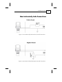
Connecting the MicroScan to a Power Cable
1
Unscrew the four Allen screws from the MicroScan front door.
2
Detach the front door from the MicroScan unit.
3
Remove the rubber sealing from the conduit entry.
4
Thread the power cable through the conduit entry.
5
Remove the plastic shell from the power cable.
6
Connect the +24VDC wire to Terminal 1, connect the
0VDC (GND) wire to Terminal 2 on the wiring block.
7
Make sure that the terminals’ screws are properly fastened.
8
Attach the front door to the MicroScan unit.
9
Screw the four Allen screws to the plastic door.
Figure 4: MicroScan Power Connections
NOTE:
Make sure that the O-Ring of the MicroScan's front door is properly
positioned to maintain the unit sealed.
11
12
MicroScan User’s Manual
Connecting the MicroScan to the MSU
(MicroScan Setup Unit)
The MSU is an hand held device which enables you to
configure the MicroScan unit according to your application
requirements, quickly and simply. Once the MicroScan unit
configuration is completed, the MSU can be utilized to
configure other MicroScan units.
The MSU should be connected to the MicroScan unit after
connecting the unit to a power supply.
1
Remove the plastic cap from the MSU connector located
on the MicroScan unit (the cap is chained to the
MicroScan unit).
2
Remove the plastic cover from the MSU multi-pin
connector.
3
Attach the MSU male connector to the female connector
on the MicroScan unit, located on its left side panel.
4
Make sure that the connectors are in the right position
and properly attached.
5
Rotate the plastic clasp on the MSU connector, half way
to the right, to ensure the connectors are firmly closed.
Figure 4.1: MSU Communication Connector
Installing MicroScan
CHAPTER 2
Non-Intrinsically Safe Connections
Figure 5: Non-Intrinsically Safe Positive Ground Connection
Figure 6: Non-Intrinsically Safe Negative Ground Connection
13
14
MicroScan User’s Manual
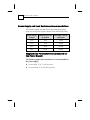
Power Supply and Load Resistance Recommendations
The following table specifies the recommended resistance
range for each power supply voltage (Non-Intrinsically Safe).
Power Supply
Voltage
Minimum Current
on Resistor
Maximum Current
on Resistor
12 V
0Ω
50 Ω
15 V
0Ω
220 Ω
24 V
41 Ω
610 Ω
28 V
68 Ω
820 Ω
Ripple/Noise Parameters Recommended for
the Power Supply
The following ripple/noise parameters are recommended for
the power supply:
) For less than 15 V: 75 mV p-p max
) For more than 15 V: 100 mV p-p max
Setting Up and Calibrating MicroScan
CHAPTER 3
15
Chapter 3
Setting Up and
Calibrating MicroScan
This chapter explains how to set up and calibrate MicroScan
for accurate measurement monitoring.
MicroScan is supplied with preprogrammed default settings,
making it ready for immediate operation. There is no need to
change the default settings, unless you wish to calibrate
MicroScan for your specific requirements; however, it is
recommended that you replace the default tank height value
with the actual tank height, as described on page 21. When
using MicroScan, the tank height is calculated as the distance
from the surface of the sensor to the bottom of the tank. You
should enter this value whenever tank height is required.
MicroScan contains nine programs, referred to as functions,
which enable you to change the default settings and calibrate
MicroScan as required. Changing the setting is available
using the MicroScan Setup Unit (MSU). The MSU is a hand
held device that enables you to enter the MicroScan
functions and menus and set it up according to your
application requirements. You can use the MSU to calibrate
numerous MicroScan units in the field.
16
MicroScan User’s Manual
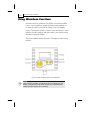
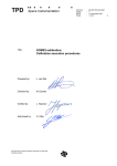
To facilitate the MicroScan unit set-up and configuration, mount
the MSU on top of the unit, placing its four plastics pins on board
the four screw holes of the MicroScan’s front door, as illustrated
below. Make sure that the MSU is properly situated on the
MicroScan unit.
Figure 7: MSU mounted on the MicroScan unit
Setting Up and Calibrating MicroScan
CHAPTER 3
17
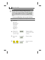
The MicroScan functions are accessed from a functions menu.
The functions Pr01, Pr02, Pr04 and Pr05 are the most important
to ensure correct usage of your MicroScan device.
Function Pr03 is essential to eliminate interfering signals and
false echoes that may exist inside the tank and sometimes are not
visible to the human eye.
The remaining functions (Pr06, Pr07, Pr08, Pr09) enable you to
customize MicroScan for your monitoring requirements or to
restore factory default settings.
NOTE:
Pr06 function is available only for MicroScan liquid models.
The diagram below shows the functions available in the
functions menus for the MicroScan L and S models.
Figure 8: MicroScan Functions Menus
18
MicroScan User’s Manual
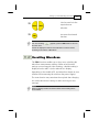
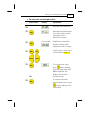
Using MicroScan Functions
MicroScan has an optional LCD display screen that enables
you to view continuous updated measurement readings, or
by using the MSU’s (MicroScan Setup Unit) LCD display
screen. The display screen is used to view MicroScan’s menu
options, function settings and data values, accessed by using
the MSU’s function buttons.
The picture below shows the MSU LCD display and function
buttons:
Figure 9: MSU Display and Function Buttons
NOTE:
When mounting the MSU on a MicroScan unit incorporating an LCD
display, measurement results will be viewed only on the MicroScan
display (the MSU' display will not function).
Setting Up and Calibrating MicroScan
CHAPTER 3
The function buttons are used to perform various operations,
summarized in the following table.
Button
Uses Include:
) Accessing the functions menu (when
pressed simultaneously with
)
) Selecting functions
) Progressing to the next step of a function
) Moving from left to right between
displayed digits (see note on the following
page)
) Saving changes to data
) Accessing the functions menu (when
pressed simultaneously with
)
) Exiting the functions menu to restore the
distance reading
) Moving from right to left between
displayed digits (see note on following
page)
) Exiting a function without saving changes
) Clearing error messages
) Scrolling through the functions menu
or
) Scrolling through available data values in
functions
) NEXT button only: Recording interfering
signals (see page 24)
19
20
MicroScan User’s Manual
NOTE:
Within some functions, the digits in the displayed value can be
individually modified. This is indicated by a flashing digit (flashing digits
are shown in gray in the display illustrations, for example,
). In
this case, the ENT and ESC buttons enable you to move between the
digits. Each flashing digit can be modified using the BACK and NEXT
buttons.
¾
To start up MicroScan and access the functions:
Press/Action
>
Connect the
MSU to the
MicroScan unit
(following the
connection
instructions
described on
Chapter 2.)
>
Connect the
MicroScan unit
to power supply
>
After a brief
pause
>
and
(simultaneously)
Display
Explanation
Temporary display
while MicroScan takes
a reading.
For example:
Distance reading.
For example:
Enters the functions
menu.
Setting Up and Calibrating MicroScan
CHAPTER 3
>
21
Used to search for the
required menu
selection.
or
>
Accesses the selected
function.
NOTES:
If an error message
the main menu.
appears, press the ESC button to return to
Values are displayed in meters and centimeters or feet and inches,
according to the version of MicroScan.
Resetting MicroScan
The PR01 function enables you to do a reset, refreshing the
MicroScan measurement reading. (Other saved function
settings are not changed.) After resetting, a default reading is
displayed on the MSU’s (or the MicroScan’s display,
depending on the model) LCD, and MicroScan begins to scan
(similar to disconnecting the unit from the power supply.)
The reset function may sometimes be required after changing
one of the MicroScan’s settings or after receiving an error
message.
NOTE:
When the display shows 8.8.8.8 the 4-20mA current reading will be
around 28mA.
22
MicroScan User’s Manual
¾
To reset MicroScan:
Press/Action
Display
Explanation
>
Required menu
selection.
>
Temporary display while
MicroScan takes reading.
>
>
After a brief
pause
and
(simultaneously)
For example,
Distance reading.
Returns to the functions
menu.
Entering the Tank Height Value
The Pr02 function enables you to enter the tank height. The
default value is the highest value in the relevant
measurement range for your model. If you enter a value that
exceeds this highest value, the Err error message is displayed
and the value is not saved.
NOTES:
Whenever the tank height is required, you should enter the distance from
the surface of the sensors to the bottom of the tank.
The first digit can be modified to read between 0 and 1 for metric units or
between 0 and 5 for feet units.
Setting Up and Calibrating MicroScan
CHAPTER 3
¾
23
To enter the tank height value:
Press/Action
Display
Explanation
>
Required menu selection.
>
Indicates the measurement
unit, either meters or feet
(according to the
MicroScan version).
>
For example
>
or
Displays last saved tank
height or default value
(maximum value in range).
Used to enter a new value,
as described on page 19.
or
>
To save the new value,
OR
>
when standing
press
on the far-right digit. After
YES is displayed, the
display returns to the
functions menu.
To return to the main
menu without saving, press
when standing on the
far-left digit.
24
MicroScan User’s Manual
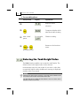
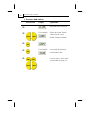
Defining Interfering Signals
The Pr03 function enables you to locate and store up to four
interfering signals (false echoes) in the MicroScan memory, to
avoid having obstructions such as a tank agitator, sidewall or
any other obstructions that are not visible to the human eye
and may interfere with the measurement of the contents. This
function is essential to obtain accurate measurement results
and therefore it must be activated prior to the completion of
the unit’s installation. Defining interfering signals should be
done while the tank is empty.
Figure 10: Scan Distance Process
Setting Up and Calibrating MicroScan
CHAPTER 3
25
Each reading (scan distance) taken using the Pr03 function is
stored as an interfering signal, until a reading is achieved that
indicates the real echo. If four interfering signals are already
stored and a fifth value is entered, the first value stored is
deleted and the new one saved.
NOTES:
The reading of the actual target height may not be exact, for example, a
target height of 4m may give a reading in the range 3.98 - 4.02.
The displayed values are in distance units.
¾
To define interfering signals:
Press/Action
Display
>
Required menu selection.
>
Select Search to locate
acoustic interferences, or
Clear to delete stored
interferences.
or
>
Displayed after the
selection for 3 seconds and
then the menu returns to
Pr.03.
>
>
Explanation
Temporary display while
MicroScan searches for
interfering signals.
After a brief
pause
For example,
Depth to interfering signal.
26
MicroScan User’s Manual
Press/Action
Display
>
>
>
Explanation
Saves the interfering signal,
then searches again and
displays the next reading.
Continue to press this
button to save up to four
interference readings.
For example,
Actual target height reading
indicates that there are no
more interfering signals.
Saves the entered values.
NOTES:
If the value represents an interference or false echo or false target press NEXT. If the value represents the real target, real distance –
press ENT.
Setting Up and Calibrating MicroScan
CHAPTER 3
27
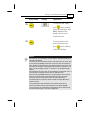
Configuring 4mA Current Output
Pr04 function enables you to enter values to be used as the
4mA mark for remote monitoring. You can define the 4mA
values for Level or Distance measurements. The
measurement values types should be defined in Pr.04. These
definitions will be applicable for the 20mA values defined in
Pr.05 as well. Distance and level measurements can be
defined for both Solid and Liquid MicroScan models.
To set 4mA and 20mA for level measurements you should
configure Pr04 and Pr05 for level values.
For example, if we measure a tank with tank height
configured for 4 meters, the 4mA values will represent zero
tank level and 20mA values will represent full tank level.
Therefore, the value entered in Pr04 will be 0.000m and the
value entered in Pr05 will be 4.000m.
When setting 4mA and 20mA for distance measurements,
4mA values will represent the minimal distance between the
surface of the target and the sensor and 20mA values will
represent the maximal distance between the sensor and the
surface of the target. Therefore, 4mA and 20mA in this mode
represent the empty part of the tank.
28
MicroScan User’s Manual
¾
To enter 4mA values:
Press/Action
Display
>
Explanation
Required menu selection.
>
For example,
Select 4mA (and 20mA)
values format: Level
(L000), Distance (d000).
For example
Last saved 4mA level or
zero default value.
or
>
>
>
or
or
Used to enter a new value,
as described on page 19.
Setting Up and Calibrating MicroScan
CHAPTER 3
Press/Action
>
Display
29
Explanation
To save the new value,
when standing
press
on the far-right digit. After
YES is displayed, the
display returns to the
functions menu.
>
To return to the main
menu without saving,
press
when standing
on the far-left digit.
NOTES:
The values for 4mA and 20mA must be different; otherwise an Err error
message is displayed.
The values for 4mA and 20mA should not be higher than the value used
for the tank height (Pr02), and should not be lower than the dead-zone
value. Because of the dead-zone, the distance between the sensor and
the surface of the target at its highest level should be a minimum of 0.6
ft/0.2 m for Short-Range models, or 1.96 ft/0.6 m for Standard-Range
models.
The first digit of the 4mA value can be modified to read between 0 and 1
for metric units or between 0 and 5 for U.S. Standard units.
After accessing the Pr04 function, the unit generates a fixed current of
22mA on the 4-20mA line. When the MicroScan reverts to regular
scanning mode, the 4-20mA line returns to regular functioning.
The default values for 4mA and 20mA in Solid and Liquid MicroScan
models are level.
The measurement mode selected for the 4-20mA values will not
influence the measurement mode selected for the display (Pr.08).
In case of power rest, measurement configuration (level, distance) will
be saved according to the unit's last configuration.
30
MicroScan User’s Manual
Configuring 20mA Current Output
The Pr05 function enables you to enter values to be used as
the 20mA mark for remote monitoring.
¾
To enter 20mA values:
Press/Action
Display
>
Explanation
Required menu selection.
>
>
For
example
>
or
Last saved 20mA level or
default value (maximum
value in range).
Used to enter a new value, as
described on page 24.
or
>
To save the new value, press
when standing on the
far-right digit. After YES is
displayed, the display returns
to the functions menu.
OR
Setting Up and Calibrating MicroScan
CHAPTER 3
Press/Action
>
Display
31
Explanation
To return to the main menu
without saving, press
when standing on the far-left
digit.
NOTES:
Type of measurement (level, distance) selected in Pr.04 is also
applicable for Pr.05.
The values for 4mA and 20mA must be different; otherwise an Err error
message is displayed.
The values for 4mA and 20mA should not be higher than the value used
for the tank height (Pr02), and should not be lower than the dead-zone
value.
The first digit of the 20mA value can be modified to read between 0 and
1 for metric units or between 0 and 5 for U.S. Standard units.
After accessing the Pr05 function, the unit generates a fixed current of
22mA on the 4-20mA line.
When the MicroScan reverts to regular scanning mode, the 4-20mA line
returns to regular functioning.
Please refer to chapter 4 "Troubleshooting" for 22mA error indications.
32
MicroScan User’s Manual
Selecting Low/High Dynamic
Speed (Liquid Only)
The Pr06 function enables you to choose the required speed
and accuracy level. There are two settings available:
) SE 0: Low dynamic mode (default setting). This mode
enables more accurate measurements resulting in a
slower filling rate.
) SE 1: High dynamic mode. This mode enables a faster
filling rate, providing less accurate measurement results.
¾
To select the speed mode:
Press/Action
Display
Explanation
>
Required menu selection.
>
Displays the current
operation mode setting.
or
>
Used to toggle between the
operations modes.
or
>
Saves the selected
operation mode.
Setting Up and Calibrating MicroScan
CHAPTER 3
33
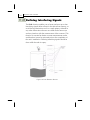
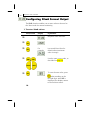
Defining Working Area
The Pr07 function allows you to add distance range that
exceeds the tank’s height, thus enabling accurate readings of
complicated tank shapes with conic ending. This may be
required when the vessel has a conical bottom shape which
is causing false echoes and consequently faulty
measurements. The entered range can be from the minimum
tank height to twice the maximum measuring range of the
MicroScan (depending on the MicroScan model). The default
setting is the entered tank height.
Figure 11: Defining Working Area
34
MicroScan User’s Manual
¾
To define a Working Area:
Press/Action
Display
Explanation
>
Required menu selection.
>
Displayed when entering
the function.
>
>
for example:
or
Displays the value last
saved in the tank height
(default). To overcome
conical shaped tanks, enter
a value that is up to double
the tank height. The entered
value should not be more
than double the tank height
and should not exceed the
MicroScan’s maximum
measuring range.
Used to enter a new value,
as described on page 19.
or
>
Saves the entered value.
Setting Up and Calibrating MicroScan
CHAPTER 3
Press/Action
Display
>
35
Explanation
Used to move on to the
next function.
or
NOTE:
It is recommended to use the Pr.07 function only in Distance
mode.
Selecting Distance or Level
Display
The Pr08 function enables you to view either distance or
level measurements on the MSU or MicroScan LCD display
(depending on the model).
There are two settings available:
) d000: Distance mode (default setting): In this mode,
MicroScan displays the distance from the sensor to
the surface of the contents.
) L000: Level mode: In this mode, MicroScan displays
the level of the contents from the bottom of the tank.
NOTE:
The measurement mode selected for the display will not influence the
measurement mode selected for the 4-20mA values (Pr.04).
36
MicroScan User’s Manual
¾
To select distance or level display:
Press/Action
Display
Explanation
>
Required menu selection.
>
Displays the current
distance/level mode setting.
or
>
Used to toggle between the
modes.
or
>
Saves the selected mode.
Setting Up and Calibrating MicroScan
CHAPTER 3
37
Restoring the Default Settings
The Pr09 function allows you to clear all user-defined
settings and revert to the default factory settings.
NOTE:
If you decide that you do not want to revert to the default settings, press
ESC when CLCL is displayed. A redo option is not available when ENT
has been pressed.
¾
To restore the default settings:
Press/Action
>
Display
Explanation
Required menu selection.
>
>
Reverts all settings to
default factory settings.
38
MicroScan User’s Manual
Shifting the Blocking Distance
This function enables you to define an area in which
measurement results would be ignored. This option is
applicable for installations requiring extension pipes or
nuzzles positioned above the material level. This area should
fit the pipe/nuzzle length to eliminate false echoes and to
provide accurate and stable measurement readings.
¾
To shift the blocking distance:
Follow the directions given for Entering the Tank Height
Value, page 22. Instead of entering the tank height value,
enter 00.01, and continue as follows:
Press/Action
Display
Explanation
>
Insert this code to enter the
Blocking Distance area.
>
This message will flash for a
few seconds, indicating an
entry to the Blocking
Distance area.
For example,
To shift the blocking
distance to 0.75m (2.46 ft).
or
>
To save this entry and
return to Pr.02.
NOTES:
The Blocking Distance shifting is limited to 1.5m/4.9ft.
Echo received from the defined Blocking Distance area will be ignored by the
MicroScan and the measurement result will be based on the next echo.
Pr.09 (Clear) will revert the blocking distance to its default.
Setting Up and Calibrating MicroScan
CHAPTER 3
39
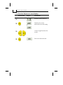
Verifying the Version Number
In addition to the functions described, you can verify the
MicroScan version number.
¾
To verify the MicroScan version number:
Follow the directions given for Entering the Tank Height
Value, page 22. Instead of entering the tank height value,
enter 00.17, and continue as follows:
Press/Action
Display
Explanation
>
>
>
After a brief
pause
Displays the version
number.
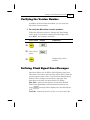
Defining 22mA Signal Error Messages
MicroScan allows you to define if the following signal error
indications: Near Zone and Lost Echo will be active when the
current output reaches 22mA. The MicroScan default setting
disables 22mA analog current and error messages from
appearing on the MSU (or MicroScan) LCD display.
Near Zone - whenever the distance is below the defined
Dead Zone (depending on the MicroScan model you are
message will be displayed on the MicroScan’s
using)
LCD.
Lost Echo - whenever the echo is lost, or in cases when the
40
MicroScan User’s Manual
measurement results exceed the tank height or when a
message will be
returned echo is not received
displayed on the MSU (or MicroScan) LCD.
You can choose to enable or disable these error messages
and 22mA analog signal as follows:
) d000: Disable (default setting)
) E000: Enable
Refer to Chapter 4, Troubleshooting for a detailed list of the
22mA signal error messages.
¾
To enable 22mA signal error in the MicroScan:
Follow the directions given for Entering the Tank Height
Value, page 22. Instead of entering the tank height value,
enter 00.16, and continue as follows:
Press/Action
Display
Explanation
>
Choose enable (or disable).
>
Used to toggle between the
modes.
or
>
Enables the 22mA error
messages.
Troubleshooting MicroScan
CHAPTER 4
41
Chapter 4
Troubleshooting
MicroScan
This chapter describes how to resolve problems that may
occur when calibrating MicroScan, as follows:
Error
Description
Solution
Noise in area.
Check that the power
supply is appropriate.
Faulty power supply.
Make sure that the power
supply corresponds with
the specifications described
in Chapter 2, Installing
MicroScan. If the problem
persists, replace the power
supply.
Sensor disconnected.
Contact the distributor for
further instructions.
Any combination of three 8s
and one 1: Indicates an
electrical shortage caused by
depressing the buttons for
too long.
Contact the distributor for
further instructions.
42
MicroScan User’s Manual
Appears for several seconds
after restarting the unit. If it
is displayed for more than
several seconds, it may be
due to one of the following:
) Power supply voltage is
too low
Make sure that the power
supply corresponds with the
specifications described in
Chapter 2, Installing
MicroScan. If the problem
persists, replace the power
supply.
) Load resistor resistance is
too high or unnecessary
) A random pulse that
causes the unit to
automatically restart
22mA Signal Error Messages
The following list of messages will appear on the display and
coincides with a 22mA analog current error output signal:
Error
Description
Solution
Sensor disconnected.
Contact the distributor
for further instructions.
Near dead zone.
Move the sensor farther
from the dead zone
area.
Tank empty.
Check the level of
material in the tank.
Noise in area.
Check that the power
supply is appropriate.
Troubleshooting MicroScan
CHAPTER 4
Faulty power supply.
43
Make sure that the
power supply
corresponds with the
specifications
described in Chapter 2,
Installing MicroScan. If
the problem persists,
replace the power
supply.
44
MicroScan User’s Manual
Index
2
20 mA mark, 32
F
False echoes, 28
4
Function buttons, 22
Functions
accessing, 24
4 mA mark, 30
B
menu, 24
H
Blocking distance shift, 38
High dynamic setting, 34
Buttons
function, 22
I
D
Installing
MicroScan, 7
Default settings
threaded-flange mounting, 8
restoring, 40
Defining working area, 35
thread-free flange mounting, 8
Defining 22mA signal error messages,
via extension pipes, 10
Interfering signals, 28
41
Intrinsically safe
Dimensions, 2
Distance measurement display, 36
ground connections, 15
Dynamic
power supply, 19
low/high speed, 34
E
Electrical specifications, 4
Entering factor for gas compensation,
38
L
Level measurement display, 36
Load resistance recommendations, 14,
19
Low dynamic setting, 34
Index
M
Restoring default settings, 40
Ripple/noise parameters, 14
Measurement
S
distance display, 36
level display, 36
Measuring
45
Sensors
recommended types, 5
ranges, 3
Setting up, 20
Mechanical specifications, 4
MicroScan
Settings
restoring default, 40
dimensions, 2
Shift blocking distance, 38
measuring ranges, 3
Signals
models, 1
interfering, 28
resetting, 25
Signal error messages, 41
setting up, 20
Specifications, 3
specifications, 3
N
electrical, 4
mechanical, 4
Speed mode, 34
Non-intrinsically safe
T
ground connections, 13
power supply, 14
P
Power supply
Table for gas compensaion factor, 67
Tank height value, 26
Trapezoidal (Cipolletti) Sharp-Crested
Weir, 48, 58
recommendations, 14, 19
Troubleshooting, 64
ripple/noise parameters, 14
V
Precautions, 6
R
Remote monitoring
20 mA, 32
Version number
displaying, 41
W
4 mA, 30
Resetting MicroScan, 25
Working Area, 35