1
TPD
Space Instrumentation
DOC.NO.
ISSUE
DATE
PAGE
Title:
GOME2-calibration:
Calibration execution procedures
Prepared by:
L. van Riel
Checked by:
M. Eschen
Verified by:
J. Hopman
Authorised by:
G. Otter
This document contains proprietary information of TNO-TPD.
All rights reserved.
:
:
:
:
MO-PR-TPD-GO-0027
4
11 November 2002
1 of 25
TPD
DOC.NO.
ISSUE
DATE
PAGE
Space Instrumentation
:
:
:
:
MO-PR-TPD-GO-0027
4
11 November 2002
2 of 25
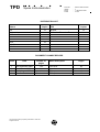
DISTRIBUTION LIST
Others
Copies
OG
R. Veratti
B. Ricciarelli
1x
ESA
A. Lefèbvre
J. Callies
1x
TPD
Copies
Archive
Calibration Execution Team
1x
1x
DOCUMENT CHANGE RECORD
Issue
Date
Number of
pages
1
2
3
4
20 September 2000
11 March 2002
16 August 2002
See header
1-23
26
See header
This document contains proprietary information of TNO-TPD.
All rights reserved.
Short description
First issue
New document
FM1 update
FM2 update
Pages
All
All
All
All
TPD
Space Instrumentation
DOC.NO.
ISSUE
DATE
PAGE
:
:
:
:
MO-PR-TPD-GO-0027
4
11 November 2002
3 of 25
Table of Contents
1.
SCOPE ..................................................................................................................................................................... 5
2.
DOCUMENTS AND ACRONYMS....................................................................................................................... 6
2.1
2.2
2.3
3.
APPLICABLE DOCUMENTS.................................................................................................................................. 6
REFERENCE DOCUMENTS .................................................................................................................................. 6
ACRONYMS ....................................................................................................................................................... 6
SUPPORTING PROCEDURES APPLICABLE DURING CALIBRATION EXECUTION........................... 8
3.1
OPERATION AND HANDLING PROCEDURE.......................................................................................................... 8
3.2
EMERGENCY PROCEDURE ................................................................................................................................. 8
3.3
ALIGNMENT PROCEDURE STIMULI AND MGSE ................................................................................................. 8
3.4
OPERATION OF TVC.......................................................................................................................................... 8
3.5
SWITCH ON/OFF PROCEDURE FOR GOME2 (GAL ATP’S) .................................................................................. 8
3.5.1 Switch on procedure for Gome 2 ................................................................................................................. 8
3.5.2 Change_context.tal .................................................................................................................................... 10
3.5.3 History_decoder.tal ................................................................................................................................... 10
3.5.4 Switch off procedure for Gome 2 ............................................................................................................... 10
3.6
GOME2 CONSOLE ............................................................................................................................................ 11
3.7
RUNNING ATP'S .............................................................................................................................................. 11
3.8
LOGGING ......................................................................................................................................................... 12
3.9
BACK UP OF DAPB DATA................................................................................................................................ 13
3.10
QUICK LOOK ................................................................................................................................................... 13
3.11
LVM MONITORING.......................................................................................................................................... 13
4.
STEP-BY-STEP PROCEDURE .......................................................................................................................... 14
4.1
GENERAL ........................................................................................................................................................ 14
4.2
PREPARATIONS ................................................................................................................................................ 15
4.3
AMBIENT BLOCK 1 .......................................................................................................................................... 15
4.4
AMBIENT BLOCK 2 .......................................................................................................................................... 15
4.5
INSTALL GOME2 IN TVC ............................................................................................................................... 16
4.6
TVC/GOME TB2 (NOMINAL TEMP) CAMPAIGN ............................................................................................... 16
4.6.1 Gome.......................................................................................................................................................... 16
4.6.2 LRS in White light mode............................................................................................................................. 17
4.6.3 LRS in filter mode (TB2) ............................................................................................................................ 17
4.6.4 LRS in slit mode (TB2) ............................................................................................................................... 17
4.6.5 LRS in monochromator mode (TB2) .......................................................................................................... 17
4.6.6 HCL stimulus (TB2) ................................................................................................................................... 17
4.6.7 ORIEL stimulus (TB2)................................................................................................................................ 17
4.6.8 Zenith sky measurements (TB2) ................................................................................................................. 18
4.6.9 Rad/Irrad in sun mode (TB2) and Sun simulator at nadir (TB2).............................................................. 18
4.6.10
Rad/Irrad in nadir mode (TB2) and Sun simulator at sun (TB2)........................................................... 18
This document contains proprietary information of TNO-TPD.
All rights reserved.
TPD
Space Instrumentation
DOC.NO.
ISSUE
DATE
PAGE
:
:
:
:
MO-PR-TPD-GO-0027
4
11 November 2002
4 of 25
4.6.11
Sphere in nadir (TB2) ............................................................................................................................ 18
4.7
TVC/GOME TB1 (NOMINAL-10 TEMP) CAMPAIGN .......................................................................................... 18
4.7.1 LRS in white light mode (TB1)................................................................................................................... 19
4.7.2 Oriel stimulus (TB1)................................................................................................................................... 19
4.7.3 HCL stimulus (TB1) ................................................................................................................................... 19
4.7.4 Rad/Irrad in sun mode (TB1) and Sun simulator at nadir (TB1)............................................................... 19
4.7.5 Rad/Irrad in nadir mode (TB1) and Sun simulator at sun (TB1)............................................................... 19
4.8
TVC/GOME TB3 (NOMINAL+10 TEMP) CAMPAIGN ......................................................................................... 19
4.8.1 LRS in white light mode (TB1)................................................................................................................... 20
4.8.2 HCL stimulus ............................................................................................................................................. 20
4.8.3 Oriel stimulus (TB3)................................................................................................................................... 20
4.8.4 Rad/Irrad in sun mode (TB3) and Sun simulator at nadir (TB3)............................................................... 20
4.8.5 Rad/Irrad in nadir mode (TB3) and Sun simulator at sun (TB3)............................................................... 20
4.9
CATGAS MEASUREMENTS AT TB2 ................................................................................................................ 21
4.10
POST TEST AND PACKING ................................................................................................................................. 21
4.11
NON-CONFORMANCE REPORTING.................................................................................................................... 22
4.12
DEVIATIONS FROM THE PROCEDURE ............................................................................................................... 22
5.
PROCEDURE SIGN-OFF SHEET ..................................................................................................................... 23
6.
PROCEDURE VARIATION SHEET ................................................................................................................. 24
7.
GOME 2 NCR'S AFFECTING CALIBRATION EXECUTION (GAL INFO) .............................................. 25
This document contains proprietary information of TNO-TPD.
All rights reserved.
TPD
1.
Space Instrumentation
DOC.NO.
ISSUE
DATE
PAGE
:
:
:
:
MO-PR-TPD-GO-0027
4
11 November 2002
5 of 25
Scope
This document presents the calibration execution procedure including the step-by-step procedure
to be applied for the calibration of the Gome2 instrument.
This procedure is applicable for Gome2 FM1; FM2 and FM3
This document contains proprietary information of TNO-TPD.
All rights reserved.
TPD
Space Instrumentation
2.
Documents and Acronyms
2.1
Applicable documents
[AD1] Gome2 Calibration Requirements Specification
MO-RS-GAL-GO-0003
[AD2] Gome2 Calibration Plan
MO-PL-TPD-GO-0004
[AD3] Gome2 handling transportation and installation procedure
MO-PR-TPD-GO-0025, latest issue
[AD4] Gome2 emergency procedure for the VCF
MO-PR-TPD-GO-0029, latest issue
[AD5] Optical and mechanical alignment procedure
OPR020003
[AD6] List of applicable Gome2 FMx instrument NCR's
(To be provided by GAL)
[AD7] ATP report
MO-RP-TPD-GO-0037, latest issue
[AD8] TVC user manual
[AD9] Gome2 safety guideline for Calibration
MO-NT-GAL-GO-0025, latest issue
2.2
Reference documents
None
2.3
Acronyms
Acronym
AIRR
ATP
BEPNT
CTB
DAPB
EGSE
ESA
FMUSIM
FPA
GAL
Gome
GSE
HCL
LRS
LVM
MGSE
NCR
Description
Ambient Irradiance/Radiance set-up
Automated Test Procedure
ODBH Bus Probe, New Technology
Command and Telemetry Block
Data Acquisition and Processing Block
Electrical Ground Support Equipment
European Space Agency
Fast Multiplexer Unit Simulator
Focal Plane Assembly
Galileo Avionica
Global Ozone Monitoring Experiment
Ground Support Equipment
Hollow Cathode Lamp
Low Radiance Stimulus
Low Voltage Mode
Mechanical Ground Support Equipment
Non Conformance Report
This document contains proprietary information of TNO-TPD.
All rights reserved.
DOC.NO.
ISSUE
DATE
PAGE
:
:
:
:
MO-PR-TPD-GO-0027
4
11 November 2002
6 of 25
TPD
Acronym
OGSE
PMD
PVS
QTH
SMU
SLS
TBC/TBD
TVC
VCF
WLS
Xe
Space Instrumentation
Description
Optical Ground Support Equipment
Polarisation Measurement Device
Procedure Variation Sheet
Quartz Tungsten Hydrogen Lamp
Scan Mirror Unit
Spectral Light Source
To Be Confirmed / To Be Determined
Thermal Vacuum Chamber
Vacuum Calibration Facility
White Light Source
Xenon Lamp
This document contains proprietary information of TNO-TPD.
All rights reserved.
DOC.NO.
ISSUE
DATE
PAGE
:
:
:
:
MO-PR-TPD-GO-0027
4
11 November 2002
7 of 25
TPD
Space Instrumentation
DOC.NO.
ISSUE
DATE
PAGE
:
:
:
:
MO-PR-TPD-GO-0027
4
11 November 2002
8 of 25
3.
Supporting procedures applicable during Calibration Execution
3.1
Operation and Handling Procedure
[AD3] Gome2 handling transportation and installation procedure
MO-PR-TPD-GO-0025, latest issue
3.2
Emergency Procedure
[AD4] Gome2 emergency procedure for the VCF
MO-PR-TPD-GO-0029, latest issue
3.3
Alignment Procedure Stimuli and MGSE
[AD5] Optical and mechanical alignment procedure
OPR020003
3.4
Operation of TVC
[AD8] TVC user manual
3.5
Switch on/off procedure for Gome2 (GAL ATP’s)
3.5.1 Switch on procedure for Gome 2
step
description
turn 19" rack on
1.
set red switch to OFF (0)
2.
turn safety button at the bottom of the rack to the right
3.
turn on switch that is located directly above the safety button (should be directed upwards now)
4.
turn red switch to ON (1)
boot up the BEPNT
5.
push the power button on the rightmost PC (located under the desk)
6.
login as 'administrator'
7.
double-click icon 'start_bep.bat'
8.
double-click icon 'BEP MMI'
9.
wait for red indicators in the application window to become green
10.
check all "acquiring panel" checkboxes to ON
boot up FMUSIM
11.
push the power button on the leftmost PC (located under the desk)
12.
login as 'administrator'
13.
double-click icon 'FMU SIM MMI' (ignore error message "FMU SIM Core not present" --> OK)
14.
Start from menu bar: 'menu' --> 'core' --> 'start FMUSIM' (you have to click 'OK' twice)
15.
Start from menu bar: 'menu' --> 'core' --> 'connect to FMUSIM'
16.
in the application window, section 'panel', subsection 'input', click 'nominal 2'
17.
in the application window, section 'panel', subsection 'output', click 'nominal 1'
18.
in the application window, section 'panel', subsection 'commands', click 'acquisition on'
This document contains proprietary information of TNO-TPD.
All rights reserved.
TPD
Space Instrumentation
DOC.NO.
ISSUE
DATE
PAGE
step
description
19.
in the application window, section 'panel', subsection 'commands', click 'distribute on'
:
:
:
:
MO-PR-TPD-GO-0027
4
11 November 2002
9 of 25
check 19" rack
20.
all numbers in the digital displays should be close to zero
boot up CTB
21.
push the power button on the PC (located under desk)
22.
login as 'administrator',
23.
double-click icon 'GOME2 CTB_MMI'
24.
user: 'TPD_operator' ; working dir: 'GOME2FM2
25.
Start from menu bar: 'menu' --> 'modes' --> 'online' à ‘yes’
26.
Start from menu bar: 'menu' --> 'tools' --> 'ATP' --> 'start'
Checksum control
27.
Switch N and ICU on buttons on power supply (19” rack) on
28.
Switch on Gome with ATP “Power_on28”
29.
Run ATP “Low_level_p_d_c”
30.
Input: Operator name (use your initials for this) à ‘OK’
31.
Switch Off Gome with ATP “Power_supply_off”
32.
Control the values of the checksums in the ATP trace file, refer to [AD9]
33.
Switch on Gome with ATP: 'Og_start' (no parameters) (Og_start will now appear in ATP status window: should be
yellow now, i.e. the ATP is waiting)
34.
Input: N and ICU on buttons on power supply à’yes’
19” rack
35.
push buttons 'EQ ON' and 'ICU ON' lift cap, push button, close cap (do nothing if buttons are already green)
36.
ICU display should read:
+/- 28.00 V
+/- 0.43 A
37.
EQT display should read:
+/- 28.00 V
+/- 0.00 A
38.
Wait for approximately 1 minute
CTB
39.
Input: Operator name (use your initials for this) à ‘OK’
40.
Input: Context_FPA_cooling_enabled (y/n) à ‘n’ (safe mode) à ‘OK’
Be sure about yes (FPA vacuum on!).
Remark: use the console ATP for switching on FPA/PMD coolers
41.
Input: Context_PMD_cooling_enabled (y/n) à ‘n’ (safe mode) à ‘OK’
Be sure about yes (in vacuum only!)
42.
Input: Context_PMD_flight_line_enabled (y/n) à ‘n’ (safe mode) à ‘OK’
43.
Input: Context_QTH_high_current_enabled (y/n) à ‘n’ (=360 mA); ‘y’ (=420 mA TBC) à ‘OK’
44.
Input: Continue with BIT (y/n) à ‘n’à ‘OK’
BIT = Built In Test, this procedure does not work properly, results always in a failure, use checksum procedure
mentioned above instead
45.
Input: Choose monitoring (see log msg): 0,1,2 à ‘0’à ‘OK’
46.
Input: Choose mon.par set (0=air, 1=TV) à air or TV à ‘OK’
Use the appropriate parameter for the environment Gome is in
47.
Input: ATP 'Get_packet' in ATP status window. From the options 1=RTR, 2=RT, 3=RTE, select option 3 (i.e.
everything)
48.
Send Idle command (y/n) à ‘y’ à ‘OK’
This document contains proprietary information of TNO-TPD.
All rights reserved.
TPD
step
Space Instrumentation
DOC.NO.
ISSUE
DATE
PAGE
:
:
:
:
MO-PR-TPD-GO-0027
4
11 November 2002
10 of 25
description
DAPB
49.
push the power button on the DAPB (below desk)
50.
login and password are not needed
51.
double-click icon 'GOME-2 DAPB Version 1.xx'
52.
verify/set values in the DAPB start-up window:
Station type:
DAPB-1
Instrument model:
FM1 (1, 2 or 3)
Level:
INSTRUMENT
Company:
TPD
User:
EZ
Session description.:
short description of measurement, this description will appear in data file name
The subsystems are now ready for running calibration ATPs
3.5.2 Change_context.tal
A GAL ATP for switching on/off FPA and PMD coolers. Use preferably the console.tal
3.5.3 History_decoder.tal
An GAL ATP for resetting the history decoder. This ATP is used for monitoring anomalies. This
ATP shall be frequently executed (at least after each ATP)
3.5.4 Switch off procedure for Gome 2
step
description
shut down CTB
1.
start ATP 'OG_stop' (menu bar: 'menu' --> 'tools' --> 'ATP' --> 'start')
2.
wait for all ATP's to be stopped
3.
set CTB to local mode: ('menu' --> 'modes' --> 'local')
4.
exit CTB application: ('menu' --> 'file' --> 'exit')
5.
shutdown CTB computer (power switch under the desk)
turn off 19" rack
6.
set red switch to OFF (0)
7.
turn OFF the switch located directly above the big red safety button (should be directed downward now)
8.
turn big red safety button to the left
shut down FMUSIM
9.
stop FMUSIM core ('menu' --> 'core' --> 'stop FMUSIM core' ; OK)
10.
close FMUSIM application ('menu' --> 'file' --> 'close program')
11.
shutdown FMUSIM computer (power switch under desk)
shutdown BEPNT
12.
close BEPNT application ('menu' --> 'file' --> 'exit')
13.
shutdown BEPNT computer (power switch under desk)
This document contains proprietary information of TNO-TPD.
All rights reserved.
TPD
3.6
Space Instrumentation
DOC.NO.
ISSUE
DATE
PAGE
:
:
:
:
MO-PR-TPD-GO-0027
4
11 November 2002
11 of 25
Gome2 console
This feature comprises initialisation/de-initialisation commands for Gome2, such as: FPA/PMD
coolers on/off, set SMU angle etc.
The following procedure/settings are applicable (TBC):
1. Start Gome2_console.atp (see section 3.7)
2. Enter SMU angle [°]
3. Enter code for:
200
Gome2 LED FPA off
201
Gome2 LED FPA on
300
Gome2 LED PMD off
301
Gome2 LED PMD on
400
Gome2 SLS off
401
Gome2 SLS on
500
Gome2 WLS off
501
Gome2 WLS on
600
Gome2 FPA cooler off
601
Gome2 FPA cooler cold
602
Gome2 FPA cooler disable
603
Gome2 FPA cooler enable
699
Set target temperature FPA [K]
700
Gome2 PMD cooler off
701
Gome2 PMD cooler cold
702
Gome2 PMD cooler disable
703
Gome2 PMD cooler enable
704
Gome2 PMD cooler line 1 ground (do not use)
705
Gome2 PMD cooler line 2 in-flight
800
Set integration time (closest to Gome2 values is chosen) for FPA/PMD
900
Close Gome2 Shutter (sun port)
901
Open Gome2 Shutter
902
Shutter Gome2 disable
903
Shutter Gome2 enable
998
Gome 2 in stand-by (idle) mode
999
End
3.7
Running ATP's
For information concerning ATP's (i.e. structure, settings etc) reference is made to [AD7].
step
description
1.
Start from CTB menu bar: 'menu' --> 'tools' --> 'ATP' --> 'start'
2.
select ATP; enter 'Y'; click 'OK
This document contains proprietary information of TNO-TPD.
All rights reserved.
TPD
DOC.NO.
ISSUE
DATE
PAGE
Space Instrumentation
:
:
:
:
MO-PR-TPD-GO-0027
4
11 November 2002
12 of 25
List of applicable measurement ATP's (For information only!):
ATP FM1
OGSE
MGSE
port
TB
TD
AETA.tal
LRS
AETA
NADIR
ambient
TD1
AIRR.tal
SunSim
AIRR
SUN
ambient
TD1
BREWSTERSCAN.tal
LRS
TVC
NADIR
TB123
TD1
FILTER.tal
LRS
TVC
NADIR
TB2
TD1
IFOV_.tal
LRS
TVC
NADIR
TB2
TD1
FELRAD.tal
FEL
TVC
NADIR
TB123
TD1
FELIRR.tal
FEL
TVC
SUN
TB123
TD1
SUNRAD.tal
SunSim
TVC
NADIR
TB123
TD1
SUNIRR.tal
SunSim
TVC
SUN
TB123
TD1
LINEARITY.tal
INT-LED
TVC
NA
TB2
TD12
MONITOR.TAL
INT-LED
TVC/AETA/AIRR
NA
TB123
TD12
MONITOR.TAL
INT-WLS
TVC/AETA/AIRR
NA
TB123
TD12
MONITOR.TAL
INT-SLS
TVC/AETA/AIRR
NA
TB123
TD12
DIFFUSERMON.TAL
INT-SLS
TVC
NA
TB2
TD1
ORIEL.tal
LRS
TVC
NADIR
TB123
TD1
MONOSCAN_.tal
LRS
NA
NADIR
TB2
TD1
HCL.tal
SLS-RAD
TVC
NADIR
TB123
TD1
SPHERE.tal
SPHERE-IRR
TVC
SUN
TB2
TD1
SPHERE.tal
SPHERE-RAD
TVC
NADIR
TB2
TD1
ZENITH.tal
ZENITH
TVC
NADIR
TB2
TD1
Note: This list can be changed throughout the calibration campaign
3.8
Logging
Logging shall be applicable during the calibration campaign. The following log forms shall be
used:
1. Hand written Log (free format)
2. Electronic Log (predefined format)
3. Measurement Log (tracking of measurements, i.e. ATP's), excerpt of the electronic log
Parameters to be frequently monitored and to be logged:
parameter
Instrument SLS voltage
Instrument SLS scan mirror angle
Instrument WLS current
Instrument temperature
LRS SLS voltage
Sun simulator output stability during AIRR
TVC cold finger temperature
TVC pressure
FPA vacuum pump pressure
Radiator Cooler temperature
QCM reading
History decoder
value
220±5V
13°
Typical 360 mA
FPA's
PMD's
Tref
220±5V
±10% (TBC)
< -180°C
<1x10⁻⁵ mbar
<1x10⁻⁵ mbar
Typical 14°C in
ambient and 6°C in TV
As-is
-
This document contains proprietary information of TNO-TPD.
All rights reserved.
remark
check Low Voltage Mode
FM
Tref = Pre-disperser Prism Temperature
check Low Voltage Mode
check output detector
At <1x10⁻⁴ mbar automatic switch-off of instrument
At the end of each ATP or more frequently when necessary
w.r.t. file size
TPD
Built In test
Other
3.9
DOC.NO.
ISSUE
DATE
PAGE
Space Instrumentation
TBD
:
:
:
:
MO-PR-TPD-GO-0027
4
11 November 2002
13 of 25
Before OG-start
Back up of DAPB data
The DAPB raw data, i.e. the archived measurements, shall be frequently archived (back-up) on
CD-ROM identified with:
• Source (including Gome2 FMx)
• Date/Time
• Made by
The obtained back-up shall be indicated in the logbook.
3.10 Quick Look
Quick look analysis shall be carried out:
• Inspection of DAPB Science Panels before execution of an ATP by dry-run of the ATP
• Inspection of DAPB Science Panels during ATP run
• Using conversion tool off line after execution of ATP
The parameters to be monitored for quick look analysis:
• General insight before/during/after ATP execution
• Signal to noise ratio
• Saturation (<50000 counts, typical 40000)
• Signal (>10000 counts)
• Instrument condition (temperatures, environment etc)
Before a set-up change (ambient to vacuum, OGSE change etc) a successful executed ATP is
required.
3.11 LVM monitoring
The SLS internal source is sensitive to operating in Low Voltage Mode (LVM). The following
procedure is applicable for monitoring LVM and measuring in LVM mode:
1. After Gome2 has been switched on execute SLS-watchdog.tal
2. Start normal ATP with SLS use:
e.g. SLS-scan.tal and Monitor.tal
3. When LVM behaviour is detected by the watchdog, the running ATP will be suspended
(SLS lamp should stay on) and an acoustic signal is generated (automatic activity)
4. Verify that all relevant ATP’s have been suspended.
5. Check, using the Macro Command Editor, integration times for sufficient signal/noise ratio
for SLS direct and SLS over diffuser (in LVM behaviour). Be sure that the SLS should stay
on.
6. Start SLS-LVM.tal, this ATP will measure SLS direct and SLS over diffuser
7. Open CU shutter using Macro Command Editor with DAPB archiver on. Indicate effect on
LVM behaviour.
This document contains proprietary information of TNO-TPD.
All rights reserved.
TPD
Space Instrumentation
4.
Step-by-step procedure
4.1
General
DOC.NO.
ISSUE
DATE
PAGE
:
:
:
:
MO-PR-TPD-GO-0027
4
11 November 2002
14 of 25
The following shall be taken into account prior and during Calibration Execution (not in
order of importance):
Check
Operation and Handling Procedure [AD1] shall be present
Emergency Procedure [AD4] shall be present
Gome2 safety Procedure [AD9] shall be present
Alignment Procedure [AD5] shall be present
Stand-by operator for TVC and VCF shall be arranged
SMS service for TVC alarm/warnings assigned
Implications of GAL NCR's checked (section 7)
Gome 2 automatic shut off system for TVC pressure installed and tested
Never use PMD coolers = ON during ambient conditions and during –5°C
calibration
QCM software installed for monitoring
Coffee Machine shall be present and working
Log sheets shall be present
It shall be noted that the following step-by-step procedure wr.r.t. the sequence is not
mandatory. Measurements order may be changed when convenient.
This document contains proprietary
information of TNO. All rights reserved.
TPD
DOC.NO.
ISSUE
DATE
PAGE
Space Instrumentation
Date:
Location:
Operator:
:
:
:
:
MO-PR-TPD-GO-0027
4
11 November 2002
15 of 25
PA:
FM identification:
No.
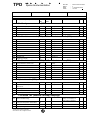
4.2
1.
Calibration Step-description
Nominal
Actual
Value
Value
Reference
Remarks
preparations
Arrival of GOME2 EGSE and other
OK
equipment
2.
Unpack EGSE and other equipment
OK
3.
Incoming inspection
OK
4.
Install EGSE and other equipment
OK
[AD1]
(CTB/DAPB/Pump/Cooler)
5.
Install sub-network to interconnect all
OK
EGSE systems
6.
Install router
OK
7.
Connect OAC to EGSE-sub network
OK
8.
Check network performance
OK
9.
Arrival of Gome2 FM1
OK
10.
Unpack GOME2
OK
11.
Inspect GOME2
OK
12.
Acceptance review
OK
Log IP adresses
[AD1]
Document in acceptance
report
4.3
Ambient block 1
13.
Install GOME2 on AETA MGSE
OK
[AD1]
14.
Mechanical alignment of AETA MGSE
OK
[AD5]
15.
Connect GOME2 to CTB
OK
[AD1]
16.
Connect FPA vacuum pump
OK
[AD1]
17.
Connect Radiant Cooler
OK
[AD1]
18.
Switch on GOME2
OK
Section 3.5
19.
Set detector temperature at TD1 and
OK
Section 3.6
[AD5]
stabilise
20.
Install LRS in front of GOME2, nadir
OK
21.
Set-up LRS in White Light Mode
OK
22.
Optical alignment of LRS with respect
OK
[AD5]
to GOME2 entrance slit
23.
MONITOR.TAL
OK
Section 3.7
24.
AETA.TAL with QTH
OK
Section 3.7
25.
AETA.TAL with Xe
OK
Section 3.7
26.
MONITOR.TAL
OK
Section 3.7
27.
Decision to proceed
OK
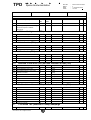
4.4
Ambient block 2
28.
Shut down GOME2
OK
Section 3.5
29.
Install GOME2 on AIRR MGSE
OK
[AD1]
30.
Mechanical alignment of AIRR MGSE
OK
[AD5]
This document contains proprietary
information of TNO. All rights reserved.
PMD cooling must be OFF!
P
N
TPD
DOC.NO.
ISSUE
DATE
PAGE
Space Instrumentation
Date:
Location:
Operator:
:
:
:
:
MO-PR-TPD-GO-0027
4
11 November 2002
16 of 25
PA:
FM identification:
No.
Calibration Step-description
Nominal
Actual
Value
Value
Reference
31.
Connect GOME2 to CTB
OK
[AD1]
32.
Connect FPA vacuum pump
OK
[AD1]
33.
Connect Radiant Cooler
OK
[AD1]
34.
Switch on GOME2
OK
Section 3.5
35.
Set detector temperature at TD1 and
OK
Section 3.6
stabilise
36.
Install Sun Simulator in front of GOME2 OK
[AD5]
37.
Mechanical alignment of Sun Simulator
OK
[AD5]
38.
Optical alignment Sun Simulator with
OK
[AD5]
OK
Section 3.7
Section 3.7
respect to GOME2 sun port
39.
AIRR.TAL
40.
MONITOR.TAL
OK
41.
Decision to proceed
OK
4.5
Install GOME2 in TVC
42.
Shut down GOME2
OK
Section 3.5
43.
Remove GOME2 from MGSE
OK
[AD1]
44.
Install GOME2 on TVC MGSE
OK
[AD1]
45.
Install Gome2 in TVC
OK
[AD1]
46.
Mechanical alignment of MGSE
OK
[AD5]
47.
Connect GOME2
OK
[AD1]
48.
Connect FPA vacuum pump
OK
[AD1]
49.
Connect Radiant Cooler
OK
[AD1]
50.
Switch on GOME2
OK
Section 3.5
51.
Install LRS at Nadir window
OK
[AD5]
52.
Close TVC door
OK
[AD1]
53.
Check warning/alarm system
OK
[AD4]
54.
Optical pre-alignment of LRS with
OK
[AD5]
respect to GOME2 entrance slit
55.
56.
Switch Gome2 off
Gome2 to vacuum
OK
Section 3.5
-5
<10
[AD8]
mbar
57.
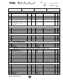
4.6
Start of Bake-out
30°C
[AD8]
TVC/Gome TB2 (nominal temp) campaign
58.
Start Cool down to TB2
59.
Switch on GOME2 when temperature
[AD8]
<303K
Section 3.5
OK
[AD5]
has decreased below 303 K
60.
4.6.1
LRS mechanical alignment
Gome
61.
Set detector temperature to TD2
OK
Section 3.6
62.
Set PMD temperature to ground line
OK
Section 3.6
This document contains proprietary
information of TNO. All rights reserved.
Remarks
PMD cooling must be OFF!
P
N
TPD
DOC.NO.
ISSUE
DATE
PAGE
Space Instrumentation
Date:
Location:
Operator:
:
:
:
:
MO-PR-TPD-GO-0027
4
11 November 2002
17 of 25
PA:
FM identification:
No.
Calibration Step-description
Nominal
Actual
Value
Value
Remarks
Section 3.7
After stabilisation
63.
LINEARITY.TAL
64.
MONITOR.TAL
OK
Section 3.7
65.
Set detector temperature to TD1
OK
Section 3.6
66.
Set PMD temperature to flight line
OK
Section 3.6
67.
LINEARITY.TAL
OK
Section 3.7
68.
MONITOR.TAL
OK
Section 3.7
69.
DIFFUSERMON.TAL
OK
Section 3.7
Diffuser monitoring
4.6.2
OK
Reference
LRS in White light mode
70.
BREWSTERSCAN.TAL with QTH
OK
Section 3.7
Includes ETA/ZETA
71.
BREWSTERSCAN.TAL with Xe
OK
Section 3.7
Includes ETA/ZETA
72.
MONITOR.TAL
OK
Section 3.7
4.6.3
LRS in filter mode (TB2)
73.
Set-up LRS in filter mode
OK
74.
FILTER.TAL with Xe
OK
Section 3.7
75.
FILTER.TAL with QTH
OK
Section 3.7
Dispersion and cross
dispersion
Dispersion and cross
dispersion
76.
4.6.4
MONITOR.TAL
OK
Section 3.7
LRS in slit mode (TB2)
77.
Set-up LRS in slit mode
OK
78.
IFOV.TAL with Xe
OK
Section 3.7
79.
MONITOR.TAL
OK
Section 3.7
4.6.5
LRS in monochromator mode (TB2)
80.
Set-up LRS in monochromator mode
OK
81.
MONOSCAN.TAL with Xe
OK
Section 3.7
For straylight
82.
MONOSCAN.TAL with QTH
OK
Section 3.7
For straylight
83.
MONITOR.TAL
OK
Section 3.7
84.
Decision to proceed
OK
4.6.6
HCL stimulus (TB2)
85.
Set-up HCL stimulus
OK
86.
HCL.TAL
OK
Section 3.7
For FPA wavelength
calibration
87.
4.6.7
MONITOR.TAL
OK
Section 3.7
ORIEL stimulus (TB2)
88.
Set-up Oriel stimulus
OK
89.
ORIEL.TAL
OK
Section 3.7
For PMD wavelength
calibration
90.
MONITOR.TAL
This document contains proprietary
information of TNO. All rights reserved.
OK
Section 3.7
P
N
TPD
DOC.NO.
ISSUE
DATE
PAGE
Space Instrumentation
Date:
Location:
Operator:
:
:
:
:
MO-PR-TPD-GO-0027
4
11 November 2002
18 of 25
PA:
FM identification:
No.
4.6.8
Calibration Step-description
Nominal
Actual
Value
Value
Reference
Zenith sky measurements (TB2)
91.
Install Zenith Sky set-up
OK
[AD5]
92.
Optical alignment of Zenith Sky set-up
OK
[AD5]
93.
ZENITH.TAL
OK
Section 3.7
94.
MONITOR.TAL
OK
Section 3.7
95.
Decision to proceed
OK
4.6.9
Rad/Irrad in sun mode (TB2) and Sun simulator at nadir (TB2)
96.
Install Rad/Irrad Set-up
OK
[AD5]
97.
Setup Rad/Irrad in Sun mode
OK
[AD5]
98.
Align Rad/Irrad Set-up in Sun mode
OK
[AD5]
99.
Install Sun Simulator
OK
[AD5]
100.
Set-up Sun Simulator at Nadir window
OK
[AD5]
101.
Align Sun Simulator
OK
[AD5]
102.
FELRAD.TAL
OK
Section 3.7
103.
MONITOR.TAL
OK
Section 3.7
104.
SUNRAD.TAL
OK
Section 3.7
105.
Decision to proceed
OK
4.6.10
Rad/Irrad in nadir mode (TB2) and Sun simulator at sun (TB2)
106.
Set-up Rad/Irrad in Nadir mode
OK
[AD5]
107.
Align Rad/Irrad Set-up in Nadir mode
OK
[AD5]
108.
Set-up Sun Simulator at Sun window
OK
[AD5]
109.
Align Sun Simulator
OK
[AD5]
110.
FELIRR.TAL
OK
Section 3.7
111.
MONITOR.TAL
OK
Section 3.7
112.
SUNIRR.TAL
OK
Section 3.7
113.
Decision to proceed
OK
4.6.11
Remarks
Sphere in nadir (TB2)
114.
Install TVSPH in front of Nadir window
115.
Align TVSPH with respect to GOME2
[AD5]
OK
[AD5]
entrance slit
116.
SPHERE_TAL
OK
Section 3.7
117.
MONITOR.TAL
OK
Section 3.7
118.
Decision to proceed
OK
4.7
Including SLS over diffuser
TVC/Gome TB1 (nominal-10 temp) campaign
119.
Switch off PMD cooling
OK
During –10 campaign no
120.
Change TB temperature and stabilise
OK
121.
Install LRS
OK
[AD5]
122.
Optical pre-alignment of LRS with
OK
[AD5]
PMD cooling is allowed!
This document contains proprietary
information of TNO. All rights reserved.
P
N
TPD
DOC.NO.
ISSUE
DATE
PAGE
Space Instrumentation
Date:
Location:
Operator:
:
:
:
:
MO-PR-TPD-GO-0027
4
11 November 2002
19 of 25
PA:
FM identification:
No.
Calibration Step-description
Nominal
Actual
Value
Value
Reference
Remarks
respect to GOME2 entrance slit
123.
Optical alignment (check + fine-tuning)
OK
[AD5]
of LRS with respect to GOME2
entrance slit
4.7.1
LRS in white light mode (TB1)
124.
Set-up LRS in White light mode
OK
125.
BREWSTERSCAN.TAL with QTH
OK
Section 3.7
126.
BREWSTERSCAN.TAL with Xe
OK
Section 3.7
127.
MONITOR.TAL
OK
Section 3.7
4.7.2
Oriel stimulus (TB1)
128.
Set-up Oriel Monochromator
OK
129.
ORIEL.TAL
OK
Section 3.7
130.
MONITOR.TAL
OK
Section 3.7
4.7.3
HCL stimulus (TB1)
131.
Set-up HCL stimulus
OK
132.
HCL.TAL
OK
Section 3.7
133.
MONITOR.TAL
OK
Section 3.7
134.
Decision to proceed
OK
4.7.4
Rad/Irrad in sun mode (TB1) and Sun simulator at nadir (TB1)
135.
Install Rad/Irrad Set-up
OK
[AD5]
136.
Set-up Rad/Irrad in Sun mode
OK
[AD5]
137.
Align Rad/Irrad Set-up in Sun mode
OK
[AD5]
138.
Install Sun Simulator
OK
[AD5]
139.
Set-up Sun Simulator at Nadir window
OK
[AD5]
140.
Align Sun Simulator
OK
[AD5]
141.
FEL_ABS.TAL
OK
Section 3.7
142.
MONITOR.TAL
OK
Section 3.7
143.
SUSI.TAL
OK
Section 3.7
4.7.5
Rad/Irrad in nadir mode (TB1) and Sun simulator at sun (TB1)
144.
Set-up Rad/Irrad in Nadir mode
OK
[AD5]
145.
Align Rad/Irrad Setup in Nadir mode
OK
[AD5]
146.
Set-up Sun Simulator at Sun window
OK
[AD5]
147.
Align Sun Simulator
OK
[AD5]
148.
FEL_ABS.TAL
OK
Section 3.7
149.
MONITOR.TAL
OK
Section 3.7
150.
SUSI.TAL
OK
Section 3.7
151.
Decision to proceed
OK
4.8
152.
Eta/Zeta only
TVC/Gome TB3 (nominal+10 temp) campaign
Change TB temperature and stabilise
This document contains proprietary
information of TNO. All rights reserved.
OK
P
N
TPD
DOC.NO.
ISSUE
DATE
PAGE
Space Instrumentation
Date:
Location:
Operator:
:
:
:
:
MO-PR-TPD-GO-0027
4
11 November 2002
20 of 25
PA:
FM identification:
No.
Calibration Step-description
Nominal
Actual
Value
Value
Reference
153.
Switch on PMD cooling
154.
Install LRS
OK
[AD5]
155.
Optical pre-alignment of LRS with
OK
[AD5]
OK
[AD5]
Remarks
OK
respect to GOME2 entrance slit
156.
Optical alignment (check + fine-tuning)
of LRS with respect to GOME2
entrance slit
4.8.1
LRS in white light mode (TB1)
157.
Set-up LRS in White light mode
OK
158.
BREWSTERSCAN.TAL with QTH
OK
Section 3.7
159.
BREWSTERSCAN.TAL with Xe
OK
Section 3.7
160.
MONITOR.TAL
OK
Section 3.7
4.8.2
HCL stimulus
161.
Set-up HCL stimulus (TB3)
OK
162.
HCL.TAL
OK
Section 3.7
163.
MONITOR.TAL
OK
Section 3.7
164.
Decision to proceed
OK
4.8.3
Oriel stimulus (TB3)
165.
Set-up oriel Monochromator
OK
166.
ORIEL.TAL
OK
Section 3.7
167.
MONITOR.TAL
OK
Section 3.7
4.8.4
Rad/Irrad in sun mode (TB3) and Sun simulator at nadir (TB3)
168.
Install Rad/Irrad Set-up
OK
[AD5]
169.
Set-up Rad/Irrad in Sun mode
OK
[AD5]
170.
Align Rad/Irrad Set-up in Sun mode
OK
[AD5]
171.
Install Sun Simulator
OK
[AD5]
172.
Set-up Sun Simulator at Nadir window
OK
[AD5]
173.
Align Sun Simulator
OK
[AD5]
174.
FELRAD.TAL
OK
Section 3.7
175.
MONITOR.TAL
OK
Section 3.7
176.
SUNRAD.TAL
OK
Section 3.7
4.8.5
Eta/Zeta only
Rad/Irrad in nadir mode (TB3) and Sun simulator at sun (TB3)
177.
Set-up Rad/Irrad in Nadir mode
OK
[AD5]
178.
Align Rad/Irrad Setup in Nadir mode
OK
[AD5]
179.
Set-up Sun Simulator at Sun window
OK
[AD5]
180.
Align Sun Simulator
OK
[AD5]
181.
FELIRR.TAL
OK
Section 3.7
182.
MONITOR.TAL
OK
Section 3.7
183.
SUNIRRTAL
OK
Section 3.7
This document contains proprietary
information of TNO. All rights reserved.
P
N
TPD
DOC.NO.
ISSUE
DATE
PAGE
Space Instrumentation
Date:
Location:
Operator:
:
:
:
:
MO-PR-TPD-GO-0027
4
11 November 2002
21 of 25
PA:
FM identification:
No.
184.
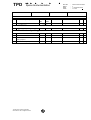
4.9
185.
4.10
Calibration Step-description
Decision to proceed
Nominal
Actual
Value
Value
Reference
OK
CATGAS measurements at TB2
CATGAS measurements
Procedure TBW
Post test and packing
186.
Perform functional test
OK
187.
Shut down GOME2
OK
Section 3.5
188.
Pack GOME2 instrument EGSE and
OK
[AD1]
other equipment
189.
Remarks
Post Test Review (PTR)
This document contains proprietary
information of TNO. All rights reserved.
OK
P
N
TPD
Space Instrumentation
DOC.NO.
ISSUE
DATE
PAGE
:
:
:
:
MO-PR-TPD-GO-0027
4
11 November 2002
22 of 25
4.11 Non-conformance Reporting
In failure cases, non-conformance reporting shall follow prescriptions of the Product
Assurance Plan.
4.12 Deviations from the Procedure
Deviations are acceptable as long as test purposes and objectives remain valid. In
any case deviations need to be introduced via the “Procedure Variation Sheet”. A
form sheet is provided in section 6.
Where a non-conformance was the reason for a procedure deviation, a nonconformance report needs to be generated separately.
This document contains proprietary
information of TNO. All rights reserved.
TPD
5.
Space Instrumentation
DOC.NO.
ISSUE
DATE
PAGE
:
:
:
:
MO-PR-TPD-GO-0027
4
11 November 2002
23 of 25
Procedure sign-off sheet
The identified test article has been successfully calibrated in accordance with this
procedure and all open items and non-conformance reports are closed except those
listed here below:
Date and signatures of:
Test Manager:
Product Assurance:
Customer:
This document contains proprietary
information of TNO. All rights reserved.
TPD
6.
Space Instrumentation
:
:
:
:
MO-PR-TPD-GO-0027
4
11 November 2002
24 of 25
Procedure Variation Sheet
TNO-TPD
Cal
Step
No.
DOC.NO.
ISSUE
DATE
PAGE
Project: Gome-2 Instrument Calibration
Test Step description
Date:
This document contains proprietary information of TNO-TPD.
All rights reserved.
Procedure Variation Sheet
Nominal Value Actual Value
P
N
Operator: PA:
Test
Location:
Customer:
Procedure No.
Date
Issue:
Sheet
PVS No.
Remarks
TPD
7.
Space Instrumentation
DOC.NO.
ISSUE
DATE
PAGE
:
:
:
:
MO-PR-TPD-GO-0027
4
11 November 2002
25 of 25
Gome 2 NCR's affecting Calibration Execution (GAL info)
This information shall be obtained from GAL
This document contains proprietary information of TNO-TPD.
All rights reserved.