1
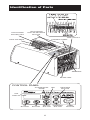
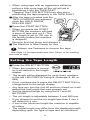
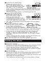
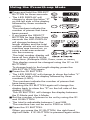
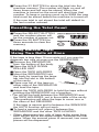
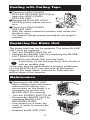
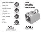
EZ-7000
Industrial Duty
Tape Dispenser
Instruction
Manual
Read This Before Use
Thank you for buying our EZ-7000 tape dispenser.
EZ-7000 is a very compact, high powered unit which
can cut and dispense many kinds of tape including
non-adhesive products.
Please read this instruction manual carefully.
For your safety, please keep this manual for reference,
retraining and trouble shooting.
Contents
Read This Before Use . . . . . . . . . . . . . . . . . . . . . . . . 2
Safety Instructions . . . . . . . . . . . . . . . . . . . . . . . . . . . 3
Definition of Warning and Caution Symbols. . . . . . . 3-5
Identification of Parts . . . . . . . . . . . . . . . . . . . . . . . . 6-7
Loading the Tape . . . . . . . . . . . . . . . . . . . . . . . . . . . . 8
Setting the Tape Length . . . . . . . . . . . . . . . . . . . . . . . 9
Setting the Mode . . . . . . . . . . . . . . . . . . . . . . . . . 10-13
Memory Function . . . . . . . . . . . . . . . . . . . . . . . . . . . 13
Resetting the Total Count . . . . . . . . . . . . . . . . . . . . . 14
Using Narrow Tape/Using Two Rolls at Once . . . . . . 14
Dealing with Curling Tape . . . . . . . . . . . . . . . . . . . . . 15
Replacing the Blade Unit . . . . . . . . . . . . . . . . . . . . . 15
Maintenance . . . . . . . . . . . . . . . . . . . . . . . . . . . . 15-16
Error Messages. . . . . . . . . . . . . . . . . . . . . . . . . . 16-17
Trouble Shooting. . . . . . . . . . . . . . . . . . . . . . . . . . . . 18
Specifications . . . . . . . . . . . . . . . . . . . . . . . . . . . . . . 19
2
Safety Instructions
The safety guidelines in this Instruction Manual must
be observed in order to prevent damage to the
machine or injury to the operator or other persons.
The safety guidelines designated "Warning " and
"Caution" describe possible injury or damage that may
be suffered from operating or maintaining the machine
in a manner other than as described in this Instruction
Manual.
Read and follow the safety precautions carefully before
reading the Instruction Manual.
Definition of Warning
and Caution Symbols
Indicates a potentially hazardous situation; which could
result in death or serious injury.
Indicates that mishandling may result in danger and
that the operator is at risk of injury, or the machine is at
risk of damage.
Indicates Caution; A symbol within the triangle, or the
description, will indicate a specific hazard.
A Prohibited Action; A symbol within the circle, or the
description, will indicate prohibited action.
A Required Action; A symbol within the circle, or the
description, will indicate a required action.
3
Do not operate the machine with wet hands.
Do not plug in or unplug the cord with wet
hands. Failure to observe this may result in
injury due to electric shock.
Never insert your finger, or any other body
part, or any foreign object into the machine.
Failure to observe this may result in injury.
Keep hair or loose clothing away from the
machine while it is operating. Failure to
observe this may result in injury.
This machine is intended for industrial use
only. Do not allow untrained operators or
children to operate the machine. Failure to
observe this may result in injury.
Turn off the power switch and unplug the
machine prior to replacing the blade unit or
performing any maintenance on the
machine. Failure to observe this may result in
serious injury.
Do not use this machine for anything other
than its specified applications. Use of the
machine for any unintended applications can
cause injury to the operator or failure of the
machine.
4
Do not expose the machine to water or other
liquids. Do not install or use the machine where
it may come into contact with water or other
liquids. Exposure to water or other liquid can
cause injury due to electric shock, or failure of
the machine.
Never modify or disassemble the machine.
This can cause injury or failure of the machine.
Always unplug, or plug the machine in, by
holding the plug. Never pull on the cord.
Pulling on the cord can result in an injury from
electric shock.
Never place foreign objects into the
machine. This can cause failure of the
machine.
An operator’s presence is required
whenever the machine is in operation. Turn
the machine off and unplug the cord when the
operator is not present. Failure to observe this
can result in injury.
Do not cut or damage the power cord. A cut
or damaged cord can lead to electric shock, a
short circuit or possible fire hazard.
Make sure the cord is connected properly to
the electrical outlet as well as the receptacle
on the back of the machine. A loose
connection can result in high heat or fire.
Do not use the machine in areas where
moisture is present, high temperatures exist
or a high content of dust or dirt is present.
This can result in failure of the machine.
Always install and operate the machine on a
flat, stable surface. Dropping the machine can
lead to failure of the machine or injury to the
operator.
Always remove the tape from the machine
when you are finished with the operation.
Leaving the tape in the machine may lead to a
buildup of adhesive on the parts, or cause the
tape to curl.
5
Identification of Parts
HOLD DOWN
ROLLER UNIT
HOLD DOWN
ROLLER RELEASE
BUTTON
TAPE OUTLET
CONTROL PANEL
TAPE HOLDERS
SENSORS
BLADE UNIT
CONTROL PANEL
AUTO/MANUAL
MODE
LED
REVERSE
BUTTON
LED
DISPLAY
S1
BUTTON
S2
BUTTON
SELECT
BUTTON
6
FORWARD
BUTTON
START
BUTTON
TAPE FEED
ROLLER
TAPE INLET
ROLLER LOCK
LEVER
TAPE
HOLDERS
AC CORD
INLET
TWEEZERS
SPARE
FUSE
TAPE HOLDER
ADJUST LEVER
LOWER
HOLDER
POWER
SWITCH
FUSE
FUSE
HOLDER
BOTTOM OF BODY
BLADE UNIT
RELEASE LEVER
SEPARATOR
7
Loading the Tape
(see page 14 for tape less than 15 mm wide)
■ Plug in the AC CORD to the
AC CORD inlet.
■ Make sure the POWER
SWITCH is off then plug into a
properly grounded AC outlet.
■ Turn the POWER SWITCH on.
• When the POWER SWITCH
is turned on the red LED
DISPLAY will indicate the
last length programmed.
• When the POWER SWITCH is turned on the
mode will be set to Manual.
■ Press the HOLD DOWN
ROLLER RELEASE BUTTON.
■ Place a roll of tape in the
machine.
■ Hold the tape by adjusting the
TAPE HOLDERS.
• Adjust the TAPE HOLDERS
to the proper width by sliding
the TAPE HOLDER ADJUST
LEVER to the front of the machine, to open, or to the
rear of the machine, to close. The TAPE HOLDERS
should lightly hold the roll in the center of the cavity
in the machine. This is very important because it
keeps the tape centered as it passes over the
Sensor in front of the BLADE UNIT.
• Pull the LOWER HOLDER out to support a large
roll of tape.
■ Fold the edge of the tape over
approximately 20 mm and
insert into the TAPE INLET.
■ Press the FWD BUTTON until
the tape comes out of the
TAPE OUTLET.
• If the buzzer sounds and the
LED DISPLAY indicates an
error press the REV BUTTON
to remove the tape and start over.
• Pressing the REV BUTTON runs the motor in
reverse just long enough to remove the tape from
the blade.
• If the length of the tape is longer it may be
necessary to press the REV BUTTON a second or
third time to remove the tape from the machine.
8
• When using tape with an aggressive adhesive
pulling a little more tape off the roll will aid in
positioning it into the TAPE INLET.
• "Tapping" the FWD BUTTON may also aid in
positioning the tape properly in the TAPE INLET.
■ After the tape is loaded and the
TAPE HOLDERS are adjusted
close the HOLD DOWN
ROLLER UNIT.
■ Press the START BUTTON.
• When you press the START
BUTTON the machine will feed
a piece of tape and cut it. (The
tape length is set to 100 mm at
the factory before the machine
is shipped.)
• Remove that first piece and discard it.
■ The Machine is Now Ready for Use
Always use Tweezers to remove the tape.
* See Page 14 for tape width less than 15mm or for loading
two rolls of tape.
Setting the Tape Length
■ Press the SELECT BUTTON
• When the machine is turned
on it will default to the length
display.
• The length will be displayed by up to three numbers
in the red LED DISPLAY being lit. (Example 8, 88, or
888)
• If four numbers are lit press the SELECT BUTTON to
change back to the length display.
• Any time you turn the unit off and turn it back on it will
default the last length that was properly set.
• Set the desired length by using the S1 and S2
BUTTONS.
• The cut length is adjustable between 4 and 999 mm.
• If you attempt to set the cut length less than 4 mm it
will default to 4 mm.
• 4 mm is the minimum length the machine is capable
of cutting.
• The actual length may differ from the displayed length
depending upon the type of tape and its conditions.
9
■ Press the S1 BUTTON
• When you press the S1
BUTTON, three digits will
light and the right hand digit
will flash. If S1 is pressed
again within three seconds the middle digit will flash.
If S1 is pressed again within three seconds the left
digit will flash.
To change a digit while it is flashing press S2.
■ Press the S2 BUTTON
• When you press the S2
BUTTON while a digit is
flashing that digit will
increase from 0 to 9. If you
continue to press S2 you will
start over with that same digit.
• You can not change to the next digit until you press
S1 again.
■ The LED DISPLAY stops
flashing after three seconds.
• If you have not finished
setting the length and pause
for three seconds the LED DISPLAY will stop flashing.
The number shown on the display is the set length.
• If the actual cut length differs from the displayed
length, it may be due to the type of tape and its
condition. Set the LED DISPLAY to a longer length
and retry.
• When cutting shorter lengths of tape the length may
not be consistent or the tape may jam.
■ Try several test cuts to insure proper operation.
Setting the Mode
■ MANUAL MODE
• Press the START BUTTON once, the machine feeds
one piece of tape to desired length and cuts it.
• To cut another piece, press the START BUTTON
again. The machine will feed and cut a piece of tape
each time the button is pressed.
■ AUTO MODE
• Press the START BUTTON once, the machine feeds
one piece of tape to the desired length and cut it.
• When that piece of tape is removed the machine will
feed and cut another piece.
• The machine will feed and cut a new piece of tape
10
each time a piece is removed from the machine.
■ P-Mode (Preset Mode)
• You can program the machine to alert you after a
desired number of pieces of tape have been cut (up
to 999 pieces).
• A buzzer will sound when the programmed total has
been reached, and the machine will not
automatically feed another piece.
• You must press the START BUTTON again to start
the machine and restart the programmed count.
The buzzer will sound both in AUTO or MANUAL
MODE.
■ L-Mode (Loop Mode)
• When cutting non-adhesive material you can preset
the number of pieces to be cut (up to 999 pieces).
• The machine will cut the specified number of pieces
and stop.
• A buzzer will sound when the preset total has been
reached, and machine will stop cutting.
• You must press the START BUTTON to start the
machine again.
Changing between
AUTO/MANUAL MODE
■ Press AUTO/MANUAL
MODE BUTTON
• Each time you press the
AUTO/MANUAL MODE
BUTTON the mode will
change between AUTO and
MANUAL.
• When you select MANUAL,
the green LED above the button will not be lit.
• When you select AUTO, the green LED will flash until
the START BUTTON is pressed. After the START
BUTTON has been pressed and a piece of tape has
been fed and cut, the green LED will remain lit.
• If the green LED remains flashing the SENSORS
have not detected the tape. The START BUTTON will
have to be pressed to dispense another piece of tape.
This can occur if the tape is too narrow, or the
adhesive is too light to allow the tape to stick in the
TAPE OUTLET. If the tape will not stick, the machine
can not be used in the AUTO MODE.
You will have to press the START BUTTON each
time you want a piece of tape.
11
Using the Preset/Loop Mode
■ Press and hold the SELECT
BUTTON for three seconds.
• The LED DISPLAY will
change to show the letter "P"
on the left side of the display
followed by three numbers
(P000).
The numbers indicate the
number of pieces that have
been preset.
• If you press the SELECT
BUTTON for less than three
seconds the LED DISPLAY
will change between the
length display and the total
number pieces cut since the
machine was turned on, or
since a total was entered
into the memory.
The total number display will
have all four digits lit at the
same time. (Example 0008, 0088, 0880 or 8888)
This display cannot be changed using the S1 or S2
BUTTONS.
To change back to the length display, press the
SELECT BUTTON again.
■ Press the S2 BUTTON.
• The LED DISPLAY will change to show the letter "L"
on the left side of the display followed by three
numbers (L000).
The numbers indicate the number of pieces that
have been preset.
• Pressing the S2 BUTTON again will change the
display back to show the "P" on the left side of the
display. (P000).
The S2 BUTTON will change the display between
the P-Mode and the L-Mode.
■ Set the number of pieces to be cut by using the S1
and S2 BUTTON.
• The total is adjustable between 1 and 999.
The machine can not be set to P000 or L000.
■ Press the S1 BUTTON.
When you press the S1 BUTTON, the right hand
digit will flash. If S1 BUTTON is pressed again within
12
three seconds the middle
digit will flash. If S1 BUTTON
is pressed again within three
seconds the left digit will
flash. To change the digit
while it is flashing press S2
BUTTON.
■ Press the S2 BUTTON
When you press the S2
BUTTON while a digit is
flashing that digit will
increase from 0 to 9. If you continue to press S2
BUTTON you will start over with that same digit.
You can not change to the next digit until you press
S1 BUTTON again.
■ The LED DISPLAY stops flashing after three
seconds.
• If you have not finished setting the number and
pause for three seconds the display will stop
flashing.
The number showing on the display will be the
number to cut unless you have attempted to set 000.
If you attempt to set the total to 000 the digit you
selected will continue to flash until you change it to
something other than 0.
■ To stop the machine while it is running in L-Mode
press the START BUTTON.
• To restart press the START BUTTON a second time.
■ To operate the machine in
P-Mode or L-Mode you
must have the "P" or "L"
showing on the display.
• The number programmed
will remain when the unit is
turned off and turned back on.
Memory Function
The machine memory will keep track of the number of
pieces cut since it was turned on, up to 9999 pieces.
This number will be reset to 0000 when the machine is
turned off and turned back on unless a number has
been stored in memory.
■ Press the SELECT BUTTON and release
before three seconds pass. The number
shown will be the number of pieces cut
since the machine was turned on.
13
■ Press the S1 BUTTON to store the total into the
machine memory. The number will flash on and off
three times and will now be stored. When the
machine is turned on the count will start from that
number. To keep a running count up to 9999 the new
total must be stored before the machine is turned off.
If the new total is not stored the total will default to
the last number entered.
Resetting the Total Count
■ Press the SELECT BUTTON
and the number shown will
be the number of pieces cut.
■ Press the S2 BUTTON for
three seconds to clear the
memory.
Using Narrow Tape/
Using Two Rolls at Once
If the tape is less than 15 mm wide or if you want to
dispense two rolls at once use the SEPARATOR.
■ Remove the SEPARATOR
from the bottom of the body.
■ Open the HOLD DOWN
ROLLER UNIT.
■ Open the TAPE HOLDERS.
■ Insert the SEPARATOR into
the body by inserting the large
tab into the slot in the bottom
of the cavity.
■ Place one roll of the tape on
either side of the SEPARATOR
and load the tape.
■ Adjust the TAPE HOLDERS to hold the tape without
pushing the SEPARATOR out of position.
• The roll will be held between the SEPARATOR and
the TAPE HOLDERS, not in the middle of the cavity.
This positioning will allow the tape to cover one or
the other of the SENSORS.
If the tape is narrow and in between the SENSORS
the AUTO function will not work.
■ To load a second roll, place it between the
SEPARATOR and the other TAPE HOLDER.
• When dispensing two rolls of tape at the same time
both will be fed to the same length. Remove the first
piece. When the second piece is removed, two more
pieces will be dispensed.
14
Dealing with Curling Tape
■ Press the HOLD DOWN
ROLLER RELEASE BUTTON to
open the HOLD DOWN
ROLLER UNIT.
■ Spread the ROLLER LOCK
LEVER so that rollers can not
turn.
■ Close the HOLD DOWN
ROLLER UNIT.
• With the rollers locked the tension may cause the
length to vary.
Cut several sample pieces and adjust the length if
needed.
Replacing the Blade Unit
The blade itself can not be replaced. The whole BLADE
UNIT must be replaced.
• Turn the POWER SWITCH off.
• Remove the BLADE UNIT by releasing the BLADE
UNIT RELEASE LEVER.
• Install the new Blade Unit onto the body.
Push down on the housing firmly until it locks in
with an audible click.
To be sure that the lower blade is properly positioned,
turn the BLADE UNIT over and look at the bottom
edge of the lower blade. It should be flush with the
bottom edge of the opening.
Maintenance
■ Cleaning the BLADE UNIT
When cutting tapes with heavy
adhesive the residue can
accumulate on the blade. It is
necessary to remove the
BLADE UNIT for cleaning.
• Turn the POWER SWITCH off.
• Remove the BLADE UNIT by
releasing BLADE UNIT
RELEASE LEVER.
• Use alcohol on a clean dry
cloth, or swab to remove the
residue.
• Replace the BLADE UNIT.
15
■ Lubricating the Blade
Lubricate the Blade to prevent
tape residue from the sticking
to the blade.
• Turn the POWER SWITCH off.
• Remove the BLADE UNIT from
the body.
• Locate the three oil holes on
the back side of the top blade.
• Squeeze one drop of blade oil into each hole.
• Do not over lubricate.
• Wipe excess oil away with a cotton cloth.
• Replace the BLADE UNIT onto the body.
• Turn the POWER SWITCH on.
Make several test cuts to be sure the tape does not
fall off the TAPE OUTLET.
USE CAUTION IN
■ Cleaning the Sensors
HANDLING SENSORS
There are two SENSORS below
the TAPE OUTLET. If the openings
are covered with tape, residue or
debris, the SENSORS will not
detect the presence of the tape.
• Always clean around the
SENSORS.
• With the BLADE UNIT removed carefully clean the
openings to prevent damage to the SENSORS.
■ Cleaning the Body
Clean the body with a damp cloth using mild detergent.
Never use alcohol or solvents on plastic parts.
Whenever you clean or replace the BLADE
UNIT do not touch the cutting edge of the blade.
Error Messages
The buzzer will sound and a message will flash on the
LED DISPLAY to indicate an error.
■ E-1 Tape Jam
Indicates the tape is jammed.
REMOVE THE TAPE
• Press the REV BUTTON so that
the tape can be pulled back and
CHECK THE INSIDE OF
removed.
THE TAPE OUTLET
REMOVE THE TAPE WASTE
• Check the TAPE OUTLET for
pieces of tape or glue residue and
CLEAR THE MESSAGE
remove with TWEEZERS.
• Press the START BUTTON to
SET THE TAPE
clear the error message.
• Load the tape again as prescribed.
16
■ E-2 Blade out of Position
Indicates the blade is not installed
TURN POWER OFF
properly or has stopped due to the
REMOVE BLADE UNIT
thickness or hardness of the tape.
• Turn the POWER SWITCH off.
TURN POWER SWITCH ON
• Remove the BLADE UNIT by
FEED THE TAPE
releasing the BLADE UNIT
RELEASE LEVER and lifting the
CUT TAPE BETWEEN BLADE
assembly out of the body.
UNIT AND OUTLET ROLLER
• Turn the POWER SWITCH on.
REMOVE THE TAPE
• Press the FWD BUTTON and
feed the tape once, cut the tape
CLEAN BLADE UNIT
INSTALL THE UNIT
between the TAPE OUTLET and
the location of the BLADE UNIT
CLEAN BLADE UNIT
with scissors.
INSTALL THE UNIT
• Press the REV BUTTON to
CLEAR THE MESSAGE
remove the tape.
• Turn the POWER SWITCH off.
SET THE TAPE
• Clean the BLADE UNIT and
replace it.
• Turn the POWER SWITCH on.
• Press the START BUTTON to
clear the error message.
REMOVE THE TAPE
■ E-3 Motor Stopped
CHECK THE INSIDE OF THE
Indicates the motor has stopped due TAPE OUTLET
REMOVE THE TAPE WASTE
to an overload.
• Press the REV BUTTON to
CLEAR THE MESSAGE
remove the tape.
• Turn the POWER SWITCH off.
SET THE TAPE
• Check the BLADE UNIT and
TAPE OUTLET carefully.
• Clear away the tape waste or glue residue with the
TWEEZERS.
• Turn the POWER SWITCH on.
• Press the START BUTTON to clear the error
message.
When correcting an error, never touch the
BLADE with the POWER SWITCH on.
If the machine does not work normally after
correcting an error, turn off the POWER
SWITCH and stop using the machine.
Do not use tape generating static electricity over
1000V. It may cause failure of the machine.
Before returning the machine for repairs, check the
following items.
17
Troubleshooting
■ The POWER SWITCH is on but the machine does
not run.
• The AC cord is loose.
Be sure the cord is plugged into the outlet firmly.
• The FUSE is blown.
Replace the FUSE.
If the FUSE is blown again after replacing it, stop
using the machine immediately.
■ After removing a piece of tape, the next piece does
not feed when in the AUTO mode.
• The mode is set to MANUAL.
Set the mode to AUTO.
• There is debris covering the SENSORS.
Remove the debris.
• The tape does not go over the SENSORS.
Use SEPARATOR for narrow tape less than 15 mm.
• There is bright light very close to the SENSORS.
Do not shine bright light at or near the SENSORS.
• The tape has extremely low reflectance
Some types of tape may not be used in AUTO
mode.
■ The BLADE does not move smoothly.
• The BLADE UNIT is not in the proper position.
Check the BLADE UNIT and push down on the
housing firmly until it locks in with an audible click.
■ The length of the tape is different from the setting
length.
• Tape has aggressive adhesive.
Correct the setting after cutting several test pieces.
• Tape is very elastic
■ Tape curls excessively.
• The machine is not grounded.
Check ground on cord.
• The ROLLER LOCK is disengaged.
Engage the ROLLER LOCK.
• ANTI-STATIC BRUSH is worn out.
Replace the ANTI-STATIC BRUSH.
If the machine still does not work properly, stop
using the machine immediately and contact ASG
for repair authorization.
■ Spare parts are available from ASG
18
Specifications
Power Requirement: 120V 50Hz/60Hz ( 220V- 240V
units available)
Input Voltage Range: ±5%
Wattage: 25W
Dimensions: 115(w) x 140(h) x 215 (d) mm
Weight: 2.8 kg.
Body Material: Anti-Static ABS
Tape Length: 4-999 mm
Tape Width: 6-50mm
Feeding Speed: 200mm/sec. (when cutting craft tape)
Max. Outside dia, of Roll: 300 mm
Accessories: Power Cord
2A Fuse (built-in inlet)
Separator
Tweezers
Blade Oil
Note: The specifications are subject to change without
prior notice.
The length of the tape may differ from the set length
depending upon the type of tape or its condition.
Some types of tape available with the machine may not
be cut depending upon conditions.
19
Products & Services offered by ASG:
• Electric Torque Drivers
• Manual Torque Drivers
• Video Inspection
Equipment
Torque Controlled Drivers
• Process Monitors/Qualifiers
• Torque Testers
• Assembly Robots
• Auto Screw
Feed Systems
Inspection & Testing
• Screw Feeders
• Automatic Tape
Dispensers
• Lead Trimmers
Production Aides
• Assembly
Automation
Components
• Repairs
• Calibration
Automation Products
Division of Jergens, Inc.
15700 South Waterloo Road, Cleveland, Ohio 44110
888/486-6163 • E-Mail: [email protected]
www.asg-jergens.com
10/03
©2003 Jergens Inc.