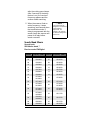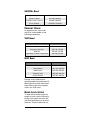
1
www.radioshack.comSM
PRO-96 Digital
Trunking Scanner
Catalog # 20-526
OWNER’S MANUAL —
Please read before using this equipment.
Thank you for
purchasing the
RadioShack PRO-96
Digital Handheld
Scanner. This product
is the first of an
innovative and exciting
new generation of
RadioShack scanning
receivers capable of
receiving Phase 1
APCO-25 C4FM/IMBE
digital voice
modulation from the
newest and most
sophisticated
conventional and
trunked radio
networks.
Your Radio Shack
Digital Handheld
Scanner is ready to
receive digital
conventional and
trunked radio
transmissions. No
additional hardware or
add-on cards are
needed.
!
!
IMPORTANT
If an icon appears at the end of a paragraph, go to the box on that page
with the corresponding icon for pertinent information.
— Warning
— Caution
! — Important
Ó — Hint
Ô — Note
o
TABLE OF CONTENTS
Features ................................................................................... 4
The FCC Wants You to Know ................................................. 10
Scanning Legally ............................................................... 11
Getting Familiar With Your Scanner ....................................... 12
About the Keypad .............................................................. 14
Understanding Your Scanner’s Memory Organization ...... 16
Channel Storage Banks ..................................................... 17
Channels ........................................................................... 18
Search Banks .................................................................... 18
Understanding Your Scanner’s Channel Receive Modes .. 19
Preparation ............................................................................. 24
Listening Safely ................................................................. 24
Traffic Safety ...................................................................... 25
Power Sources .................................................................. 25
Using Batteries .................................................................. 26
Using AC Power ................................................................ 27
Using Vehicle Battery Power ............................................. 28
Antenna ............................................................................. 28
Programming Your Scanner ................................................... 30
Programming Conventional Channels ............................... 30
Programming Trunked Systems ........................................ 32
Programming Motorola Analog, Digital,
and APCO-25 Trunking Systems ....................................... 33
Programming EDACS Trunking Systems .......................... 34
Programming Motorola VHF and UHF Trunking Systems . 34
Programming Motorola 800 MHz Splinter Systems ........... 36
General Programming Notes ............................................. 45
Operating Your Scanner ......................................................... 48
Initial Preparation ............................................................... 48
Searching and Tuning ....................................................... 52
Searching a Preprogrammed Frequency Range ............... 52
Using Zeromatic ................................................................ 59
Using Seek Search ............................................................ 60
Manually Tuning a Frequency ........................................... 61
Using Frequency Copy ........................................................... 61
Copying a Frequency into a Specified Channel ................. 62
Copying a Frequency into a Vacant Channel in a Specified
Bank .................................................................................. 63
Coping a Frequency into the Priority Channel ................... 63
Special Features ..................................................................... 64
Listening to the Weather Band .......................................... 64
Listening to a Weather Channel ........................................ 64
Using the Delay Function .................................................. 66
Locking Out Channels or Frequencies .............................. 67
Changing the Receive mode ............................................. 69
Using the Attenuator .......................................................... 70
Turning the Key Tone On and Off ...................................... 71
2
Using the Display Backlight ................................................ 72
Using the Keylock .............................................................. 74
Changing the Display Contrast ......................................... 74
Working with V-Scanners ................................................... 81
Cloning the Programmed Data .......................................... 82
Trunking Special Features ..................................................... 83
Trunking Operation ........................................................... 83
Activating ID Lockout While Scanning .............................. 89
Trunked Delay Function .................................................... 90
Clearing Talkgroup IDs ...................................................... 91
Digital Operation .......................................................................92
Updating the DSP Firmware ............................................. 94
A General Guide To Frequencies .......................................... 96
Guide To The Action Bands ................................................... 98
Typical Band Usage (in MHz) ........................................... 98
Primary Usage .................................................................. 99
Band Allocation ................................................................. 99
Frequency Conversion ......................................................... 106
Troubleshooting ................................................................... 106
Troubleshooting Chart .................................................... 107
Resetting / Initializing the Scanner .................................. 108
Care ..................................................................................... 109
Service and Repair .............................................................. 109
Specifications ....................................................................... 110
Command Quick Reference Guide ...................................... 113
© 2003 RadioShack Corporation
All Rights Reserved.
RadioShack, RadioShack.com, Hypersearch, Hyperscan, VScanner, and Adaptaplug are trademarks used by RadioShack
Corporation.
Motorola, Smartnet, ASTRO and Privacy Plus are registered
trademarks of Motorola Inc.
EDACS is a registered trademark of MA-COM Inc.
The IMBE™ voice coding Technology embodied in this
product is protected by intellectual property rights
including patent rights, copyrights and trade secrets of
Digital Voice Systems, Inc. This voice coding Technology
is licensed solely for use within this Communications
Equipment. The user of this Technology is explicitly
prohibited from attempting to decompile, reverse
engineer, or disassemble the Object Code, or in any other
way convert the Object Code into a human readable form.
U.S. Pat. Nos. 5,870,405 and 5,517,511.
This device made under license under one or more of the
following U.S. Patents: 4,590,473; 4,636,791; 5,148,482;
5,185,796; 5,271,017; 5,377,229
3
FEATURES
Your Radio Shack Digital
Handheld Scanner features
Intelligent Adaptive Digital
Tracking for optimal reception of
digital signals from a variety of
digital conventional and trunked
radio system types. No special
sound quality settings or
adjustments are needed for the
different digital systems that you
monitor.
APCO-25 digital voice modulation
provides public safety radio users
with clear digital voice signals and
other features not available in
traditional analog systems. Your
scanner uses advanced Digital
Signal Processing (DSP)
technology to receive and decode
APCO-25 digital signals from both
conventional and trunked radio
networks. Additionally, your
scanner features automatic
detection of digital signals. No
special scanner programming is
required to receive conventional or
trunked digital traffic.
The DSP module in your scanner
features updateable firmware. If
DSP improvements become
available, you can easily download
an update file from the Internet
and apply the file to your scanner
to obtain the latest DSP firmware
version.
Your scanner is designed to track
Motorola analog and Astro® digital
trunking systems using 3600 bps
control channel operation, APCO
25 digital trunking systems using
9600 bps control channel
4
operation, and M/A-COM
EDACS® trunking systems.
The scanner lets you scan
conventional transmissions, and is
preprogrammed with service
search banks for your
convenience. By pressing a single
button, you can quickly search
those frequencies most commonly
used by public safety and other
agencies.
Your RadioShack Digital
Handheld Scanner features
RadioShack’s exciting new 11-in-1
V-Scanner technology. V-Scanner
stands for Virtual Scanner. VScanner allows you to build and
store eleven separate
configuration profiles in V-Scanner
folder memory. Stored VScanners can be recalled, edited
and activated at any time, giving
you a powerful tool that allows you
to quickly reconfigure your
scanner for use in different areas
or applications.
This scanner gives you direct
access to over 59,000 frequencies
including those used by police and
fire departments, ambulance
services, government agencies,
air, and amateur radio services.
Your scanner includes the
following features:
500 Channels – 10 channel
storage banks with 50 channels
each.
V-Scanner Folders – eleven 500
channel virtual scanner folders at
your fingertips.
5
Phase 1 APCO-25 Digital
Reception – automatic detection
and reception of digital voice
modulation from conventional,
trunked and mixed-mode
networks.
Intelligent Adaptive Digital
Tracking – ensures optimal
reception of digital signals from a
variety of digital conventional and
trunked radio system types.
Digital AGC – automatically
compensates for audio level
variances in digital transmissions.
Simultaneous Multi-System
Trunking Operation – quickly
tracks up to ten Motorola, APCO25 or EDACS trunking systems at
the same time. Mix conventional
channels and trunking systems in
the same channel storage banks.
Scan conventional frequencies
and trunked systems
simultaneously. Automatically
detects Motorola 3600 bps or
APCO-25 9600 bps control
channel operation.
Automatic Channel Tracking –
automatically determines the
trunking system frequencies for
Motorola and APCO-25 trunking
systems, using only the active
system control channel.
CTCSS and DCS Subaudible
Encoded Squelch Modes –
restricts conventional channel
reception to transmissions using
specified subaudible CTCSS tone
or DCS data code when scanning
or parked on a single channel.
Code Search feature instantly
6
displays the tone or code in use.
Takes advantage of subaudible
squelch tail elimination turn off
codes when they are present.
10 ID List Banks – let you store
1500 IDs in 10 ID banks, each with
5 ID sub-banks. 30 IDs are
available in each ID sub-bank. ID
text tags let you easily identify the
user of a particular talkgroup ID
code.
Weather Priority Alert – while
scanning, automatically sounds an
alarm tone to advise of hazardous
weather conditions when it detects
the alert signal on the local
National Oceanic and
Atmospheric Administration
(NOAA) weather channel during
WX priority operation.
SAME/FIPS Weather Alert –
displays the weather event text for
the specific cities or counties you
choose so you can see and hear
the reason for the alert.
Data Cloning – lets you transfer
the programmed data to another
PRO-96 scanner. You can also
upload or download the
programmed data to or from a PC
using an optional PC interface kit
and application software.
12-Character, 4-Line,
Alphanumeric Display – shows
you detailed operating information
clearly.
Triple Conversion
Superheterodyne Receiver –
virtually eliminates any
interference from intermediate
frequency (IF) images, so you
7
hear only the frequency you
select.
Preprogrammed Frequency
Ranges – lets you search for
transmissions within preset
frequency ranges or within ranges
you set, to reduce search time and
select interesting frequencies
more quickly.
Hyperscan™ and
Hypersearch™ – the scanner
scans at up to 60 channels per
second and searches up to 75
frequencies per second, to help
you quickly find transmissions.
Scan Delay – delays scanning for
about 2 seconds before moving to
another channel in conventional
mode, so you can hear more
replies that are made on the same
channel.
Adjustable Trunking Delay –
waits for reply activity on a
trunking call for the amount of time
you specify.
Priority Channel — allows you to
configure the scanner to check
one channel every 2 seconds so
you do not miss important
transmissions.
Attenuator — allows you to set,
by channel or globally, a 20 dB
attenuator to reduce receiver
overload and interference from
nearby strong signals.
Text Input — lets you input a text
label for each channel, talkgroup
ID, channel storage bank, or other
memory location so you can easily
identify the transmission.
8
Lock Out Function — lets you set
your scanner to skip over specified
channels or frequencies when
scanning or searching, and skip
over IDs when tracking trunked
systems.
Key Lock — lets you lock the
scanner's keys to prevent
accidentally changing the
scanner's programming.
Battery Save Circuit — When
monitoring a single frequency,
allows the receiver to sleep in
between receiver activity.
Flexible Antenna with BNC
Connector — provides excellent
reception and is designed to help
prevent antenna breakage.
Memory Backup — keeps the
frequencies stored in memory for
an extended time even without
internal batteries.
Three Power Options — let you
power the scanner with internal
batteries (non-rechargeable
batteries or rechargeable
batteries, not supplied). You can
also use an AC adapter (not
supplied) or power the scanner in
a vehicle using a DC adapter (not
supplied).
Your scanner can receive these
frequencies:
• 25 – 54 MHz
• 108 – 136.9875 MHz
• 137 – 174 MHz
• 216.0025 – 225 MHz
• 406 – 512 MHz
9
• 806 – 823.9875 MHz
• 849 – 868.9875 MHz
• 894 – 960 MHz
• 1240 – 1300 MHz
Use “A General Guide To
Frequencies” on Page 96 to help
you target frequency ranges in
your service area so you can
search for a wide variety of
transmissions.
THE FCC WANTS
YOU TO KNOW
This equipment has been tested
and found to comply with the limits
for a scanning receiver, pursuant
to Part 15 of the FCC Rules.
These limits are designed to
provide reasonable protection
against harmful interference in a
residential installation. This
equipment generates, uses and
can radiate radio frequency
energy and, if not installed and
used in accordance with the
instructions, may cause harmful
interference to radio
communications.
However, there is no guarantee
that interference will not occur in a
particular installation. If this
equipment does cause harmful
interference to radio or television
reception, which can be
determined by turning the
equipment off and on, the user is
encouraged to try to correct the
interference by one or more of the
following measures:
Reorient or relocate the receiving
antenna.
10
Increase the separation between
the equipment and receiver.
Connect the equipment into an
outlet on a circuit different from
that to which the receiver is
connected.
This device complies with Part 15
of the FCC Rules. Operation is
subject to the following two
conditions:
This device may not cause
harmful interference.
This device must accept any
interference received, including
interference that may cause
undesired operation.
SCANNING LEGALLY
Your scanner covers frequencies
used by many different groups
including police and fire
departments, ambulance services,
government agencies, private
companies, amateur radio
services, military operations,
pager services, and wireline
(telephone and telegraph) service
providers. It is legal to listen to
almost every transmission your
scanner can receive. However,
there are some transmissions you
should never intentionally listen to.
These include:
• Telephone conversations
(cellular, cordless, or other
private means of telephone
signal transmission)
• Pager transmissions
• Any scrambled or encrypted
transmissions
11
According to the Electronic
Communications Privacy Act
(ECPA), you are subject to fines
and possible imprisonment for
intentionally listening to, using, or
divulging the contents of such a
transmission unless you have the
consent of a party to the
communication (unless such
activity is otherwise illegal).
This scanner has been designed
to prevent reception of illegal
transmissions. This is done to
comply with the legal requirement
that scanners be manufactured so
as to not be easily modifiable to
pick up those transmissions. Do
not open your scanner's case to
make any modifications that could
allow it to pick up transmissions
that are illegal to monitor. Doing so
could subject you to legal
penalties.
In some areas, mobile use of this
scanner is unlawful or requires a
permit. Check the laws in your
area. It is also illegal in many
areas to interfere with the duties of
public safety officials by traveling
to the scene of an incident without
authorization.
We encourage responsible, safe
and legal scanner use.
GETTING
FAMILIAR WITH
YOUR SCANNER
Though you may be anxious to
begin using your new scanner
right away, we recommend that
you take the time to read this
12
manual thoroughly so that you
may fully understand the
advanced features and
capabilities of your PRO-96
scanning receiver.
Once you understand a few simple
terms used in this manual and
familiarize yourself with your
scanner's features, you can put
the scanner to work for you. You
simply determine which
frequencies and trunking systems
you want to receive, and then
program the scanner to scan
them.
A frequency is the receiving signal
location (expressed in MHz). To
find active frequencies, you can
use frequency guides available
from your local RadioShack store,
frequency listings posted on the
Internet, or the built in search
function.
Your scanner’s SEARCH banks
contained preprogrammed
frequencies in the scanner’s
memory (see “Searching a
Preprogrammed Frequency
Range” on Page 52 for the
frequency list). You can even
change the frequency range on
one of the SEARCH banks (SR6)
to customize your own search
parameters.
Once you identify the frequencies
you wish to monitor, you can store
them into programmable memory
locations called channels, which
are grouped in channel storage
banks. You can then scan the
channel-storage banks to see if
there is activity on the frequencies
13
stored there. Each time the
scanner finds an active frequency,
it stops and monitors the radio
traffic on that channel until the
transmission ends, then resumes
scanning. For detailed
programming instructions, see
“Programming Your Scanner” on
Page 30.
ABOUT THE KEYPAD
Here is a brief overview of your
scanner's keys and their functions.
SCAN — scans through the
programmed channels.
FUNC — lets you use various
functions by pressing this key in
combination with other keys.
When using the FUNC key, press
the FUNC key first, then release it,
then quickly press the next key in
the function key sequence.
MAN — stops scanning and lets
you directly enter a channel
number.
WX — scans through the seven
preprogrammed weather
channels.
TRUNK — stores the trunking ID
code or holds the trunking ID while
scanning.
PRI — sets and turns the priority
function on or off.
TEXT — lets you input text.
PAUSE — pauses search or tune
operation.
MODE — changes the receive
mode (AM, FM, CT, DC, MO, ED).
14
å/ 7 — turns on/off the display's
backlight, or when used with FUNC
locks/unlocks the keypad to
prevent accidental entries.
TUNE — allows you input a
frequency and tunes up or down
automatically or manually with the
S or T keys.
ATT — turns attenuation on to
reduce the scanner's sensitivity
and block extremely strong
signals, or turns it off to increase
sensitivity.
S or T — selects the scan or
search direction.
SRCH — lets you search the
seven search banks.
L/OUT — lets you lock out a
selected channel, skip a specified
frequency during search, or lock
out a selected ID code.
PGM — programs frequencies into
channels.
ENTER — completes the entry of
frequencies and text.
1 — enters a 1, or inputs
characters 0 through 9 in text
mode.
2/ABC — enters a 2, or inputs
characters A, B, or C.
3/DEF — enters a 3, or inputs
characters D, E, or F.
4/GHI — enters a 4, or inputs
characters G, H, or I.
5/JKL — enters a 5, or inputs
characters J, K, or L.
15
6/MNO — enters a 6, or inputs
characters M, N, or O.
7/PQRS — enters a 7, or inputs
characters P, Q, R, or S.
8/TUV — enters an 8, or inputs
characters T, U, or V.
9/WXYZ — enters a 9, or inputs
characters W, X, Y, or Z.
0 — enters a zero, or inputs
characters . - # _ @ + * & / , $ % ! ^
()? ’.
./DELAY — enters a decimal point
(necessary when programming
frequencies), space, or programs
delay time for the selected
channel/search bank, or hyphen
(in trunking ID setting).
CLR — clears an incorrect entry.
UNDERSTANDING YOUR
SCANNER’S MEMORY
ORGANIZATION
V-Scanners
A V-Scanner folder contains a
complete, stored configuration
profile of your scanner’s
programming. Certain current
scanner models allow the user to
load, save and edit different
scanner configurations using an
interface cable, software and a
personal computer. The PRO-96
V-Scanner feature extends this
functionality by allowing you to
store or recall up to eleven
scanner configurations in VScanner folders on your scanner,
without using a personal
computer. You can use the V16
Scanner feature to build and store
configurations for different areas
or different scanner applications.
Using the cloning feature it is
possible to exchange scanner
configurations with your friends
without losing your existing data.
V-Scanners also provide a way for
you to easily back up your
programmed data without
connecting your scanner to a
personal computer.
Each V-Scanner folder stores all
channel storage banks, channels,
trunking Ids, search settings, and
other parameters associated with
the operation of the scanner.
CHANNEL STORAGE
BANKS
A channel storage bank is a
storage area for a group of
channels. Channels are storage
locations for frequencies.
Whereas a channel can only
contain one frequency, a channel
storage bank can hold 50
channels.
To make it easier to identify and
select the channels you want to
listen to, your scanner divides the
channels into 10 banks (0 to 9) of
50 (00 to 49) channels each, a
total of 500 channels. You can use
each channel-storage bank to
group frequencies, such as those
used by different public safety
agencies and jurisdictions in your
area. Channel storage banks can
be easily enabled or disabled
while scanning by pressing the
number key that corresponds with
the desired channel storage bank.
17
For example, a particular city
might use four frequencies for
police communications, and four
frequencies for fire
communications. You could
program the police frequencies
starting with 000 (the first channel
in bank 0) and program the fire
department frequencies starting
with 100 (the first channel in bank
1). This gives you the ability to
quickly select what you wish to
monitor by activating or
deactivating the appropriate
channel storage bank. When
looking at channel numbers, the
first digit identifies the bank (0 to
9). The second and third digits
identify the channel within the
bank (00 to 49).
CHANNELS
Channels are storage locations for
the actual frequencies you wish to
monitor. Each channel can be
configured with a radio frequency,
the desired mode for that
frequency, and settings to allow a
short delay after a transmission or
lock the channel out from
scanning operation. A channel can
contain a conventional, nontrunked frequency, or a frequency
used in a trunking system.
SEARCH BANKS
Your scanner has six
preprogrammed search banks
configured to search various radio
services, and one limit search
bank that you can configure. You
can set the lower and higher
frequency limit in the limit search
bank.Ó
18
UNDERSTANDING YOUR
SCANNER’S CHANNEL
RECEIVE MODES
You can program each channel
with any one of six receive modes
(AM, FM/Digital, CTCSS, DCS,
Motorola, and EDACS).
Each receive mode affects how
your scanner operates when
scanning and receiving
transmissions.Ô
AM Mode (AM)
The AM mode sets the scanner to
receive transmissions using
amplitude modulation (AM),
primarily used for aircraft, military,
27 MHz citizen’s band, some
amateur radio, and some
government transmissions. (Refer
to “Specifications” on Page 110 for
a list of the frequencies covered.)
When the scanner receives a
transmission on a channel set to
the AM mode, it always stops on
the transmission.
FM/Digital Mode (FM)
The FM/Digital (FM) mode sets
the scanner to receive
transmissions using frequency
modulation (FM) and APCO-25
digital modulation. FM is used for
most public safety transmissions,
as well as broadcast, business,
and amateur radio transmissions.
APCO-25 digital modulation is
used in many newer conventional
and trunked public safety radio
systems. When the scanner
receives a transmission on a
channel set to the FM/Digital
Ó HINT Ó
For example, if you
wanted to find active
frequencies between a
range of 150.1000 and
150.5000, you would put
both of those
frequencies in the limit
search bank.
Ô NOTES Ô
•
Trunked modes
(ED and MOT) can
only be selected
for frequencies
above 137 MHz.
•
Your scanner’s
Closed Mode lets
you hear
transmissions
from only those
trunking
talkgroups you
specify. For more
information, see
“Open and Closed
Mode Operation”
on Page 87.
19
mode, it always stops on the
transmission.
CTCSS Mode (CT)
CTCSS mode sets the scanner to
receive transmissions using
frequency modulation (FM) with
Continuous Tone Coded Squelch
System (CTCSS) subaudible tone
codes. CTCSS allows multiple
users to share a single radio
frequency without hearing each
other’s transmissions. In your
PRO-96 scanner, the CTCSS
feature can be used to block the
reception of transmissions on
shared channel to only those that
use the CTCSS tone that you have
specified. CTCSS mode also
features a Code Search setting
that allows you to instantly display
and store unknown codes into the
channel memory. CTCSS tones
can sometimes be heard as a low
“hum” in the background of a voice
transmission. Many systems that
use CTCSS transmit a special
“turn off code” at the end of each
transmission. The turn off code
causes a properly equipped
receiver to mute before the
transmission ends, eliminating the
“squelch tail” burst of noise the
commonly occurs when the signal
is lost. CTCSS turn off code
performance can be affected by
weak signals.
DCS Mode (DC)
DCS mode sets the scanner to
receive transmissions using
frequency modulation (FM) with
Digital Coded Squelch (DCS)
subaudible data signaling. DCS is
very similar to CTCSS, except that
20
a digital code is transmitted
instead of an audio tone. Like
CTCSS, DCS allows multiple
users to share a single radio
frequency without hearing each
other’s transmissions. In your
PRO-96 scanner, the DCS feature
can be used to block the reception
of transmissions on a shared
channel to only those that use the
DCS tone that you have specified.
DCS mode also features a Code
Search setting that allows you to
instantly display and store
unknown codes into the channel
memory. DCS data can
sometimes be heard as a low
“purring” sound in the background
of a voice transmission. Some
DCS systems transmit a special
“turn off code” at the end of each
transmission. The turn off code
causes a properly equipped
receiver to mute before the
transmission ends, eliminating the
“squelch tail” burst of noise the
commonly occurs when the signal
is lost. DCS turn off code
performance is typically more
immune to weak signals than
CTCSS.
Motorola/APCO-25
Trunking Mode (MO)
You can set your scanner so it
decodes the talkgroup IDs used
with Motorola and APCO-25
trunking systems and follows
talkgroup calls in the trunking
system. This setting is called the
Motorola mode.
Motorola systems are trunking
systems used primarily by
business and public safety
21
agencies to efficiently allocate a
small number of frequencies (as
few as three) to many groups of
users (as many as several
thousand). To do this, each group
of users in the system is assigned
to a specific talkgroup. For
example, a city’s east side patrol
officers might all be assigned to
talkgroup 2160. One channel in
the system is continuously
transmitting data that identifies
which talkgroups are active on
which channel. In addition, this
talkgroup information is also
transmitted as subaudible data on
each active channel.
When the scanner receives a
transmission on a channel set to
the Motorola mode, it first decodes
the talkgroup ID data included with
the transmission. In the Open
Mode, the scanner stops on the
transmission and displays the
talkgroup ID on the bottom line of
the display. In the Closed Mode,
the scanner only stops on the
transmission if the talkgroup ID
matches a talkgroup ID that you
have stored in the bank's
talkgroup ID list and have not
locked out.
Trunking systems covered by the
Motorola mode come in four
categories: Type I, Type II, Type I/
II Hybrid and APCO-25. Each
category displays and uses
talkgroup IDs in slightly different
ways.
Motorola Type I IDs are in the form
FFF-SS, where;
FFF=Fleet ID
22
SS=Subfleet ID
Type I systems are usually
organized with different user
groups assigned to different
fleets.Ô
To properly map the raw Type I
data to the correct fleet-subfleet
format, you must program the
correct fleet map into the scanner.
Fleet map information is widely
available on the Internet for most
Type I systems in use.
Type II and APCO-25 system
talkgroups are identified by a 5digit number. Valid Type II
talkgroup IDs are divisible by 16,
while APCO-25 talkgroups are not.
Use care to ensure that you enter
the correct Type II IDs into your
scanner. Type I/II hybrid systems
use both fleet-subfleet and 5-digit
formats for talkgroup IDs.
•
•
Ô NOTES Ô
For example, a valid
fleet-subfleet ID
identifying all
detectives within a
police department
might be 000-12,
where 000 identifies
all police users and
12 identifies the
Detective division.
Tuning the scanner
to an active control
channel while in
Motorola mode will
display the Motorola
System ID and the
approximate control
channel message
decode success rate.
This information can
help you identify the
Motorola trunking
system that you are
monitoring and the
quality of the control
channel signal.
EDACS Trunking Mode
(ED)
You can set your scanner so it
decodes the talkgroup IDs used
with EDACS (GE/Ericsson/M/ACOM) trunking systems. This
setting is called the EDACS mode.
EDACS systems are used
primarily by business or private
communications service providers,
as well as by some public safety
organizations. EDACS systems
transmit active talkgroup
information only on a dedicated
control channel.
EDACS frequencies are organized
in a specific order. Each frequency
is assigned a Logical Channel
23
Number (LCN). For the scanner to
correctly switch to an active
frequency, you must program the
frequencies in LCN order, starting
with Memory 01. EDACS
talkgroup IDs are entered as a 4digit decimal number from 0001 to
2047 or AFS (Agency Fleet
Subfleet) number from 00-001 to
15-157.
When there is activity on an
EDACS system, that information is
sent out on the control channel.
The scanner decodes the ID for
the active talkgroup. In the Open
Mode, the scanner then goes to
the transmission and displays the
talkgroup ID on the bottom line of
the display. In the Closed Mode,
the scanner only goes to
transmissions with IDs that match
talkgroup IDs you have stored in
the bank's talkgroup ID list that are
not locked out
PREPARATION
LISTENING SAFELY
To protect your hearing, follow
these guidelines when you use
headphones.
• Set the volume to zero before
putting on headphones. With
the headphones on, adjust
the volume to a comfortable
level.
• Avoid increasing the volume
once you set it. Over time,
your sensitivity to a volume
level decreases, so volume
levels that do not cause
24
discomfort might damage
your hearing.
• Avoid or limit listening at high
volume levels. Prolonged
exposure to high volume
levels can cause permanent
hearing loss.
TRAFFIC SAFETY
Wearing headphones while
operating a motor vehicle or riding
a bicycle can create a traffic
hazard and is illegal in most areas.
Ô NOTES Ô
•
Even though some headphones
let you hear some outside sounds
when listening at normal volume
levels, they still can present a
traffic hazard. Exercise extreme
caution!
POWER SOURCES
•
You can power your scanner from
any of these sources:Ô
• Internal non-rechargeable
batteries or rechargeable
batteries (not supplied – see
“Using Batteries” on
Page 25).
• Standard AC power (with an
optional AC adapter – see
“Using AC Power” on
Page 27).
• Vehicle power (with an
optional DC adapter – see
“Using Vehicle Battery Power”
on Page 28).
USING BATTERIES
You can power the scanner with
four AA batteries (not supplied).
•
•
Connecting an AC or
DC adapter to the
scanner disconnects
internal batteries
when you use the
supplied nonrechargeable battery
holder, but it does not
disconnect internal
batteries when you
use the supplied
yellow rechargeable
battery holder.
If you install the
yellow rechargeable
battery holder, you
can operate the
scanner and
recharge the
rechargeable
batteries at the same
time. See “Using
Batteries” on
Page 25, and
“Charging
Rechargeable
Batteries” on
Page 27.
If the scanner stops
working properly
after connecting it to
power, try resetting it.
See “Resetting /
Initializing the
Scanner” on
Page 108.
You must charge
rechargeable
batteries before you
use them the first
time.
25
o
o
WARNING
Never install nonrechargeable batteries in
the rechargeable yellow
battery holder. NonRechargeable batteries
can get hot or explode if
you try to recharge
them.
Ô NOTES Ô
Dispose of old
batteries promptly
and properly.
Do not burn or bury
batteries.
Use only fresh
batteries of the
required size and
recommended type.
Do not mix old and
new batteries,
different types of
batteries (standard,
alkaline, or
rechargeable), or
rechargeable
batteries of different
capacities.
If you do not plan to
use the scanner for a
month or longer,
remove the batteries.
Batteries can leak
chemicals that can
damage electronic
parts.
•
•
•
•
•
CAUTION The battery holder fits
only one way. Do not
force it.
You can use either the supplied
non-rechargeable battery holder
(black), or the supplied
rechargeable battery holder
(yellow).
o
Follow these steps to install the
batteries.Ô
1. Press in on the top center of
the battery compartment
cover on the back of the
scanner and slide the cover
down to remove it.
2. Pull the battery holder out of
the battery compartment.
3. If you are using nonrechargeable batteries, place
them into the black holder as
indicated by the polarity
symbols (+ and -) marked on
the holder.
If you are using rechargeable
batteries, place them into the
yellow holder as indicated by
the polarity symbols (+ and -)
marked on the holder.
4. Place the battery holder into
the battery compartment.
5. Replace the cover.
When battery power is low,
Low Battery! is displayed and the
scanner beeps once every 30
seconds. When battery power is
depleted, the scanner turns itself
off. Replace all four nonrechargeable batteries, or
recharge the rechargeable
batteries. See “Charging
Rechargeable Batteries” on
Page 27.
26
Charging Rechargeable
Batteries
Your scanner has a built-in
charging circuit that lets you
charge nickel-metal hydride (NiMH) or nickel cadmium (Ni-CD)
rechargeable batteries (not
supplied) while they are in the
scanner. To charge rechargeable
batteries, connect an appropriate
AC or DC adapter to the PWR DC
9V jack. For best results we
recommend RadioShack
rechargeable nickel-metal hydride
(NiMH) 1800 mAh batteries.!
ITo charge batteries with a DC
adapter from a DC power source,
you must use a 9V, 300 mA DC
adapter such as RadioShack Cat.
No. 273-1810 and a size C
Adaptaplug™ (neither supplied).
Both are available at your local
RadioShack store. Make sure the
adapter’s voltage is set to 9V.
It takes about 16 hours to
recharge fully discharged 1800
mAh NiMH rechargeable batteries.
You can operate the scanner while
recharging the rechargeable
batteries, but charging takes
longer.Ô
USING AC POWER
You can power the scanner using
a 9V, 300 mA AC adapter and a
size C Adaptaplug™ (neither
supplied). Both are available at
your local RadioShack store.
! IMPORTANT !
The EPA
certified RBRC®
Battery
Recycling Seal
on the nickel-cadmium
(Ni-Cd) battery indicates
RadioShack is voluntarily
participating in an industry
program to collect and
recycle these batteries at
the end of their useful life,
when taken out of service
in the United States or
Canada. The RBRC
program provides a
convenient alternative to
placing used Ni-Cd
batteries into the trash or
the municipal waste
stream, which may be
illegal in your area. Please
call 1-800-THE-SHACK
(1-800-843-7422) for
information on Ni-Cd
battery recycling and
disposal bans/restrictions
in your area.
RadioShack’s involvement
in this program is part of
the company’s
commitment to preserving
our environment and
conserving our natural
resources.
Ô NOTES Ô
•
•
•
The scanner can also
charge Ni-Cd batteries.
600 mAh batteries
require 6 hours and
850 mAh batteries
require 8 hours to
charge.
When you charge NiCd batteries, do not
overcharge them.
Overcharging shortens
battery life.
Rechargeable
batteries last longer
and deliver more
power if you let them
fully discharge once a
month. To do this, use
the scanner until Low
Battery! appears in the
scanner’s display.
Then fully charge the
rechargeable batteries.
27
1. Connect the Adaptaplug™ to
the adapter’s cord with the tip
set to positive.
CAUTIONS •
•
You must use a
Class 2 power
source that supplies
9V DC and delivers
at least 300 mA. Its
center tip must be
set to positive and its
plug must fit the
scanner’s PWR DC
9V jack. Using an
adapter that does
not meet these
specifications could
damage the scanner
or the adapter.
You must use a
Class 2 power
source that supplies
9V DC and delivers
at least 300 mA. Its
center tip must be
set to positive and its
plug must fit the
scanner’s PWR DC
9V jack. Using an
adapter that does
not meet these
specifications could
damage the scanner
or the adapter.
2. Plug the adapter’s barrel plug
into the scanner’s PWR DC 9V
jack.
3. Plug the adapter’s two-prong
plug into an AC outlet.
USING VEHICLE BATTERY
POWER
You can power the scanner from a
vehicle’s 12V power source (such
as cigarette-lighter socket) using a
9V, 300 mA DC adapter and a size
C Adaptaplug™ adapter (neither
supplied). Both are available at
your local RadioShack store.
1. Connect the Adaptaplug™ to
the adapter’s cord with the tip
set to positive.
2. Plug the adapter’s barrel plug
into the scanner’s PWR DC 9V
jack.
3. Plug the adapter’s cigarettelighter plug into your 12V
power source.
If the scanner does not operate
properly when you connect a DC
adapter, unplug the DC adapter
from the power source and clean
the socket, or check the adapter’s
internal fuse.
ANTENNA
Connecting the Supplied
Antenna
To attach the supplied flexible
antenna to the antenna jack on the
28
top of your scanner, align the slots
around the antenna’s connector
with the studs on the antenna jack.
Press the antenna down over the
jack and turn the antenna’s base
clockwise until it locks into place.
Connecting an Optional
External Antenna
The antenna connector on your
scanner makes it easy to use the
scanner with a variety of
antennas, such as an external
mobile antenna or outdoor base
station antenna. Your local
RadioShack store sells a variety of
antennas.
Always use 50-ohm coaxial cable,
such as RG-58 or RG-8, to
connect an outdoor antenna. For
length over 50 feet, use RG-8 lowloss dielectric coaxial cable. If your
antenna’s cable does not have a
BNC connector, you will also need
a BNC adapter (not supplied,
available at your local RadioShack
store).
o
Follow the installation instructions
supplied with the antenna, route
the antenna cable to the scanner,
then connect it to the antenna
jack.
o
o
WARNING
Use extreme caution
when installing or
removing an outdoor
antenna. If the antenna
starts to fall, let it go! It
could contact overhead
power lines. If the
antenna touches a
power line, touching the
antenna, mast, cable, or
guy wires can cause
electrocution and death.
Call the power company
to remove the antenna.
DO NOT attempt to do
so yourself.
Connecting an Earphone/
Headphones
For private listening, you can plug
an 1/8-inch (3.5 mm) mini-plug
earphone or headphones (not
supplied), available at your local
RadioShack store, into the
HEADPHONE jack on top of your
scanner. This automatically
disconnects the internal speaker.
29
Ô NOTES Ô
Connecting an External
Speaker
You must use an
amplified speaker with
this scanner. Nonamplified speakers do
not provide sufficient
volume for comfortable
listening
Storing Conventional
Frequencies
• When the scanner is
in Manual or Program
mode, indicated with
M or P in the top left
hand corner of the
display, you can
select your desired
bank and channel
number using direct
channel entry, the S
or T arrow keys, and
with FUNC and the
S or T arrow keys.
• For direct channel
entry, press MAN or
PGM, enter the
channel storage bank
(0-9) and channel
number (00-49)
where you want to
store a frequency,
then press MAN or
PGM again. For
example, Bank 3,
Channel 23 is
entered as “323”. The
scanner advances to
the selected channel
storage bank and
channel, and the
channel storage bank
and channel number
appear at the upper
left corner of the
display (for example:
M323 or P323).
• Press FUNC, then S
or T to jump to the
next or previous
channel storage
bank.
• Press FUNC, then
hold S or T to scroll
through the channel
storage banks.
30
Connecting an External
Speaker
In a noisy area, an amplified
speaker (not supplied), available
at your local RadioShack store,
might provide more comfortable
listening. Plug the speaker cable’s
1/8-inch (3.5 mm) mini-plug into
your scanner’s HEADPHONE
jack.Ô
Using the Belt Clip
You can use the belt clip attached
to the back of the scanner for
hands-free carrying when you are
on the go. Slide the belt clip over
your belt or waistband.
PROGRAMMING
YOUR SCANNER
PROGRAMMING
CONVENTIONAL
CHANNELS
Good references for active
frequencies are RadioShack’s
Police Call, Aeronautical
Frequency Directory, and Maritime
Frequency Directory. We update
these directories every year, so be
sure to get a current copy.
Storing Conventional
Frequencies
Follow these steps to store
conventional frequencies in to
channels.Ô
1. To begin programming your
scanner, press PGM. M
changes to P. Select the
desired channel storage bank
and channel, and press PGM
to advance to that channel.
2. Use the number keys and
./DELAY to enter the frequency
(including the decimal point)
you want to store.
3. If you make a mistake, press
CLR to backspace and correct
the incorrect digit, or press
and hold CLR for about 2
seconds to clear the entire
field and start over.
Ô NOTES Ô
•
•
4. Press ENTER to store the
frequency into the channel.Ô
5. By default, the scanner will
configure the channels you
enter for a two second delay
after a transmission is
received. This is indicated by
the D character that appears
in the top row of the display. If
you do not want the scanner
to pause for reply traffic
before resuming scanning
operation, press ./DELAY until
D is not visible in the top line
of the display.
6. If necessary, press MODE to
change the receiving mode.
Valid modes for conventional
frequencies include AM, FM/
Digital, CTCSS and DCS. To
program a specific code for
CTCSS or DCS mode, press
FUNC MODE, then enter the
desired code followed by
ENTER, or use the S or T
keys to scroll to the desired
code and press ENTER to
store the code with the
channel memory. For more
information on CTCSS and
DCS programming, see
“Programming channels for
•
•
•
•
If you made a mistake
in entering the
frequency, Invalid Freq
briefly appears and
the scanner beeps
when you press
ENTER. Enter the
frequency again.
Your scanner
automatically rounds
the entered frequency
to the nearest valid
frequency. For
example, if you enter
a frequency of
151.53, your scanner
accepts it as
151.5275. Reception
of the frequency will
not be adversely
affected.
If you enter a
frequency that has
already been entered
elsewhere in the
same bank, the
scanner sounds an
error tone and
displays Dupl.f and the
channel number that
has been duplicated.
If the dual entry is an
error press CLR and
enter the correct
frequency. If the dual
entry is intentional
press ENTER to
accept.
You may replace any
frequency by
selecting the bank
and channel, pressing
PGM and entering the
new frequency.
You can clear
programmed
frequency data by
pressing FUNC, then
CLR.
If you make an error
in the entry process,
press CLR as often as
needed to erase the
incorrect data, or
press and hold CLR
for one second to
clear the entire field.
31
CTCSS and DCS operation”
on Page 42.
7. If desired, program a text tag
for the channel (see
“Assigning a Text Tag to a
Channel” on Page 45).
When you are ready to program
additional channels, press PGM or
S to move up to the next channel
memory location, or T to move
down.
PROGRAMMING TRUNKED
SYSTEMS
Ó
Ó
HINT
Certain multi-zone
Motorola systems use
the same talkgroup IDs
at multiple radio sites to
cover a large
geographical area. In
these types of systems it
may be possible to
program multiple control
channel frequencies into
the same channel
storage bank and allow
the scanner to lock on to
the different control
channels as you move
from zone to zone. This
approach only works
in networked systems
where the same
talkgroup IDs are used
at multiple sites. It is
not possible to program
Motorola/APCO-25 and
EDACS systems into the
same channel storage
bank.
32
This section of the manual
provides instructions to program
your scanner to receive trunked
radio systems. If you are just
getting started with trunked
system monitoring or have any
questions about how your PRO-96
scanner operates when tracking
trunked radio systems. See
“Trunking Special Features” on
Page 83.
For best results, program only one
trunking system in each channel
storage bank of your scanner.
Your scanner will lock on to the
first active control channel it finds
in a channel storage bank and
follow the activity from that
trunking system. Ó
Channel storage banks may
contain both conventional, nontrunked channels, and control or
system channels for a trunked
system. The scanner will check for
activity on the conventional
channels after processing the
trunking system.
PROGRAMMING
MOTOROLA ANALOG,
DIGITAL, AND APCO-25
TRUNKING SYSTEMS
1. Press PGM and FUNC then S
or T to select the desired
channel storage bank to
program.Ô
2. Press TRUNK to access the ID
list and set the correct
trunking bank type. If the bank
has never been programmed
with a trunking system, the
scanner will display Not
trunked! Press mode.
3. Press MODE until Motorola
appears in the display. This
sets the channel storage bank
for Motorola operation.
•
•
•
•
4. Press PGM to return to the
channel storage bank.
5. Select a channel to begin
programming trunking system
frequencies. Use direct
channel entry or the S or T
keys.
6. Enter the trunking frequency
and press ENTER. If
necessary, press MODE to
change the receiving mode to
MO (Motorola).
7. Repeat Steps 5 and 6 to enter
the other trunking system
control channel frequencies
for the system you wish to
monitor.
•
•
•
Ô NOTES Ô
You can also press
FUNC, then TRUNK
to access the ID list
from manual mode.
When monitoring
Motorola trunked
radio systems, it is
only necessary to
program the trunking
control channel.
For APCO-25
trunking systems
using the 9600 bps
control channel,
program the system
using the steps
outlined above for
Motorola systems.
Your scanner will
automatically detect
the proper control
channel type.
Some systems rotate
the control channel
on a daily basis. For
best results, program
all known control
channel frequencies
into the trunking
channel storage
bank.
To program Motorola
UHF trunking
systems, see
“Programming
Motorola VHF and
UHF Trunking
Systems” on
Page 34.
To program Motorola
800 MHz “splinter”
systems, see
“Programming
Motorola 800 MHz
Splinter Systems” on
Page 36.
To program Motorola
Type I/IIi fleet maps,
see “Programming
Fleet Maps” on
Page 36.
33
PROGRAMMING EDACS
TRUNKING SYSTEMS
Ô NOTE Ô
It is necessary to
program all EDACS
system channels into
your scanner in Logical
Channel Number (LCN)
order, beginning with
LCN 1 in channel 01 of
the channel storage
bank. Do not program
EDACS system
channels in channel 00
of a channel storage
bank. Refer to frequency
publications or Internet
sites to obtain correct
LCN frequencies for the
EDACS systems you
wish to monitor. If the
EDACS system you are
programming skips
channels in the LCN
order, leave those
channels blank in your
scanner.
1. Press PGM and FUNC, and
then S or T to select the
desired channel storage bank
to program.Ô
2. Press TRUNK to access the ID
list and set the correct
trunking bank type. If the bank
has never been programmed
with a trunking system, the
scanner will display Not
trunked! Press mode.
3. Press MODE until EDACS
appears in the display. This
sets the channel storage bank
for EDACS operation.
4. Press PGM to return to the
channel storage bank.
5. Select a channel to begin
programming trunking system
frequencies. Use direct
channel entry or the S or T
keys.
6. Enter the trunking frequency
and press ENTER. If
necessary, press MODE to
change the receiving mode to
ED.
7. Repeat Steps 5 and 6 to enter
the other EDACS trunking
system channels for the
system you wish to monitor.
PROGRAMMING
MOTOROLA VHF AND
UHF TRUNKING SYSTEMS
Your scanner is capable of
receiving Motorola trunked radio
34
systems operating in the VHF and
UHF bands. To monitor these
systems it is necessary to program
the scanner with three additional
parameters, the base frequency,
step and offset.Ó
Follow these steps to program
Motorola trunking frequencies in
the VHF or UHF bands:
Ó
•
1. Press PGM, and then TRUNK
to enter the ID program mode.
2. Press FUNC and press (or
hold) S or T to select the
bank.
3. Press MODE until Motorola
appears in the display.
4. Press FUNC then 2. The
display indicates
•
Ó
HINTS
Base frequency,
step and offset vary
for each individual
UHF trunking
system. You can get
information about
these frequencies for
the trunking system
you want to scan
using
trunkscanner.com,
other Internet
sources, or locally
published
guidebooks.
Systems with
multiple channel
ranges can be
programmed using
PC application
software.
Base Freq:
406.0000
Offset: 380
Step:25.0kHz
5. While B in Base blinks, if
necessary, enter the desired
Base frequency with the
number keys and press
ENTER. If it is incorrect, press
the number keys again to set
the base frequency.
6. While O in Offset blinks, if
necessary, enter the offset
number and press ENTER. If it
is incorrect, then press the
number keys again to set the
frequency.
7. While S in Step blinks,
repeatedly press S or T to
select the step number, 5,
35
6.25, 7.5, 12.5, 15, 25.0, or
50.0kHz, and then press
ENTER.
PROGRAMMING
MOTOROLA 800 MHZ
SPLINTER SYSTEMS
Ô NOTES Ô
•
•
If the radio appears
to be trunking to the
wrong frequencies
when monitoring an
800 MHz system, you
should try to
configure the system
for splinter operation.
Splinter systems
exist only in the 800
MHz band, and only
use the 3600 bps
control channel type.
Setting splinter
configuration on
VHF, UHF, 900 MHz
and 800 MHz APCO25 systems will have
no effect.
Certain 800 MHz Motorola trunked
radio systems operate using
splinter channels that are in
between the channels in the
normal 800 MHz band plan. These
systems are known as “splinter
systems”. Your scanner features
an offset mode to allow reception
of these systems.Ô
1. Press PGM, and then TRUNK
to enter the ID program mode.
2. If necessary, press FUNC then
S or T to select the desired
bank.
3. If necessary, press MODE to
select Motorola trunking
mode.
4. Press FUNC , and then 3 to
edit the 3600 CC Mode.
5. Press S or T to select
Normal, Splinter, Table, or
Multi Table, and then press
ENTER.
Programming Fleet Maps
You must set the fleet map if you
want to receive a Motorola Type I
system. Fleet maps are included
along with other information about
Motorola Type I systems at
www.trunkscanner.com
Follow these steps to program a
fleet map.
36
1. Press PGM, and then TRUNK.
2. Press FUNC, and then S or T
to select the desired bank.
•
3. Press FUNC, and then press
8. Block 0 size code. Use 15 for
type II. S-00 is displayed.
•
4. Enter the size code supplied
with the Type I system
information, referring to the
prompts that appear in the
display. If the information for
your Type I system is not
available, try the following
common fleet maps:Ô
Block
Ô NOTES Ô
The default setting of
the bank is for
Motorola Type II.
However, if you set
Type I and wish to
restore Type II, enter
15 at Step 4.
To confirm the input,
repeat Steps 1-4 and
press ENTER. Each
time you press
ENTER, you confirm
the size code. If you
find an error, press
CLR and begin again
at Step 1.
Size Code
1
2
3
4
5
6
7
8
0
S11
S4
S4
S12
S4
S3
S10
S1
1
S11
S4
S4
—
S4
S10
S10
S1
2
S11
S4
S4
S4
S12
S4
S11
S2
3
S11
S4
S4
S4
—
S4
S4
S2
4
S11
S4
S4
S4
S4
S12
S4
S3
5
S11
S4
S4
S4
S4
—
S4
S3
6
S11
S4
S12
S4
S4
S12
S4
S4
7
S11
S4
—
S4
S4
—
S4
S4
Block
Size Code
9
10
11
12
13
14
15
16
0
S4
S0
S4
S0
S3
S4
S4
S3
1
S4
S0
S0
S0
S3
S3
S4
S10
2
S0
S0
S0
S0
S11
S10
S4
S10
3
S0
S0
S0
S0
S4
S4
S11
S11
4
S0
S0
S0
S0
S4
S4
S11
S0
5
S0
S0
S0
S0
S0
S4
S0
S0
37
Block
Size Code
6
S0
S4
S0
S0
S0
S12
S12
S12
7
S0
S4
S0
S4
S0
—
—
—
Press ENTER for each entry. If you
make a mistake, press CLR and
enter the correct size code.
Talkgroup IDs
Each channel storage bank has an
associated talkgroup ID list, for a
total of 10 talkgroup ID lists. Each
ID list has 5 sub-banks. Each subbank has 30 ID locations. You can
program up to 150 talkgroup IDs in
each bank, so you can program up
to 1500 talkgroup IDs in 10 banks.
When the scanner stops on a
transmission in the Motorola or
EDACS mode, it checks to see if
the ID has been stored in the
associated ID list. In the Closed
Mode, the scanner only stops on
the transmission and displays its
text tag if you have stored and not
locked out the ID. In the Open
Mode, the scanner always stops
on all transmissions except those
you specifically exclude, and
displays the ID’s text tag if you
have stored the ID. For a detailed
description of Open and Closed
Mode operation, see “Open and
Closed Mode Operation” on
Page 87.
Ô NOTE Ô
When you try to store
more than 150 talkgroup
IDs in a bank,
Memory Full! appears in
the scanner’s display.
Clear some talkgroup
IDs in order to store new
ones (see “Clearing
Talkgroup IDs” on
Page 91).
38
Storing Talkgroup IDs
Each talkgroup on a trunked radio
system is identified by a talkgroup
ID. You can store talkgroup IDs
automatically while scanning the
trunked system in Open mode, or
manually by entering the IDs
directly in the ID list. Ô
To automatically store a talkgroup
ID, press TRUNK when the
scanner stops on a voice channel
transmission or when a talkgroup
ID is indicated in the manual
mode. The ID of the active
talkgroup will be automatically
stored in the next available ID
memory location. The bottom line
of the scanner display indicates
where the ID was stored as ID
save X-YY and then changes to
ID#ZZZZZ, where X is the subbank number, YY is the ID number
within the sub-bank, and ZZZZZ is
the stored talkgroup ID code.
If the ID has already been stored
when you press TRUNK, ID was
saved appears in the scanner’s
display.
Follow these steps to manually
store talkgroup IDs or to edit a
stored ID.Ó
1. Navigate to a channel in the
desired trunking bank using
MAN or the S or T keys
Ó
Ô NOTES Ô
•
•
2. Press PGM.
3. Press TRUNK.
4. Select the ID memory you
wish to edit using any of the
methods described above.
5. Enter the talkgroup ID and
press ENTER. If necessary,
use the decimal point for a
hyphen.Ô
6. If you want to tag the ID,
press TEXT, enter the desired
text tag for the ID. Then press
Ó
HINTS
Use the following
keystrokes to navigate
through the ID lists:
• Press PGM, TRUNK
to enter the ID list for
the current channel
storage bank.
• Press and release
the S or T keys to
scroll through the ID
memories one at a
time.
• Press and hold the S
or T keys to scroll
through the ID
memories rapidly.
• Press TRUNK to
advance to the next
ID sub-bank.
• Press FUNC S or T
to advance to the
next or previous ID
list.
•
If you made a
mistake in Step 5,
Invalid ID. appears
and the scanner
beeps when you
press ENTER. Start
again at Step 3.
You can enter either
decimal or AFS code
for ED (EDACS) ID.
The default setting is
decimal ID entry. To
toggle AFS or
decimal EDACS ID
display, press FUNC
then 2. AFS Format
will appear in the
display for about 2
seconds. Now you
can enter EDACS ID
codes in AFS format.
If you entered an ID
code that is already
stored in another ID
channel, Dupl ID
appears in the
scanner’s display. If
you want to store the
ID code anyway,
press ENTER. To
cancel the operation,
press CLR.
39
ENTER (see “Text Input Chart”
on Page 48).
7. To store the next ID memory
in sequence, press S and
repeat Step 5.
8. Press SCAN to start scanning.
When automatically storing
trunked IDs in the ID list by
pressing TRUNK during a trunked
transmission, the scanner will
automatically store the active ID in
the next available open ID storage
location in the ID list. We suggest
leaving ID sub-bank 0 empty when
first setting up an ID list. This
provides a location for new autostore IDs to be placed and
organized.
Programming the Priority
Channel
In addition to the 500
programmable memory channels,
the scanner has one priority
channel.
•
•
Ô NOTES Ô
The priority feature
does not operate
while the scanner
receives a trunking
voice channel or
during trunking delay
time. Traffic on the
priority channel may
be missed if it occurs
while the scanner is
monitoring a trunking
voice call.
If you program a
weather channel as
the priority channel,
then activate priority
mode, the scanner
stops on the weather
channel only when
the scanner detects
the 1050 Hz weather
alert tone.
40
With the priority feature, you can
scan through programmed
channels and still not miss an
important or interesting
transmission on the priority
channel. When priority is turned
on, the scanner checks the priority
channel every 2 seconds, and
stays on the channel if there is
activity until the activity stops.Ô
Programming a stored
channel frequency in the
priority channel
1. Press MAN.
2. Use the number keys to enter
the channel number that
contains the frequency you
want to program as the
priority channel, and then
press MAN again.
3. Press FUNC, and then PRI.
Pri Channel blinks on the
bottom line to indicate storage
of the current frequency into
priority channel memory.
Programming the Priority
Channel Directly
1. Press PGM.
2. Press PRI.
3. Enter the frequency you want
to enter into the priority
channel, then press ENTER.
4. If desired, set the priority
channel mode. You can set a
priority channel for CTCSS or
DCS operation with a
programmed code.
Programming a Weather
Channel as Priority
1. Press WX.
2. Select the weather channel
you want to program as the
priority channel by pressing
WX repeatedly until the
desired weather channel is
displayed.
3. Press FUNC, and then PRI.
Pri Channel flashes on the
bottom line two times.
41
Activating the Priority
Feature
•
•
•
•
42
Ô NOTES Ô
This scanner cannot
set a channel as the
priority channel if the
channel's receive
mode is MO or ED.
In the event of a
weather or other
hazard warning, a
1050 Hz tone is
transmitted prior to
the message. The
scanner detects the
presence of this tone
during the sampling
process. The
scanner sounds an
audible alert and
switches to the
weather frequency if
the alert tone is
detected.
Because the scanner
does not priority
sample the weather
channel while
monitoring trunked
talkgroup calls, it is
possible that the
1050 Hz alert tone
may be missed
between sample
intervals when
trunked systems are
being scanned. We
recommend the use
of a dedicated
RadioShack
Weatheradio® during
times when severe
weather notification
is critical for your
safety, such as when
boating or when you
know that the
potential for severe
weather exists in
your area.
To turn off the priority
feature, press PRI.
Press PRI while scanning or
manually parked on a channel.
PRIon (or PRIwx if you set the
priority to a weather frequency)
appears on the bottom line of the
display, and P will appear in the
top line while scanning or parked
on a channel in manual mode. If
the scanner detects activity on the
priority channel, Pri Channel
appears in the scanner’s display. If
the scanner detects the 1050 Hz
weather alert tone in Priority WX
mode, the display will show
Weather ALERT and the scanner
sounds an alert tone (see “SAME
Standby Mode” on Page 64).
Press WX to listen to the weather
alert message.Ô
Programming channels for
CTCSS and DCS operation
Your PRO-96 scanner features an
advanced, DSP based CTCSS
and DCS decoder. CTCSS and
DCS allow you to program
frequencies into your scanner that
are used by more than one group
in your area and listen only to the
group that is of interest to you by
specifying the group’s specific
CTCSS or DCS code. CTCSS and
DCS can also help reduce
instances where interfering signals
cause your scanner to stop on one
channel.
There are two ways you can
program your scanner to operate
with CTCSS and DCS. If you know
the CTCSS or DCS code that is
used on a particular frequency,
you can manually enter the code
when you are programming the
scanner, or any time afterwards.
You can also set a special search
code up that will instantly decode
the CTCSS or DCS code on a
received transmission. Channels
programmed with the search code
will receive all traffic on the
channel, and will instantly decode
and display any CTCSS or DCS
code that is found with the
transmission. You can then store
the found code in the channel
memory with one keystroke.
This section of the manual
describes the process for
configuring a memory channel for
CTCSS or DCS operation and
manually programming a known
code. For more information on
using the CTCSS and DCS
feature while scanning, see “Using
CTCSS and DCS” on Page 50.
To program channel memories for
CTCSS or DCS operation, follow
these steps:
1. First, enter a conventional
frequency. See “Storing
Conventional Frequencies” on
Page 30.
2. Once you have entered the
frequency, press MODE until
the desired mode appears in
the upper left hand corner of
the display. Use CT for
CTCSS, and DC for DCS.
3. By default, the search code
(indicated with SEARCH in the
bottom of the display) is
programmed. To program a
specific code, press FUNC,
43
MODE, and then use the
arrow keys to scroll to the
desired CTCSS or DCS code.
You can also use the keypad
to enter the code manually.
Note that the scanner will
automatically fill the code field
as you enter the code.
4. Once the desired code is
selected, press ENTER to
store the code in the channel
memory.
5. It is possible to program
memory channels for CTCSS
or DCS operation at any time.
Simply place the scanner in
program mode, navigate to
the channel you wish to
change, and follow the steps
above.
Ô NOTE Ô
CTCSS, DCS and digital
voice all operate
independently of each
other. If a channel is
configured for CTCSS or
DCS, it will not be able to
decode digital
transmissions. Use the
FM mode when mixed
analog and digital voice
reception is desired.
6. When stopped on an active
conventional channel while
scanning, you can press
MODE to cycle through the
valid modes for that channel,
including CTCSS and DCS.
This will reset any stored CT
or DC code to the search
code, allowing you to easily
check for other CT or DC
codes that may be present on
the frequency.Ô
CTCSS Code Table:
44
67.0 Hz
94.8 Hz
131.8 Hz
171.3 Hz
203.5 Hz
69.3 Hz
97.4 Hz
136.5 Hz
173.8 Hz
206.5 Hz
71.9 Hz
100.0 Hz
141.3 Hz
177.3 Hz
210.7 Hz
74.4 Hz
103.5 Hz
146.2 Hz
179.9 Hz
218.1 Hz
77.0 Hz
107.2 Hz
151.4 Hz
183.5 Hz
225.7 Hz
79.7 Hz
110.9 Hz
156.7 Hz
186.2 Hz
229.1 Hz
82.5 Hz
114.8 Hz
159.8 Hz
189.9 Hz
233.6 Hz
85.4 Hz
118.8 Hz
162.2 Hz
192.8 Hz
241.8 Hz
88.5 Hz
123.0 Hz
165.5 Hz
196.6 Hz
250.3 Hz
91.5 Hz
127.3 Hz
167.9 Hz
199.5 Hz
254.1 Hz
DCS Code Table:
6
50
125
174
255
343
445
526
703
7
51
131
205
261
346
446
532
712
15
53
132
212
263
351
452
546
723
17
54
134
214
265
356
454
565
731
21
65
141
223
266
364
455
606
732
23
71
143
225
271
365
462
612
734
25
72
145
226
274
371
464
624
743
26
73
152
243
306
411
465
627
754
31
74
155
244
311
412
466
631
32
114
156
245
315
413
503
632
36
115
162
246
325
423
506
654
43
116
165
251
331
431
516
662
47
122
172
252
332
432
523
664
GENERAL PROGRAMMING
NOTES
Storing Text Tags
You can customize your scanner
by storing text tags (up to 12
characters) for easy identification
of channel transmissions, trunk
IDs, or banks.
Assigning a Text Tag to a
Channel
1. Navigate to the channel that
you wish to label using direct
channel entry, S or T or
FUNC S or T
2. Press PGM. M in the display
changes to P to indicate
program mode.
45
3. Press TEXT. A cursor will
appear at the third line.
Ô NOTE Ô
If you make a mistake,
press S or T to move to
the character you want
to change, or CLR to
backspace and delete
unwanted characters, or
press and hold CLR to
abort the text entry.
4. Enter the text using the
numeral keys (see “Text Input
Chart” on Page 48).Ô
For example, to identify a
channel as “FIRE Ch 6” (for
“Fire Channel 6”):
“F” is the third letter
associated with 3 on the
keypad. Press 3, and then 3.
“I” is the third letter associated
with 4 on the keypad. Press 4,
and then 3.
“R” is the third letter
associated with 7 on the
keypad. Press 7, and then 3.
“E” is the second letter
associated with 3 on the
keypad. Press 3, and then 2.
Space is entered by pressing
./DELAY.
“C” is the third letter
associated with 2 on the
keypad. Press 2, and then 3.
“h” is the second letter
associated with 4 on the
keypad. Press 4, and then
FUNC (for the lower case
set),and then press 2.
Space is entered by pressing
./DELAY.
“6” is the sixth number
associated with 1 on the
keypad. Press 1, and then 6.
46
5. Press ENTER to store the text
with the channel.
Assigning a Text Tag to a
Group ID
1. Press PGM.
2. Press TRUNK.
3. Press FUNC then S or T to
select the desired bank.
4. Press TRUNK to select the
desired sub-bank.
5. Press or hold down S or T to
select the desired group ID.
6. Press TEXT then enter the
text using the numeral keys
(see “Text Input Chart” on
Page 48). Use S, T, or CLR
to edit your entry, or press
and hold CLR to abort the text
entry.
7. Press ENTER to store the text
with the ID.
Assigning a Text Tag to a
Channel Storage Bank
Select a channel within the
desired channel storage bank by
pressing MAN and entering the
channel storage bank number
(000 for bank 0 or 200 for bank 2,
for example). Press MAN again.
1. Press PGM.
2. Press FUNC, and then 7. The
cursor appears at the third
line of the display. Enter the
text using the keypad. (See
“Text Input Chart”). Use S,
T, or CLR to edit your entry,
47
or press and hold CLR to
abort the text entry.
Ô NOTES Ô
•
To enter a number,
press 1, then press
the desired number
you want to enter.
To enter a lowercase
character or a
character from the
second set for the
key 0, press FUNC
after pressing the first
numeral key.
•
3. Press ENTER to store the text
with the bank.Ô
Text Input Chart
Press
Character
Press
Character
1
1234567890
2
ABC
2 FUNC
abc
3
DEF
3 FUNC
def
4
GHI
4 FUNC
ghi
5
JKL
5 FUNC
jkl
6
MNO
6 FUNC
mno
7
PQRS
7 FUNC
pqrs
8
TUV
8 FUNC
tuv
9
WXYZ
9 FUNC
wxyz
0
.-#_@+*&/,
0 FUNC
$ % ! ^ ( ) ? -> ‘ <-
./DELAY
Space
CL
Backspace
OPERATING YOUR
SCANNER
INITIAL PREPARATION
Turning on the Scanner
and Setting Squelch
1. To turn on the scanner, turn
VOLUME clockwise. DSP
loading message and Welcome
To Digital Trunking appears in
the display. After about 5
seconds, you might hear a
rushing sound. Then adjust
48
VOLUME to a comfortable
level.
•
2. Turn SQUELCH fully
counterclockwise until the
indicator points to MIN, then
turn SQUELCH clockwise until
the rushing sound stops.
3. To turn off the scanner, turn
VOLUME counterclockwise to
OFF.Ô
All channels Locked
out! See
Scanning
To begin scanning channels or to
start scanning again after
monitoring a specific channel,
press SCAN.Ô
The scanner scans through all
channels (except those you have
locked out) in the active channel
storage banks (see “Turning
Channel Storage Banks Off and
On” on Page 49 and “Locking Out
Channels or Frequencies” on
Page 67).
•
•
Turning Channel Storage
Banks Off and On
To turn off channel storage banks
while scanning, press the bank's
number key so the bank's number
disappears. For example, to turn
off bank 1, press 1. The scanner
does not scan any of the channels
within the banks you turned off.
To turn on channel storage banks
while scanning, press the number
key until the bank’s number
appears. For example to turn bank
1 on again, press 1.
You cannot turn off all channel
storage banks. There must be at
Ô NOTES Ô
The scanner will not
enter scan mode if
there are no
frequencies stored in
channels, or if all
channels are locked
out in the channel
storage bank(s) that
you are attempting to
scan. In either of
these cases, the
scanner will display
•
•
“Programming Your
Scanner” on
Page 30.
If SQUELCH is
adjusted so you
always hear a
rushing sound, the
scanner will not scan
properly. Rotate the
squelch control until
the rushing sound
stops.
If SQUELCH is
adjusted precisely at
the threshold where
the rushing sound
stops, the radio will
be most sensitive to
very weak signals.
The radio may also
receive unwanted
noise or signals that
are too weak to
understand. Most
users prefer to
position the squelch
control a little bit past
the point of threshold
to avoid receiving
noise or signals that
are too weak to
understand.
You must store
frequencies into
channels before the
scanner can scan
them. The scanner
does not scan
through empty
channels.
To change the
scanning direction,
press S or T while
scanning.
49
least one active channel storage
bank.
•
•
•
•
Ô NOTES Ô
You can use the
scanner’s delay
feature while
searching the search
bank. See “Using the
Delay Function” on
Page 66.
You can set CTCSS
or DCS mode when
searching any search
range, except for
SR0, SR1, and SR4.
The scanner will
display detected
CTCSS or DCS
codes depending on
the mode setting. See
“Using CTCSS and
DCS” on Page 50.
The scanner does not
search locked-out
frequencies while
searching ranges.
See “Locking Out
Channels or
Frequencies” on
Page 67.
You can use the
PAUSE key to
temporarily pause the
search operation. The
scanner will remain
on the frequency that
was active when
PAUSE was pressed
until you press
PAUSE again. You
can simply listen to
the radio traffic on the
paused frequency, or
perform copy
operations to save
the frequency to a
channel before you
resume your search
(see “Using
Frequency Copy” on
Page 61).
You can manually select any
channel in a channel storage
bank, even if the bank is turned
off.
Monitoring a Single
Channel/Battery Save
Circuit
You can monitor a single channel
with your scanner by navigating to
that channel while in manual
mode. The scanner will receive
traffic on the selected frequency.
Your scanner features a battery
save circuit that is automatically
activated any time you manually
select a channel. The battery save
mode works by allowing the
receiver to “sleep” briefly while
waiting for a call on the selected
channel. The battery save circuit is
disabled when the scanner is
tuned to a channel in program
mode.
Using CTCSS and DCS
Your scanner’s advanced, DSP
based CTCSS and DCS decoder
allows you to listen only to the
group that is of interest to you by
specifying the group’s specific
CTCSS or DCS code for a certain
frequency. CTCSS and DCS can
also help reduce instances where
interfering signals cause your
scanner to stop on one
channel.Ô
When your scanner stops on a
conventional frequency that is
configured for CTCSS or DCS, it
checks for a match between the
50
transmitted CTCSS or DCS code
and the code that is stored with
the channel memory. If the
transmitted and stored codes
match, the scanner stops on the
transmission and allows the audio
to pass to the speaker. If the
codes do not match, the scanner
resumes scan operation. If the
special “search” code is in use, the
scanner will instantly display any
detected CTCSS code if
programmed for CTCSS mode, or
DCS code if programmed for DCS
code. You can store the detected
code into the channel memory by
pressing ENTER while the code is
displayed.
For more information about your
scanner’s receive modes,
including CTCSS and DCS, see
“Understanding Your Scanner’s
Channel Receive Modes” on
Page 19. For information on
programming memory channels
for CTCSS or DCS operation, see
“Programming channels for
CTCSS and DCS operation” on
Page 42.
Deleting Frequencies from
Channels
In certain circumstances you may
wish to completely clear the
contents of a channel. One
example would be to create empty
channels in a selected channel
storage bank so the frequency
copy function has empty channels
available for copied frequencies.
(See “Copying a Frequency into a
Vacant Channel in a Specified
Bank” on Page 63.)
1. Press PGM.
51
2. Use the number keys and
press PGM to select the
channel with the frequency
you want to delete, or use the
S or T keys to navigate to
the desired channel.
3. Press FUNC, and then CLR.
The frequency is cleared,
0.0000 appears in the display.
SEARCHING AND TUNING
Finding and Storing
Active Frequencies
You can search for transmissions
using the scanner’s
preprogrammed search banks.
The search banks include six
preprogrammed search ranges,
SR0 to SR5. You can change the
search range of Bank SR6
manually by setting the lower and
higher ends of the search range.
SEARCHING A
PREPROGRAMMED
FREQUENCY RANGE
The scanner contains these
preprogrammed search ranges,
stored in the search bank (SR0SR6).
Bank_________Band
SR0________Marine
SR1________CB
SR2________FRS/GMRS/MURS
SR3________Police/Fire
SR4________Aircraft
SR5________Ham
52
SR6________Limit search (User
configurable)
Follow these steps to select
preprogrammed search bands and
search them for active
frequencies:
1. Repeatedly press SRCH to
select your desired search
bank (SR0, SR1, SR2, SR3,
SR4, SR5, or SR6).
2. In the marine and CB bands,
you can directly select a
channel or search through the
band. When M appears at the
left most position of the
second line, you can directly
select a channel (refer to
“Search Band Charts” on
Page 54). Use the numeric
keypad to select a specific
two digit channel number (for
example, press
1 6 to select Channel 16, or
0 5 to select channel 5). You
can also change the channels
by pressing S or T.
There are several group
banks in SR2 Police/Fire and
SR4 ham bands. You can turn
on the groups by pressing the
group numbers. For example,
to turn off group 0, press 0.
3. Press FUNC, and then SRCH
while M is displayed. M
changes to S and now you
can search through the band.
Press FUNC, and then SRCH
again to return to the previous
mode.
4. Rotate SQUELCH clockwise
and leave it set to a point just
53
after the rushing sound stops.
After 2 seconds (if the delay
feature is on), the received
frequency appears and the
scanner starts searching.
5. When the scanner finds an
active frequency, it stops
searching, and resumes when
the transmission ends. If
delay is programmed with the
search range the scanner will
pause for a reply before
search resumes.
Ô NOTE Ô
Two frequencies are
assigned in one channel
in some Marine
frequencies. For
example, 157.000 and
161.600 are assigned in
Channel 20.
Search Band Charts
Search bank:
SR0 Marine bandÔ
Receive mode: FM/Digital
Channel Frequency (MHz) Channel Frequency (MHz)
01
156.0500
05
156.2500
06
156.3000
07
156.3500
08
156.4000
09
156.4500
10
156.5000
11
156.5500
12
156.6000
13
156.6500
14
156.7000
15
156.7500
16
156.8000
17
156.8500
18
156.9000
19
156.9500
20
157.0000
161.6000
21
157.0500
22
157.1000
23
157.1500
24
157.2000
161.8000
25
157.2500
161.8500
26
157.3000
161.9000
27
157.3500
161.9500
28
157.4000
162.0000
63
156.1750
64
156.2250
160.8250
65
156.2750
66
156.3250
67
156.3750
68
156.4250
69
156.4750
54
Channel Frequency (MHz) Channel Frequency (MHz)
70
156.5250
71
156.5750
72
156.6250
73
156.6750
74
156.7250
77
156.8750
78
156.9250
79
156.9750
80
157.0250
81
157.0750
82
157.1250
83
157.1750
84
157.2250
161.8250
85
157.2750
161.8750
86
157.3250
161.9250
87
157.3750
161.9750
88
157.4250
Search bank:
SR1 CB band
Receive mode: AM
Channel Frequency (MHz)
Channel
Frequency (MHz)
01
26.9650
02
26.9750
03
26.9850
04
27.0050
05
27.0150
06
27.0250
07
27.0350
08
27.0550
09
27.0650
10
27.0750
11
27.0850
12
27.1050
13
27.1150
14
27.1250
15
27.1350
16
27.1550
17
27.1650
18
27.1750
19
27.1850
20
27.2050
21
27.2150
22
27.2250
23
27.2550
24
27.2350
25
27.2450
26
27.2650
27
27.2750
28
27.2850
29
27.2950
30
27.3050
31
27.3150
32
27.3250
33
27.3350
34
27.3450
35
27.3550
36
27.3650
55
Channel Frequency (MHz)
Channel
Frequency (MHz)
37
27.3750
38
27.3850
39
27.3950
40
27.4050
Search bank:
SR2 FRS/GMRS/MURS
Receive Mode:
FM/Digital, CT or DC
Channel Frequency (MHz) Channel
56
Frequency (MHz)
01
462.5625
02
462.5875
03
462.6125
04
462.6375
05
462.6625
06
462.6875
07
462.7125
08
467.5625
09
467.5875
10
467.6125
11
467.6375
12
467.6625
13
467.6875
14
467.7125
15
462.5500
16
462.5750
17
462.6000
18
462.6250
19
462.6500
20
462.6750
21
462.7000
22
462.7250
23
151.8200
24
151.8800
25
151.9400
26
154.5700
27
154.6000
Search bank:
SR3 Police/Fire band
Receive Mode:
FM/Digital, CT or DC
Group
0
Frequency (MHz)
Step (kHz)
33.420 – 33.980
20
37.020 – 37.420
20
39.020 – 39.980
20
42.020 – 42.940
20
44.620 – 45.860
40
45.880
45.900
1
45.940 – 46.060
40
46.080 – 46.500
20
153.770 – 154.130
60
154.145 – 154.445
15
154.650 – 154.950
15
155.010 – 155.370
60
155.415 – 155.700
15
155.730 – 156.210
60
158.730 – 159.210
60
166.250
170.150
2
3
453.0375 – 453.9625
12.5
458.0375 – 458.9625
12.5
460.0125 – 460.6375
12.5
465.0125 – 465.6375
12.5
856.2125 – 860.9875
25
866.0125 – 868.9875
12.5
57
Search bank: SR4 Aircraft
Receive mode: AM
Frequency (MHz)
Step (kHz)
108.000 – 136.9875
12.5
Search bank: SR5 Ham band
Receive mode:
FM/Digital, CT, DC or AM
(depending on group)
Group
Frequency (MHz)
Step (kHz)
0
28.0000 – 2937000
5
1
50.0000 – 54.0000
5
2
144.0000 – 148.0000
5
3
222.0000 – 225.0000
5
4
420.0000 – 450.0000
12.5
5
1240.0000 – 1300.0000
6.25
Search bank:
SR6 Programmable limit search
Receive mode:
FM/Digital, AM, CT or DC
Searching Active Frequencies in
Your Desired Frequency Range
You can search a specific range of
frequencies by programming SR6
with lower and upper frequency
limits.
1. Press PGM then SRCH. PSR
(Program Search) appears in
the top line and the cursor
blinks L on the second line for
the lower limit frequency.
2. Use the number keys and
./DELAY to enter the desired
lower limit frequency
(including the decimal point).
58
3. Press ENTER to set the lower
limit frequency. The cursor
moves to upper frequency
field. If the entered frequency
is incorrect, Invalid Freq briefly
appears in the scanner’s
display.
4. Enter your desired upper
frequency and press ENTER.
5. Rotate SQUELCH clockwise
and leave it set to a point just
after the rushing sound stops.
6. Press SRCH to start
searching. When the scanner
finds an active frequency, it
stops searching.
USING ZEROMATIC
You can set Zeromatic on or off by
pressing FUNC then 0. Press FUNC
,and then 0 again to toggle the
Zeromatic setting. When this
feature is turned on, Zeromatic ON
briefly appears in the display, then
z appears at the first digit of the
second line. When searching with
Zeromatic on, the scanner will
automatically tune to the correct
center frequency (or the step
increment closest to the correct
center frequency). When
searching with Zeromatic off, the
scanner will unmute faster on a
detected signal but the frequency
may not be exact. If the scanner
stops on a signal before it reaches
the correct center frequency, you
can step up or down to the correct
frequency using the S or T keys.
Zeromatic functions only in search
banks 2, 3, 4, 5 and 6.
59
USING SEEK SEARCH
While the scanner is searching,
you can activate seek search by
pressing FUNC then 7. Seek ON
appears on the bottom line. The
scanner stops on each active
frequency for five seconds and
resumes searching automatically.
Seek functions only in search
banks 1, 2, 3, 4, 5, and 6.
• You can copy and save a
frequency into a specified
bank, channel, or priority
channel when the scanner
finds an active frequency. See
“Using Frequency Copy” on
Page 61 to save the
frequency. The frequency
copy works only in search
banks 1, 2, 3, 4, 5, and 6.
• There are several group
banks in SR2 Police/Fire and
SR4 ham bands. You can turn
off or on the groups by
pressing the group numbers.
For example, to toggle group
bank 0, press 0.
• In the Air and Limit search
bands, press FUNC then press
S to start searching up from
the lowest frequency or press
T to start searching down
from the highest frequency.
• You can press S or T at any
time to change the search
direction, or force a search
resume while stopped on an
active frequency.
• Use S or T while paused to
increment the frequency one
step at a time.
60
MANUALLY TUNING A
FREQUENCY
You can manually set the scanner
to move through all receivable
frequencies, or select a specific
frequency as a starting point.
1. Press TUNE. TUNE and the
current frequency appear in
the display. The scanner
automatically begins tuning
up or down.
2. Use the number keys to enter
the frequency where you want
the scanner to start.
3. Press ENTER. After two
seconds the scanner will
automatically tune from the
entered frequency.
4. Press S or T to change the
direction of the tune. When
the scanner finds an active
frequency, it stops on the
frequency.Ô
USING
FREQUENCY COPY
You can easily copy a frequency
into a specified channel, a vacant
channel in a specified bank, or a
priority channel. This feature
provides and easy method of
storing frequencies of interest you
encounter while searching or
tuning. Ô
Ô NOTES Ô
Manually Tuning a
Frequency
If you press PAUSE
while tuning, the scanner
stops tuning and
**PAUSED** appears in
the display. Press
PAUSE again, and the
scanner resumes tuning.
While tune mode is
paused, you can step up
or down one frequency
at a time by using the S
or T keys.
Using Frequency
Copy
You cannot copy a
frequency from the
Marine search bands.
61
COPYING A FREQUENCY
INTO A SPECIFIED
CHANNEL
Ô NOTE Ô
If you try to copy a
frequency that is already
stored, the scanner
sounds the notice tone 3
times after you press
ENTER. Dupl.f Chxxx
appears at the bottom
line. If you want to copy
the duplicate frequency
anyway, press ENTER,
or if not, press CLR to
cancel.
You can copy a frequency into a
specified channel when the
scanner stops on that frequency
during search mode or manual
tuning. If a CTCSS or DCS code is
detected on the transmission, the
detected code will be copied into
the channel memory as well.Ô
1. Press FUNC, and then PGM
when you find a frequency.
Chan Store? appears on the
bottom line. After about 1
second, the frequency to be
copied flashes on the
indicator.
2. Press the desired bank and
the channel number where
you want to store the
frequency. The display
indicates the bank and
channel number, and briefly
displays the frequency that is
currently programmed into the
selected channel. You can
repeat this step as needed
until you find an acceptable
destination channel. After
about 1 second, the
frequency to be copied
flashes.
3. Press ENTER. All the
conditions such as receive
mode and delay condition are
copied onto the channel.
Chan Store! briefly appears in
the scanner’s display. The
scanner automatically returns
to search mode.
62
COPYING A FREQUENCY
INTO A VACANT
CHANNEL IN A SPECIFIED
BANK
You can copy a frequency into a
vacant channel in a specified bank
when the scanner stops on the
frequency during search or tune
mode.Ô
1. Press FUNC, and then ENTER
when you find a frequency
you want to copy. Bank9 Store?
appears in the scanner’s
display.
2. If you want to copy the
frequency into bank 9, press
ENTER. It is stored in the first
available vacant channel in
the bank. Or, press your
desired bank number to store,
then press ENTER to store the
frequency in the selected
bank. Chan Store! appears for 2
seconds. All the conditions
such as receiving mode and
delay condition are copied on
the channel. After about 2
seconds, the scanner
automatically returns to
search mode.
Ô NOTE Ô
If you try to copy a
frequency that is already
stored in the same
baqnk, the scanner
sounds the notice tone 3
times after you press
ENTER. Dupl.f Chxxx
appears at the bottom
line. If you want to copy
the duplicate frequency
anyway, press ENTER,
or if not, press CLR to
cancel.
COPING A FREQUENCY
INTO THE PRIORITY
CHANNEL
You can copy a frequency into the
priority channel (see
“Programming the Priority
Channel” on Page 40) when the
scanner stops on the frequency
during Search, Scan, Manual,
Tune, or WX mode.
63
Press FUNC, and then PRI when
the frequency is on the display.
The display flashes twice and the
frequency is copied to the priority
channel.
SPECIAL FEATURES
LISTENING TO THE
WEATHER BAND
The FCC (Federal
Communications Commission)
has allocated channels for use by
the National Oceanic and
Atmospheric Administration
(NOAA). Regulatory agencies in
other countries have also
allocated channels for use by their
weather reporting authorities.
NOAA and your local weather
reporting authority broadcast your
local forecast and regional
weather information on one or
more of these channels.
LISTENING TO A
WEATHER CHANNEL
To hear your local forecast and
regional weather information,
press WX. Your scanner scans
through the weather band then
stops on the first active weather
frequency. Press WX repeatedly to
find the strongest weather
frequency for your location. If
necessary, use ATT to apply
attenuation to weather channels
with interference.
SAME Standby Mode
The National Weather Service
precedes each weather alert with
64
a digitally encoded SAME
(Specific Area Message Encoding)
signal, then a 1050 Hz tone. The
SAME signal includes a FIPS
(Federal Information Processing
Standard) area code, and an
event code that corresponds with
the type of alert being sent. You
can configure your scanner to
operate in SAME Standby mode,
where it monitors a selected
weather radio station for SAME
alerts for areas you specify. You
can program your scanner with up
to 10 FIPS codes for the areas you
desire. The National Weather
Service maintains a current list of
FIPS codes at
http:// www.nws.noaa.gov/nwr/ .
To configure your scanner for
SAME Standby mode, follow these
steps:
1. Press WX until you identify the
weather station with the
strongest signal for your
location.
2. Press FUNC, and then PROG
to access the FIPS code entry
table.
3. Use the S or T keys to select
the desired FIPS code
storage location.
4. Use the numeric keys to enter
the desired FIPS code, and
then press ENTER to store the
code. Press TEXT to label the
code entry with an
alphanumeric text table if
desired. Repeat this process
for all the FIPS codes that you
wish to store.
65
Ô NOTES Ô
•
•
•
Press WX, then the
numeric keys 0-9 to
quickly review stored
FIPS codes. Press
L/OUT to toggle
lockout status.
Your scanner can
also detect the 1050
Hz weather alert tone
when a weather
channel is set as the
priority channel and
weather priority
operation is enabled.
(see “Programming a
Weather Channel as
Priority” on Page 41).
In this mode all alerts
are received. FIPS
settings are ignored.
The scanner sounds
an alert or beep
when it receives the
SAME code. If you
do not stop the alert
(or beep) for five
minutes, the alert
stops and the
scanner beeps every
ten seconds. If the
scanner receives a
new message after
five minutes, it
sounds the alert or
beep. To stop the
sound and ready the
scanner to receive a
new alert signal
before the five minute
time out, press any
key except LIGHT.
5. Press L/OUT to lock out or
enable specific FIPS entries.
6. Press WX to exit the FIPS
code entry table.Ô
7. Press FUNC, and then WX to
initiate SAME standby. The
scanner will monitor the
selected weather radio station
for alerts with FIPS codes that
match the codes you entered
in the FIPS entry table. To exit
SAME standby, press FUNC,
and then WX.
Weather Alert Alarm
Demonstration
To hear the SAME weather alert
alarms, press WX for more than 2
seconds while SAME Standby is
active.
The display indicates the type of
message, and the scanner sounds
the alarm associated with that type
of message. The alarm sound
changes automatically every 3
seconds.
Press any key except LIGHT to
end the alarm demonstration
mode.
USING THE DELAY
FUNCTION
You can configure your
conventional, non-trunked
channels for a 2 second delay to
avoid missing reply traffic on the
same channel. When delay is set
for a conventional channel, the
scanner will pause for reply traffic
before resuming the scan
operation.
66
To toggle the delay setting for a
channel, press./DELAY.Ô
LOCKING OUT
CHANNELS OR
FREQUENCIES
You can lock out channels to force
the scanner to skip and ignore any
traffic while scanning. You can
also lock out up to 50 frequencies
while searching to skip undesired
transmissions.
Locking Out Channels
To lock out a channel while
scanning, press L/OUT when the
scanner stops on the channel.
To lock out a channel manually,
select the channel then press
L/OUT so L appears in the
scanner’s display.Ô
To remove the lockout from a
channel, manually select the
channel and press L/OUT so L
disappears.
Ô NOTES Ô
Using the Delay
Function
•
•
Locking Out
Channels
•
•
•
To review all locked out channels,
press MAN, and then repeatedly
press FUNC and then L/OUT. The
scanner will advance to the next
locked out channel each time you
press FUNC, and then L/OUT.
To lock out a frequency during a
search, press L/OUT when the
scanner stops on that frequency.
The scanner will lock out the
frequency and continues
searching.Ô
You can still
manually select and
monitor locked-out
channels.
Locking out a
channel with an
active trunking
control channel will
disable monitoring of
that trunking system.
Locking Out Search
Frequencies
Reviewing the Lock-Out
Channels
Locking Out Search
Frequencies
Delay is
automatically set as
the default for each
channel when you
turn on the scanner.
The delay function
operates differently
when monitoring
trunked radio
systems. For more
information, see
“Trunked Delay
Function” on
Page 90.
•
You can lock out as
many as 50
frequencies in each
search bank. If you
try to lock out more,
Memory full! will appear
in the display, and
you will be unable to
lock out any more
frequencies until
some have been
cleared. See
““Clearing a LockedOut Search
Frequency” on
Page 68”.
If you lock out all
frequencies in one
search bank and only
this search bank is
activated, All ranges
Locked out! appears in
the display and the
scanner will not
search.
67
Reviewing Locked-Out
Search Frequencies
To review the frequencies within a
search bank that you locked out:
1. Press SRCH to set search
mode, and select the desired
search bank to review its
locked out frequencies.
2. Press FUNC and then L/OUT.
The last locked-out frequency
and Lockout list appear. Press
S or T to scroll through the
list. The locked-out number
and the total locked-out
number also appears as
L/O XX of YY. (The tenth of
twenty five locked out
frequencies would appear as
L/O 10 of 25). If the search bank
has no locked-out
frequencies, Empty. Lockout
list appears in the scanner’s
display. Press SRCH to cancel
reviewing locked-out
frequencies.
Clearing a Locked-Out
Search Frequency
To clear a locked-out frequency,
select that frequency (see
““Reviewing the Lock-Out
Channels”), and then press CLR.
If all locked-out frequencies are
cleared within a channel storage
bank, Empty. Lockout list appears in
the scanner’s display.
Clearing All Locked-Out
Frequencies in a Search
Bank
1. Press SEARCH.
68
2. Select the search bank in
which you want to clear all
locked-out frequencies.
3. Press FUNC and then press
L/OUT. Lockout list appears in
the scanner’s display.
4. Press FUNC and then 6. The
scanner will display Confirm
list clear? 1=YES Press other key
for NO. Press 1 to clear all
locked-out frequencies.
List cleared appears for about
2 seconds. Press any key
other than 1 to cancel clear.
CHANGING THE RECEIVE
MODE
The scanner defaults to the
commonly used AM or FM/Digital
receive mode for each frequency
range. The preset mode is correct
in most cases. However, some
amateur radio transmissions and
trunked systems do not operate in
the preset mode. If you try to listen
to a transmission when the
scanner is not set to the correct
receive mode, the transmission
might sound weak or distorted.
To change the receive mode,
repeatedly press MODE. The
receive mode changes as follows:
AM – configures the channel for
AM mode.
FM/DIGITAL– configures the
channel for the FM/DIGITAL
mode.
CT – configures the channel for
CTCSS mode.
69
DC – configures the channel for
DCS mode.
MO – configures the channel for
the MO mode for analog or digital
Motorola trunking system
channels, or APCO-25 trunking
system channels.Ô
Ô NOTE Ô
MO and ED modes are
not available when
performing service
searches, limit searches
and the TUNE function.
ED – configures the channel for
the ED mode for EDACS trunking
system channels.
USING THE ATTENUATOR
To reduce interference or noise
caused by strong signals, you can
reduce the scanner’s sensitivity
with the attenuator.
There are two attenuator modes in
your scanner. Normal attenuator
mode allows you to set the
attenuator on a per-channel basis.
Normal mode is useful when
individual channels are found to
be prone to interference.
Global attenuator mode applies
attenuation to every channel in the
scanner, and overrides any normal
mode attenuator settings that you
may have entered
To assign attenuation to a channel
in the scanner:
Press ATT when the scanner is
stopped on a channel, or by
manually navigating to a channel
by using direct channel entry or
pressing the S or T arrow keys. A
will appear in the top line of the
display. Press ATT again to toggle
attenuation off.
70
To assign attenuation to a search
bank:
Press ATT while searching.
Attenuation will be applied to the
active search bank, or search
group within a search bank. Press
ATT again to turn attenuation
off.Ô
To use the global attenuator:
1. Press FUNC and then ATT to
set the attenuator to global
mode. Global ATT will appear
for 2 seconds at the bottom
line, and then ATT- appears in
the scanner’s display while
scanning.
2. Press ATT to activate the
attenuator. ATTon appears in
the bottom line of the display.
When the scanner is stopped
on a channel or searching, a
will appear in the top line of
the display. Press ATT to
toggle global attenuation off.
ATT- appears on the bottom
line of the display while
scanning.
3. Press FUNC and then ATT
again to turn off the global
attenuation mode. Normal ATT
appears on the bottom line for
about 2 seconds.
•
•
•
Ô NOTES Ô
The attenuator is
very effective at
reducing strong
signal overload
interference when
using the scanner in
areas close to
cellular telephone
transmitting facilities.
If you turn on the
attenuator, the
scanner might not
receive weak signals.
Activating the normal
attenuator mode on a
Motorola or APCO
Project 25 trunking
control channel will
apply attenuation to
all calls received on
that trunking system.
You can press ATT
during a trunking call
or while manually
tuned to a system
control channel to
toggle attenuation on
or off for the trunking
system.
TURNING THE KEY TONE
ON AND OFF
Each time you press any of the
scanner’s keys, the scanner
sounds a tone. You can turn the
scanner’s key tone off or on.
71
1. If the scanner is on, turn
VOLUME OFF/MAX
counterclockwise until it clicks
to turn the scanner off.
2. Turn VOLUME OFF/MAX
clockwise to turn the scanner
on. Welcome To Digital Trunking
appears in the scanner’s
display.
3. While Welcome To Digital
Trunking appears, press 1 to
turn on the key tone or 2 to
turn it off.
USING THE DISPLAY
BACKLIGHT
Your PRO-96 features a backlit
keypad and display for easy
viewing and use in dark
environments. There are three
backlight modes you can choose
from to control backlight activation,
Normal mode, Keypress mode,
and first keypress Ignore mode.
In Normal mode, press 7 to
activate the backlight. The
backlight will activate and remain
on for the factory default setting of
5 seconds. The backlight
continues to remain on while you
are operating the keypad. To turn
off the backlight before it
automatically turns off, press 7
again.
In Keypress mode, the backlight
will light automatically when you
press any key on the keypad, and
function as described above in
Normal mode. This mode is useful
if you want the backlight to come
on automatically when you
72
perform an operation using the
keypad.
In Ignore mode, the backlight
functions as described in
Keypress mode, except that the
scanner ignores the first keypress.
This mode is useful when you wish
to quickly illuminate the display
and keypad without having to
search for the 7 key. The first
keypress is ignored, and the
scanner sounds the low pitched
error beep to remind you that the
first key pressed to activate the
backlight is ignored by the
scanner.
In any backlight mode, you can
press and hold 7 for about 1
second to force the backlight on
full time. Press 7 while the
backlight is on to turn it off.
You can also change the backlight
mode and duration.
1. If the scanner is on, turn it off
and back on again. Welcome
To Digital Trunking appears in
the scanner’s display.
2. While Welcome To Digital
Trunking appears, press
LIGHT.
3. Press S or T to select the
desired backlight mode and
duration. Selecting 3, 5, 10 or
20 sets the backlight mode for
normal operation for the
selected duration. Selecting
K3, K5, K10 or K20 sets the
backlight mode for Keypress
operation for the selected
duration. Selecting I3, I5, I10
or I20 sets the backlight mode
73
for Ignore operation for the
selected duration.
4. Press ENTER to store your
selection.
USING THE KEYLOCK
Once you program your scanner,
you can protect it from accidental
program changes by turning on
the key lock feature. When the
keypad is locked, the only controls
that operate are FUNC, å/ 7
SQUELCH, and VOLUME.
You cannot activate the key lock
while you are entering a frequency
into a channel.
1. To turn on the key lock, press
FUNC and then å/ 7
Key locked appears for about 1
second. Key locked. appears
when you press any key after
locking the keypad, and the
scanner sounds the low
pitched Invalid tone.
2. To turn off the key lock, press
FUNC and then å/ 7. The
scanner beeps three times
and Key unlocked appears in
the scanner’s display.
CHANGING THE DISPLAY
CONTRAST
1. Press MANUAL.
2. Press FUNC and then 9. Use
Up/Down keys to set contrast.
appears in the scanner’s
display.
3. Press S or T to adjust the
contrast.
74
4. Press ENTER to set the
display contrast.
WORKING WITH
V-SCANNERS
The PRO-96 V-Scanner (Virtual
Scanner) feature allows you to
edit, store, recall and use up to
eleven full sets of scanner
memory profiles. With V-Scanners
it is possible to create separate
scanner memory profiles for
different areas you visit or different
ways that you use the scanner.
Your scanner contains two types
of storage memory. Working
memory is the memory that your
scanner uses while you are
programming, cloning, or using
your scanner. V-Scanner
memory is the memory that your
scanner uses to store saved
configurations in V-Scanner
folders for later recall and use.
Your scanner features ten
V-Scanner folders (0-9) for
configuration storage. An
additional “scratchpad” V-Scanner
folder can be accessed with the
decimal point (.) key and is
indicated in the display with the “#”
symbol. The scratchpad folder
offers a convenient location to
temporarily store the contents of
working memory when managing
the V-Scanner memory.
Working with V-Scanner folders is
much like working with computer
application files, such as
spreadsheets and word
processing documents. Any
programming changes you make
to the scanner’s working memory
75
can be saved to one of the ten VScanner folders, or the scratchpad
folder. When you save working
memory to a V-Scanner folder, all
settings contained in working
memory are saved, including
channels, talkgroups, lockout
status, contrast settings, etc.
Previously saved V-Scanner
folders can be recalled and loaded
into working memory. You can
also erase the contents of VScanner folders, or move the
contents of one folder to another
using working memory. V-Scanner
folder names are stored in Line 4
from the Welcome screen that
appears when you first power on
the scanner. You can change the
contents of line 4 from the current
working memory configuration.
This information is saved when
you store the V-Scanner.
Follow these steps to edit the VScanner name stored in Line 4 of
the Welcome screen:
1. Press PGM
P708•••D•+CT
Welcome Ln-4
_
2. Press FUNC, TEXT. The
scanner will display the Line 4
edit screen with a flashing
cursor:
3. Use standard text entry
procedures to enter a VScanner name, up to 12
characters long. Press ENTER
when finished. Refer to the
“Text Input Chart” on Page 48
for more information on text
entry.
You can only change the name of
a V-Scanner while it is loaded into
76
working memory. It is not possible
to change the V-Scanner folder
name from the V-Scanner menus.
Always use FUNC, TEXT while in
program mode to assign a VScanner folder name to the
current working memory. This
name will be stored with the VScanner when it is saved, and will
appear while you are performing
V-Scanner operations. If you press
TEXT while in a V-Scanner
operations menu, you will be
prompted to use FUNC,TEXT while
in program mode to assign or
change the name of the VScanner folder.
Follow these steps to perform VScanner operations:
1. Press PGM
2. Press FUNC, PGM. The
scanner will display the VScanner menu:
V-Scanner
1-SAVE
2-LOAD 3-DEL
CL to EXIT
Select the option that
corresponds with the function
that you wish to execute.
3. If you want to save the
contents of the scanner’s
working memory to a VScanner folder, press 1. The
scanner will display:
Save to
V-Scanner:
ENTER if YES
CL to EXIT
Press the number key that
corresponds with the VScanner folder you wish to
save the current configuration
to, or press CLR to return to
the V-Scanner menu. Your
selected folder location and
the name of any previously
stored V-Scanner will appear
in the display. For example,
77
Save to
V-Scanner: 1
ENTER if YES
My V-Scanner
assume you are saving to VScanner folder 1, and have
previously stored a V-Scanner
configuration with the name
“My V-Scanner” in that
location. If you choose VScanner Folder 1, the
scanner will display:
Save to
V-Scanner: 1
ENT= CONFIRM
My V-Scanner
Press ENTER to accept the
choice, another number key
to change your selection, or
CLR to abort and return to the
V-Scanner menu. The
scanner gives you one final
opportunity to abort before
proceeding:
Saving to
V-Scanner: 1
Please Wait
Press ENTER to confirm your
choice and proceed with the
V-Scanner save operation.
While saving, the scanner will
display:
The contents of the selected
V-Scanner folder will be
replaced with your current
working memory data.
Load from
V-Scanner:
ENTER if YES
CL to EXIT
Load from
V-Scanner: 1
ENTER if YES
My V-Scanner
78
4. To load the contents of a VScanner folder to the
scanner’s working memory,
press 2. The scanner will
display:
Press the number key that
corresponds with the VScanner folder you wish to
load into the scanner’s
working memory, or press
CLR to return to the VScanner menu. If you select a
V-Scanner folder, the scanner
will prompt you to verify your
choice. For example, if you
choose V-Scanner Folder 1,
the scanner will display:
Press ENTER to accept the
choice, another number key
to change your selection, or
CLR to abort and return to the
V-Scanner menu. The
scanner gives you one final
opportunity to abort before
proceeding:
While loading, the scanner
will display:
Load from
V-Scanner: 1
ENT= CONFIRM
My V-Scanner
Loading from
V-Scanner: 1
Please Wait
The contents of the scanner’s
current working memory will
be replaced with the data from
the selected V-Scanner folder.
5. To delete the contents of a VScanner folder, select 3. The
scanner will display:
Press the number key that
corresponds with the VScanner folder you wish to
clear, or press CLR to return
to the V-Scanner menu. If you
select a V-Scanner folder, the
scanner will display the name
of the V-Scanner currently
stored in that folder, and
prompt you to verify your
choice. For example, if you
choose V-Scanner Folder 1,
the scanner will display:
Press ENTER to accept the
choice, another number key
to change your selection, or
CLR to abort and return to the
V-Scanner menu. The
scanner gives you one final
opportunity to abort before
proceeding:
Delete
V-Scanner:
ENTER if YES
CL to EXIT
Delete
V-Scanner: 1
ENTER if YES
My V-Scanner
Delete
V-Scanner: 1
ENT = CONFIRM
My V-Scanner
79
Clearing
V-Scanner: 1
Please Wait
V-Scanner
Operation
Complete
Press ENTER
V-Scanner
Operation
Failure
Press ENTER
While the folder is being
cleared, the scanner will
display
This display appears after each VScanner operation. Pressing
ENTER will return to the main VScanner menu. Press CLR to exit
the V-Scanner main menu.
This display appears if a failure is
encountered while performing a VScanner operation. Press ENTER
to try again.
If you wish to create a new
configuration based on your
current one, save the current
working memory to a V-Scanner
folder, then edit the working
memory with your changes. When
you are finished with your edits,
save your updated working
memory to a new V-Scanner
folder, leaving the V-Scanner
folder with your original
configuration intact. You may then
use either your original
configuration or the modified one.
Be sure to assign a name to each
V-Scanner before you save it to a
V-Scanner folder. You assign a VScanner name while using the
configuration in working memory
by pressing PGM, and then FUNC,
TEXT. The text you enter here is
stored in line 4 of the welcome
message and saved with the
contents of the V-Scanner when
you write it to a folder.
You can use the V-Scanner
feature to back up your work. Save
your configuration to a V-Scanner
folder after you make changes to a
80
working memory configuration. If
for any reason your scanner’s
working memory is accidentally
altered or lost, you can recall the
backup configuration data from the
V-Scanner folder.
There will be an approximately 13
second pause after you select the
desired V-Scanner and press the
ENTER key to confirm your choice
when saving or loading V-Scanner
data. During this period the
scanner is transferring V-Scanner
data to or from working memory. It
is important not to interrupt power
to the scanner while this is taking
place. Loss of power while
performing V-Scanner operations
may result in lost data. The
scanner will not allow you to
perform a V-Scanner operation
when a low battery condition
exists. If you attempt to perform a
V-Scanner operation with low
battery power, the scanner will
display:
V-Scanner
Battery Low
Aborted
CL-EXIT
USING THE DIGITAL AGC
FUNCTION
You may find that the audio level
varies greatly among different
users on digital systems that you
monitor. Many analog
conventional and trunked radio
systems include components with
automatic gain control to help
normalize the audio levels of
analog transmissions in the
system. Digital radio systems
typically do not include any
automatic gain control functionality
and tend to reproduce a user’s
voice audio signal more faithfully
with regard to audio levels. This
81
can result in a low level audio
signal if a user on the system is
not speaking close enough to their
radio microphone.
Your PRO-96 features Digital
AGC, which can compensate for
these low audio levels when they
occur. By default, Digital AGC is
turned on. If desired, you can
toggle the Digital AGC function on
or off by pressing FUNC, and then
MAN at any time. The display will
briefly show DSP AGC Off or
DSP AGC On accordingly.Ô
Ô NOTES Ô
Using the Digital
AGC Function
•
•
Digital AGC has no
effect on analog
transmissions.
You may notice more
background noise
with Digital AGC on.
Cloning the
Programmed Data
CLONE MODE Incorrect
Model appears if the
scanner receives data
from another scanner
other than a PRO-96.
CLONING THE
PROGRAMMED DATA
You can transfer the contents of
the current scanner working
memory to and from another
PRO-96 scanner using an optional
connecting cable with 1/8-inch (3.5
mm) phone plugs on both ends
(use Radio Shack part number
42-2420 available at your local
RadioShack store), or to a
computer application designed to
work with this scanner using a PC
interface cable (use Radio Shack
part number 20-289, available at
your local RadioShack store).Ô
Follow these steps to clone the
data.
1. Turn on both scanners.
2. Connect the connecting cable
to each scanner’s PC/IF jack.
CLONE MODE UP to send, remove
cable to exit appears in the
scanner’s display.
3. Press S. Confirm send data?
1=YES Press other key for NO.
82
appears in the scanner’s
display.
4. Press 1 to send the data to
the other unit or press any
other key to cancel the
operation.
5. The scanner sends the data.
Do not disconnect the PC/IF
cable or interrupt power to
either scanner while the
transfer is taking place.
6. To exit the clone mode,
remove the cable.
TRUNKING
SPECIAL FEATURES
TRUNKING OPERATION
Your scanner tracks transmissions
from Motorola Type I, II and IIi
analog trunked systems, Motorola
digital trunked systems, and
APCO 25 digital trunked systems.
Your scanner also follows
transmissions on GE/Ericsson/M/
A-COM (EDACS) type systems.
Trunking systems allocate a few
frequencies to many different
users, and use a control channel
to send system activity data to all
of the mobile units operating on
the system. When a mobile unit
wishes to place a call, it sends a
call request signal to the trunking
system. The system chooses one
frequency from allocated system
channels in that trunking system
and announces the start of the call
on the control channel. Your
scanner uses the control channel
83
data to follow activity on the
talkgroups you wish to monitor.
Ô NOTES Ô
To receive trunking
signals from a trunked
radio system, you must:
• Store all the trunking
control frequencies
for Motorola or
APCO-25 systems in
one channel storage
bank, or
• Store all the trunking
system frequencies
for EDACS in one
channel storage
bank, and
• Configure the
channel storage bank
ID list for the type of
trunking system
being monitored, and
• Enter ID codes into
the ID memory for
the bank
• For detailed trunked
system programming
instructions, see
“Programming
Trunked Systems” on
Page 32 and “Storing
Talkgroup IDs” on
Page 38.
84
Traditional conventional radio
systems operate using a single
radio frequency for each group of
radio users, and in some cases,
multiple groups sharing the same
radio channel in the same
geographical area. This frequently
results in heavy traffic and often
requires that radio users wait long
periods for the frequency to clear
before they can place their calls.
Trunked systems allow large
groups of radio users to use radio
frequencies more efficiently.
Instead of selecting a specific
frequency to transmit on, a
trunked system chooses one of
several frequencies when the 2way radio user transmits. The
system automatically transmits the
call on that frequency, and also
sends a code that identifies that 2way radio user’s transmission on a
control channel.Ô
Your scanner lets you easily hear
both the call and response
transmissions for that 2-way radio
user and therefore follow the
entire conversation. For Motorola,
APCO-25 and EDACS trunking
systems, the scanner monitors the
control channel between each
transmission to determine active
talkgroups.
Your PRO-96 automatically
calculates Motorola and APCO-25
trunking system voice channel
frequencies while decoding the
control channel. This eliminates
the need to enter all the Motorola
system frequencies.
The control channels for some
Motorola trunked radio systems
may change on a day-to-day
basis. To ensure that you will not
miss traffic when the control
channel changes, enter all the
known control channel
frequencies into the channel
storage bank. If the control
channel changes, your scanner
will automatically lock on to the
new control channel. If you do not
know which system channels are
used for the control channel
operation, we recommend that you
enter all the system frequencies
into the same bank.Ô
When the scanner decodes the
Motorola control channel and finds
talkgroup activation on a voice
channel, the scanner displays the
control channel memory location
on the top line, the received
frequency with VC (voice channel)
on the second line, the bank and
control channel memory location
number on the third line and the
Motorola talkgroup ID number on
the bottom line.!
Setting Squelch for
Trunking
For optimal receiver performance
when scanning both trunked and
conventional systems, we
recommend that you set the
squelch close to threshold.
Navigate to a programmed
channel in manual mode. While
the channel is idle, turn the
squelch control fully
counterclockwise. You will hear a
loud rushing noise from the
speaker. Turn the squelch control
Ô NOTEÔ
Frequency fleet map and
talkgroup information are
also widely available on
the Internet.
For example, at
www.trunkscanner.com.
! IMPORTANT !
To listen to the
transmission, the mode
setting of the trunking
control or system
channels must match
the mode setting of the
associated ID list (MOT
for Motorola and APCO25, or ED for EDACS).
When an ID code is
received, the ID list for
the bank is searched,
and if found, the text
name stored for the ID
appears in the scanner’s
display. If not found,
scanning resumes
immediately unless the
bank is in open trunking
mode.
85
clockwise until the noise stops.
You may find it necessary to set
the control a bit further in the
clockwise direction to prevent very
weak signals or interference from
stopping the scan operation.
Talkgroup ID Hold
You can set your scanner to follow
a trunking signal that you want to
track during scanning.
While the scanner is stopped on a
voice channel (VC appears next to
the frequency in the display), hold
down TRUNK until ID hold ON
appears in the scanner’s display.
To manually activate ID hold mode
on a selected ID, enter the ID list,
scroll to the desired ID, then press
FUNC TRUNK. The scanner will
initiate ID hold operation on the
selected talkgroup.
When ID hold is activated and the
scanner receives a voice channel,
the scan indication S at the first
digit in the top line changes to H to
indicate that the call is being
monitored while the scanner is in
ID hold.
To release ID hold, press SCAN or
TRUNK.
Turning an ID Sub-Bank
On or Off
Follow these steps to turn the ID
sub-bank on or off during the
program mode:
1. Press TRUNK repeatedly to
select the desired sub-bank.
2. Press FUNC then 1 to toggle
the sub-bank on or off. The
86
on/off state of the sub-bank
will appear in the scanner’s
display.
Follow these steps to turn the ID
sub-bank on or off during the scan
mode:
1. The channel storage bank
must be set to Closed Mode
to change the state of a subbank while scanning.
2. Press FUNC and then TRUNK
while the scanner is stopped
on a voice channel
transmission. The bank text
display is replaced with a subbank status display, T IDbk
01234. The flashing cursor will
indicate the current active
sub-bank.
3. Press FUNC and the number
of the sub-bank you wish to
turn on or off (0-4). For
example, to toggle sub-bank 4
on or off, press FUNC, then 4.
Open and Closed Mode
Operation
You can set your scanner to
change the way it receives
transmissions on Motorola,
APCO-25 and EDACS trunked
radio systems. These settings,
called Open Mode and Closed
Mode, control whether the scanner
monitors all traffic from a trunked
radio system, or only traffic from
talkgroups you specify. Unlike the
channel mode settings described
above, Open/Close mode settings
apply to a trunking system
programmed into a single bank.Ô
Ô NOTE Ô
In Open Mode, you hear
all active talkgroups
except those you
specifically exclude,
making it easy to hear
everything going on. In
Closed Mode, you hear
only those talkgroups
you specify. This makes
it easy to listen only to
talkgroups you are
interested in and exclude
others
87
Each scanner bank can be
programmed with one trunked
system. You can set each of the
scanner’s channel storage banks
to Open or Closed Mode.
Conventional modes (AM, FM/
Digital, CT and DC) are not
affected by the Open/Closed
Mode setting of a bank.
When you set a channel storage
bank to Open Mode, + appears
under the bank’s number while
scanning. When you set a channel
storage bank to Closed Mode, appears under the channel
storage bank’s number while
scanning.
Traffic on locked out talkgroup IDs
is ignored when the scanner is
operating in Open and Closed
Modes.
In Open Mode, the scanner will
stop on all talkgroup traffic, except
for traffic on talkgroups that are
entered in the ID list and locked
out. In Closed Mode, the scanner
will only stop on talkgroup traffic if
the ID is entered in the ID list and
not locked out.
Open Mode scanning is useful in
cases where you wish to monitor
all traffic on the trunked system,
except for certain talkgroups which
you specify by entering them into
the ID list and locking them out.
Open Mode scanning allows you
to search the trunking system for
new or previously unknown
talkgroup activity while ignoring
traffic on undesired talkgroups.
88
Closed Mode scanning is useful in
cases where you wish to restrict
the traffic you monitor to a certain
set of talkgroups only these
talkgroups are specified in the ID
list and not locked out.
Toggling Open and Closed
Modes
To toggle Open or Closed Mode
state for a bank, press FUNC, 5
while stopped on a channel in the
bank in SCAN, MAN or PGM
modes. The scanner will briefly
display Bank OPEN or
Bank CLOSED to indicate the new
Open or Closed state for the bank.
Manual ID Lockout
Toggle
1. Press PGM.
2. Press TRUNK.
3. Press FUNC, and then S or T
to move to the desired bank.
4. Press S or T to select the ID
memory.
5. Press L/OUT to toggle the lock
out status of the selected ID.
ACTIVATING ID
LOCKOUT WHILE
SCANNING
When scanning a trunked radio
system in Open Mode, you can
lock out a trunked ID by pressing
L/OUT while the scanner is
stopped on a voice call. If the ID
has not been previously entered
into the ID list for that bank, it will
be added and locked out
automatically.
89
When scanning a trunked radio
system in Closed Mode, it is
possible to lock out an ID by
pressing L/OUT while the ID is
active with a voice call.
Reviewing Locked-Out
Talkgroup IDs
You can easily review and clear
locked talkgroup IDs in the ID list.
This process is similar to finding
and clearing locked out
conventional channels, except it is
performed while in a trunked ID
list.
1. Press PGM and then TRUNK.
2. Press FUNC, and then L/OUT.
The first locked out ID in the
ID list is displayed.
3. Press L/OUT to unlock the
selected ID, or press FUNC,
and then L/OUT again to
continue reviewing locked
IDs.
Changing from ID Text
Tag Display to ID Code
Display
By default, your scanner displays
the stored alphanumeric text tag
when receiving a trunked voice
call. You can toggle the display to
show the text tag or the talkgroup
ID code by pressing TEXT while
the scanner is stopped on a
trunked talkgroup call.
TRUNKED DELAY
FUNCTION
The trunking ID delay is set
separately from the channel delay
on a per channel storage bank
90
basis. Trunking ID delay specifies
the amount of time the scanner
dwells on the control channel
looking for reply traffic on the
previous talkgroup before
resuming scan operation.
Customizing the trunked ID delay
may be useful if you are missing a
lot of reply traffic on a particular
system. We recommend starting
with the default value of 2.0
seconds.
Ó
•
1. While in the desired ID list,
press FUNC, and then
./DELAY.
2. Press S or T to select None,
0.5, 1.0, 1.5, 2.0, 2.5, 3.0, 3.5,
or 4.0 seconds.
3. Press ENTER.Ó
CLEARING TALKGROUP
IDS
You can clear IDs from the ID list
to make room for new IDs.
1. Press PGM and then TRUNK.
2. Press FUNC, S or T to select
an ID memory.
3. Press FUNC and then CLR to
clear the contents of the
selected ID.
Clearing All Talkgroup
IDs in One Bank
You can clear all talkgroup IDs
within a bank. This lets you quickly
delete all talkgroup IDs from a
bank if you want to use the bank to
store different data (such as a new
set of talkgroup IDs).
•
Ó
HINTS
Most Motorola
trunking systems
include a “hang time”
where the channel
remains assigned to
a talkgroup for a
short period after the
user unkeys their
microphone. This
hang time is typically
1.5 seconds but can
vary among different
systems. The
scanner’s trunked
delay function
begins after this
hang time expires.
Therefore, the total
amount of delay
present after a user
unkeys their
microphone equals
the trunking system
hang time, plus any
trunked ID delay that
you have
programmed into the
scanner. For
example, if you wish
to wait a total of two
seconds for a reply
trunked call, and the
system you are
monitoring is using
1.5 seconds of hang
time, you should set
the trunked delay for
that system to 0.5
seconds. EDACS
systems do not
employ hang time.
Conventional
channel delay is
fixed at 2 seconds
and is controlled
independently of
trunked ID delay.
Refer to “Using the
Delay Function” on
Page 66 for more
information.
91
1. Press PGM.
2. Press TRUNK to enter a talk
group ID memory mode.
3. Select a talkgroup ID bank
using FUNC, S or T.
4. Press FUNC and then 6.
Confirm list clear? 1=YES Press
other key for NO. appears in the
scanner’s display.
5. Press 1 to clear all talkgroup
IDs within a bank. List cleared
appears in the scanner’s
display.
To cancel the delete operation,
press any key except 1. The
scanner returns to the talkgroup ID
memory mode.
DIGITAL
OPERATION
Your scanner is equipped with
advanced Digital Signal
Processing circuitry to receive and
decode Phase 1 APCO-25 C4FM
(four level FM) digital voice
transmissions. This section of the
manual will help you understand
the differences between traditional
analog and digital modulation.
For ease of use, your scanner is
designed to automatically detect
digital modulation on any
conventional channel programmed
for FM/Digital (FM) modulation. It
is not necessary to configure
individual channels for digital
operation.
Many digital trunked radio systems
are actually mixed mode systems
92
that support both analog and
digital modulation. Certain user
groups on these systems may use
analog modulation, while others
use digital modulation. Your
scanner will automatically detect
the type of modulation being used
and switch to the correct
modulation mode without special
programming or user intervention.
Your scanner also features
Intelligent Adaptive Digital
Tracking for optimal reception of
digital signals from a variety of
digital conventional and trunked
radio system types. No special
sound quality settings or
adjustments are needed for
different C4FM system types.
Digital modulation represents a
breakthrough in public safety
communications technology.
Digital modulation typically
provides a clear, distortion free
audio signal throughout the
service area of the system you are
monitoring. However, there are
some important differences
between analog and digital voice
performance that you should be
aware of while scanning.
In most cases, digital voice
transmissions will be surprisingly
crisp and clear, and without noise
or distortion, even when
corresponding analog signals from
the same system contain some
static. However, if you are in a
location with marginal reception,
you may find that the voice quality
of digital signals deteriorates very
rapidly, resulting in missing
syllables or entire words. If this
93
happens, try reorienting the
scanner or antenna for better
reception. You may also try
pressing the ATT key and apply
attenuation to reduce the overload
effects of nearby strong
transmitters.
Under certain very weak digital
signal conditions, the scanner may
lose synchronization with the
digital signal and briefly revert to
analog FM, resulting in the
reception of the raw, undecoded
digital signal. This is a normal
indication of a digital signal that is
too weak to decode.
UPDATING THE DSP
FIRMWARE
If necessary, the firmware for the
DSP module can be updated by
the user in the field by
downloading a file from the
Internet and transferring it to the
scanner.
From time to time, improvements
may be incorporated into the DSP
firmware. These improvements
will typically be designed to
address issues that may be
present with decoding the digital
audio signals, and audio quality
improvements. With updateable
DSP firmware, you can ensure
that your scanner is using the
most recent DSP version
available.
To update your scanner’s DSP
firmware, you will need the
following items:
94
• The PC to scanner interface
cable
• A personal computer running
Windows 95 or greater
• A firmware update file from
www.radioshack.com
Follow these steps to update your
scanner’s DSP firmware:
1. Go to http://
www.radioshack.com
2. Click on the Support button.
3. Click on Scanner Firmware
Downloads.
4. Click on PRO-96 DSP
Firmware
5. Full download and upgrade
instructions are provided on
the Firmware Upgrade page.
6. To check the DSP version
number, turn on the scanner
and press 3 while Welcome to
Digital Trunking appears in the
scanner display. The scanner
will display version
information as follows:
Version
CPU:
F1.0
DSP-App: F1.0
DSP-Voc: F1.0
The “CPU” and “DSP-Voc”
firmware versions are permanently
installed at time of manufacture
and cannot be updated in the field.
The “DSP-App” version is field
upgradeable. The original factory
version is indicated by “F”
preceding the version number.
The DSP-App version number will
be preceded by “U” after the DSP
version is updated via Internet
download.
95
A GENERAL GUIDE TO
FREQUENCIES
Reception of the frequencies
covered by your scanner is mainly
“line-of-sight.” That means you
usually cannot hear stations that
are beyond the horizon.
US Weather Frequencies
(in MHz)
162.400
162.425
162.450
162.475
162.500
162.525
162.550
Ham Radio Frequencies
Wavelength
Frequencies (MHz)
10-Meter
28.000 — 29.700
6-Meter
50.000 — 54.000
2-Meter
144.000 — 148.000
70-cm
420.000 — 450.000
33-cm
902.000 — 928.000
23-cm
1240.000 — 1300.000
Ham radio operators often
transmit emergency information
when other means of
communication break down. The
chart below shows the frequencies
the scanner receives that ham
radio operators normally use.
Birdie Frequencies
Every scanner has birdie
frequencies. Birdies are signals
created inside the scanner’s
receiver. On rare occasions,
birdies can cause interference to
channels you want to listen to.
96
Birdies typically occur with
approximately equal strength with
and without the scanner’s antenna
attached. If you receive an
interfering signal and suspect that
it is a birdie, try removing the
scanner’s antenna. If the
interference disappears, the
interference may be the result of
other electronic equipment in the
vicinity of the scanner. If the
interference remains, it is likely a
birdie signal.
It may be possible to adjust the
squelch control and/or attenuator
to minimize the effects of a birdie
signal on scanning operation. Both
of these methods will likely have
some effect on the signal you are
trying to monitor as well.
The scanner’s birdie frequencies
(in MHz) are:
30.7200
38.25000
41.89000
43.00500
51.00000
110.80000
125.95000
127.50000
129.01250
132.08750
134.20000
134.27500
135.16250
138.23000
140.25000
141.30500
146.0050
147.45000
148.95000
149.02500
152.99750
153.59000
154.10000
157.22000
159.93000
165.75000
216.85250
216.85750
219.99750
220.07250
221.18750
414.71875
414.72500
420.84375
431.47500
431.55000
440.81250
442.36875
451.00000
451.07500
451.15000
451.22500
459.52500
459.60000
470.01875
477.26250
484.37500
484.45000
489.52500
489.60000
489.67500
497.66250
812.70000
813.50000
816.08750
816.15000
820.2250
820.23125
852.96875
857.09375
867.20625
867.21875
867.22500
895.92500
912.38750
921.65000
921.72500
940.03125
97
940.9437
950.07500
950.15000
1244.16250
1251.30000
1251.37500
1262.59375
1268.77500
1271.80000
1282.10000
1282.17500
1282.25000
1282.32500
1299.46250
Though your scanner’s receiver is
an advanced, triple conversion
design engineered to minimize
birdie interference, some birdie
signals cannot be avoided and
may impair your ability to monitor
certain frequencies.
GUIDE TO THE ACTION BANDS
TYPICAL BAND USAGE (IN MHZ)
HF Band
HF Range
25.000–26.960
Citizen’s Band
26.965–27.405
10-Meter Amateur
28.000–29.700
VHF Band
Low Range
29.700–50.000
6-Meter Amateur
50.000–54.000
2-Meter Amateur
144.000–148.000
High Range
148.000–174.000
220 MHz Band
Narrow Band
1
1/4
220.000–222.000
– Meter Amateur
222.000–225.000
UHF Band
98
U.S. Government
406.000–420.000
70-cm Amateur
420.000–450.000
UHF-Low Band
450.000–470.000
UHF-T Band
470.000–512.000
800MHz Band
System Inputs
806.000–824.000
System Outputs
851.000–869.000
Trunked Private / General
894.000–960.000
25-cm Amateur
1240.000–1300.000
PRIMARY USAGE
As a general rule, most radio
activity is concentrated on the
following frequencies:
VHF Band
Activities
Frequencies (MHz)
Government, Police and Fire
153.785–155.980
Emergency Services
158.730–159.460
Railroad
160.000–161.900
Land-Mobile “Paired” Frequencies
220.000–222.000
UHF Band
Activities
Frequencies (MHz)
Land-Mobile “Paired” Frequencies
450.000–470.000
Base Stations
451.025–454.950
Mobile Units
456.025–459.950
Repeater Units
460.025–464.975
Control Stations
465.025–469.975
Remote control stations and
mobile/portable units operate at 5
MHz higher than their associated
base stations and relay repeater
units in the UHF band.
BAND ALLOCATION
To help decide which frequency
ranges to scan, use the following
listing of the typical services that
use the frequencies your scanner
receives. These frequencies are
99
subject to change, and might vary
from area to area. For a more
complete listing, refer to Police
Call Radio Guide including Fire
and Emergency Services,
available at your local RadioShack
store.
Abbreviation
Service
AIR
Aircraft
BIFC
Boise (ID) Interagency Fire Cache
BUS
Business
CAP
Civil Air Patrol
CCA
Common Carrier
CSB
Conventional Systems
CTSB
Conventional/ Trunked Systems
FIRE
Fire Department
HAM
Amateur (Ham) Radio
GOVT
Federal Government
GMR
General Mobile Radio
GTR
General Trunked
IND
Industrial Services
(Manufacturing, Construction,
Farming, Forest Products)
MAR
Military Amateur Radio
MARI
Maritime Limited Coast
(Coast Guard, Marine Telephone,
Shipboard Radio, Private Stations)
MARS
Military Affiliate Radio System
MED
Emergency/Medical Services
MIL
U.S. Military
MOV
Motion Picture/Video Industry
NEW
New Mobile Narrow
NEWS
Relay Press (Newspaper Reporters)
OIL
Oil/Petroleum Industry
POL
Police Department
PUB
Public Services
(Public Safety, Local Government,
Forestry Conservation)
PSB
Public Safety
100
Abbreviation
Service
PTR
Private Trunked
ROAD
Road & Highway Maintenance
RTV
Radio/TV Remote Broadcast Pickup
TAXI
Taxi Services
TELM
Telephone Maintenance
TOW
Tow Trucks
TRAN
Transportation Services
(Trucks, Tow Trucks, Buses,
Railroad, Other)
TSB
Trunked Systems
TVN
FM-TV Audio Broadcast
USXX
Government Classified
UTIL
Power & Water Utilities
WTHR
Weather
HIGH FREQUENCY (HF) —
(3 MHz-30 MHz)
CB Band
(26.965-27.405 MHz)
10-Meter Amateur Band
(28.0-29.7 MHz)
28.000-29.700 ............................ HAM
VERY HIGH FREQUENCY (VHF)
— (30 MHz-300 MHz)
VHF Low Band
(29.7-50 MHz-in 5 kHz steps)
29.700-29.790................................IND
29.900-30.550.................... GOVT, MIL
30.580-31.980...................... IND, PUB
32.000-32.990.................... GOVT, MIL
33.020-33.980............. BUS, IND, PUB
34.010-34.990.................... GOVT, MIL
35.020-35.980........... BUS, PUB, IND,
................................................... TELM
36.000-36.230.................... GOVT, MIL
36.230-36.990...........Oil Spill Cleanup,
........................................... GOVT, MIL
37.020-37.980...................... PUB, IND
101
38.000-39.000.................... GOVT, MIL
39.020-39.980...............................PUB
40.000-42.000......... GOVT, MIL, MARI
42.020-42.940...............................POL
42.960-43.180................................IND
43.220-43.680...........TELM, IND, PUB
43.700-44.600............................ TRAN
44.620-46.580..................... POL, PUB
46.600-46.990............................GOVT
47.020-47.400...............................PUB
47.420 .................American Red Cross
47.440-49.580...................... IND, PUB
49.610-49.990................................ MIL
6-Meter Amateur Band
(50-54 MHz)
50.00-54.00.................................. HAM
Aircraft Band (108-136 MHz)
108.000-121.490............................ AIR
121.500 .......................AIR Emergency
121.510-136.000............................ AIR
U.S. Government Band
(137-144 MHz)
137.000-144.000................ GOVT, MIL
2-Meter Amateur Band
(144-148 MHz)
144.000-148.000.......................... HAM
VHF High Band (148-174 MHz)
148.050-150.345......... CAP, MAR, MIL
150.775-150.790.......................... MED
150.815-150.980......................... TOW,
...................................Oil Spill Cleanup
150.995-151.475.............. ROAD, POL
151.490-151.955.................. IND, BUS
151.985 ...................................... TELM
152.0075 ...................................... MED
152.270-152.480.........IND, TAXI, BUS
152.870-153.020..................IND, MOV
153.035-153.725.......... IND, OIL, UTIL
153.740-154.445................ PUB, FIRE
154.490-154.570.................. IND, BUS
154.585 ......................Oil Spill Cleanup
154.600-154.625...........................BUS
102
154.655-156.240.............MED, ROAD,
............................................ POL, PUB
156.255-157.425................. OIL, MARI
157.450....................................... MED
157.470-157.515......................... TOW
157.530-157.725.................. IND, TAXI
157.740.........................................BUS
158.130-158.460..........BUS, IND, OIL,
..........................................TELM, UTIL
158.730-159.465..... POL, PUB, ROAD
159.480.......................................... OIL
159.495-161.565........................ TRAN
161.580-162.000........ OIL, MARI, RTV
162.0125-162.35.... GOVT, MIL, USXX
162.400-162.550....................... WTHR
162.5625-162.6375........... GOVT, MIL,
................................................... USXX
162.6625...................................... MED
162.6875-163.225............. GOVT, MIL,
................................................... USXX
163.250........................................ MED
163.275-166.225............... GOVT, MIL,
................................................... USXX
166.250................... GOVT, RTV, FIRE
166.275-169.400.............. GOVT, BIFC
169.445-169.505........ Wireless Mikes,
...................................................GOVT
169.55-169.9875... GOVT, MIL, USXX
170.000-170.150... BIFC, GOVT, RTV,
.....................................................FIRE
170.175-170.225....................... GOVT
170.245-170.305......... Wireless Mikes
170.350-170.400............... GOVT, MIL
170.425-170.450......................... BIFC
170.475........................................ PUB
170.4875-173.175........... GOVT, PUB,
..................................... Wireless Mikes
173.225-173.5375.......... MOV, NEWS,
............................................. UTIL, MIL
173.5625-173.5875........................ MIL
...........................Medical/Crash Crews
173.60-173.9875........................ GOVT
ULTRA HIGH FREQUENCY
(UHF) — (300 MHz-3 GHz)
U. S. Government Band (406-420
MHz)
406.125-419.975........... GOVT, USXX
103
70-Centimeter Amateur Band
(420-450 MHz)
420.000-450.000 HAM
Low Band (450-470 MHz)
450.050-450.925.......................... RTV
451.025-452.025...... IND, OIL, TELM,
..................................................... UTIL
452.0375-453.00................ IND, TAXI,
............................. TRAN TOW, NEWS
453.0125-454.000................ PUB, OIL
455.050-455.925.......................... RTV
457.525-457.600.......................... BUS
458.025-458.175......................... MED
460.0125-460.6375.. FIRE, POL, PUB
460.650-462.175.......................... BUS
462.1875-462.450............... BUS, IND
462.4625-462.525.... IND, OIL, TELM,
..................................................... UTIL
462.550-462.925............... GMR, BUS
462.9375-463.1875..................... MED
463.200-467.925.......................... BUS
FM-TV Audio Broadcast, UHF
Wide Band (470-512 MHz)
(Channels 14 through 20 in 6 MHz
steps)
475.750 ............................. Channel 14
481.750 ............................. Channel 15
487.750 ............................. Channel 16
493.750 ............................. Channel 17
499.750 ............................. Channel 18
505.750 ............................. Channel 19
511.750 ............................. Channel 20
Conventional Systems Band —
Locally Assigned (in 6.25 kHz
steps)
Frequency Range
Service
851.0125–855.9875 MHz
CSB
Conventional/Trunked Systems
Band —
104
Locally Assigned
(in 6.25 kHz steps)
Frequency Range
Service
856.0125–860.9875 MHz
CTSB
Trunked Systems Band —
Locally Assigned
(in 6.25 kHz steps)
Frequency Range
Service
861.0125–865.9875 MHz
TSB
Public Safety Band —
Locally Assigned
(in 6.25 kHz steps)
Frequency Range
Service
866.0125–868.9875 MHz
PSB
33-Centimeter Amateur Band
(902-928 MHz in 6.25 kHz steps)
Frequency Range
Service
902.000–928.000 MHz
HAM
Private Trunked Band (in 6.25 kHz
steps)
Frequency Range
Service
935.0125–939.9875 MHz
PTR
General Trunked Band (in 6.25
kHz steps)
Frequency Range
Service
940.0125–940.9875 MHz
GTR
23-Centimeter Amateur Band (in
6.25 kHz steps)
Frequency Range
Service
1240.000–1300.000 MHz
HAM
105
FREQUENCY
CONVERSION
The tuning location of a station
can be expressed in frequency
(kHz or MHz) or in wavelength
(meters). The following
information can help you make the
necessary conversions.
1 MHz (million) =
1,000 kHz (thousand)
To convert MHz to kHz, multiply
the number of megahertz by
1,000:
30.62 (MHz) x 1,000 = 30,620 kHz
To convert from kHz to MHz,
divide the number of kilohertz by
1,000:
127.800 (kHz) / 1,000 = 127.8
MHz
To convert MHz to meters, divide
300 by the number of megahertz:
300/50 MHz = 6 meters
TROUBLESHOOTING
If you have problems with your scanner, please refer to
the following chart for some suggestions that might help
you eliminate the problem. If the scanner is still not
operating correctly after trying these tips, take your
scanner to your local RadioShack store for assistance.
106
TROUBLESHOOTING CHART
Problem
Possible Caus
Poor reception Weak signals from
distant stations
Scanner will
not power on
The keypad
does not work
Scanner will
not scan when
SCAN is
pressed.
Remedy
Reposition radio for
best reception.
Attenuator is in use
on weak signals.
Check performance with
and without attenuator
activated, use setting
with best reception.
Strong signal
overload from
nearby
transmitter(s)
Check performance with
and without attenuator
activated, use setting
with best reception.
AC or DC power
Check connection to AC
supply is not
or DC power source.
properly connected.
Dead batteries
Replace batteries.
Keypad lock is
activated.
Press FUNC LOCK to
disable keypad lock.
The scanner may
need to be reset or
initialized.
See “Resetting /
Initializing the Scanner”
on Page 108.
Possible “birdie”
frequency
programmed
Tighten squelch, apply
attenuator or lock out
the “birdie” frequency.
The scanner may
need to be reset or
initialized.
See “Resetting /
Initializing the Scanner”
on Page 108.
No channels
programmed, or
only one channel
programmed, or all
channels locked
out
Ensure that the scanner
has more than one
channel programmed
and enabled for
scanning.
SQUELCH is not
adjusted properly.
Turn SQUELCH
clockwise until scanning
resumes.
107
Problem
Possible Caus
Remedy
The scanner
does not
receive digital
transmissions
on digital
frequencies or
trunking
systems
The digital channel
or talkgroup is not
using APCO-25
digital modulation
The scanner can only
receive APCO-25 C4FM
IMBE digital signals.
The digital channel
or talkgroup is
encrypted
The scanner will not
receive encrypted
traffic.
The digital channel
or talkgroup is
being transmitted
from a distant
location
Reposition the scanner
or use an outdoor
antenna to improve
reception.
! IMPORTANT !
If you have problems
with the scanner, first try
to reset it to retain all
memory. If that does not
work, you can initialize
the scanner.
You may be able to save
the information in your
scanner’s memory into
your computer, a VScanner folder or
another scanner before
trying to initialize it. See
“Cloning the
Programmed Data” on
Page 82 and “Working
with V-Scanners” on
Page 75.
Initialilzing the Scanner
clears all information
you stored in the
scanner’s working
memory. Initialize the
scanner only when you
are sure the scanner is
not working properly. VScanner memory is not
affected when the
scanner is initialized.
RESETTING /
INITIALIZING THE
SCANNER
If the scanner’s display locks up or
does not work properly after you
connect a power source, you
might need to reset or initialize it.!
Resetting the Scanner
1. Turn off the scanner, then turn
it on again.
2. Insert a pointed object, such
as a straightened paper clip,
into the reset opening on the
side of the scanner. Then
gently press and release the
reset button inside the
opening.Ô
Initializing the Scanner
.
1. Turn off the scanner, then turn
it on again. !The scanner
briefly displays the DSP boot
version, and then Welcome To
Digital Trunking appears.Ô
2. Press 0. The scanner
displays:
108
System Tests
Select Test
Exits if no
Key Press
3. Press 1. The scanner
displays:
Factory Init
Erase Memory
ENTER if Yes
CL to Exit
Ô NOTEÔ
Resetting the
Scanner
Pressing the reset button
does not clear the
scanner’s working
memory or the
V-Scanner folders.
Initializing the
Scanner
•
4. Press ENTER. The scanner
displays:
Initializing
Clr Main Mem
V-Scan is OK
Please Wait
CARE
Keep the scanner dry; if it gets
wet, wipe it dry immediately. Use
and store the scanner only in
normal temperature environments.
Handle the scanner carefully; do
not drop it. Keep the scanner away
from dust and dirt, and wipe it with
a damp cloth occasionally to keep
it looking new.
•
Do not turn off the
scanner until the
initialization is
complete. When the
initialization is
complete, M000
appears on the top
line of the display.
Bank 0 Ch 00 appears
on the bottom line.
It may be possible to
save your working
memory to a VScanner folder prior
to performing
initialization. See
“Working with VScanners” on
Page 75.
SERVICE AND
REPAIR
If your scanner is not performing
as it should, take it to your local
RadioShack store for assistance.
To locate your nearest
RadioShack, use the store locator
feature on RadioShack's website
(www.radioshack.com), or call
1-800-The Shack (843-7422) and
follow the menu options. Modifying
109
or tampering with the [product]'s
internal components can cause a
malfunction and might invalidate
its warranty and void your FCC
authorization to operate it.
SPECIFICATIONS
Frequency Coverage:
Frequency Range (MHz)
Programming/Search Step Value
25–54
5 kHz
108–136.9875
12.5 kHz
137–174
5, 6.25 or 7.5 kHz
216.0025–221.9975
5 kHz
222.0000 –225.0000
5 kHz
406–512
6.25 kHz
806–823.9875
6.25 kHz
849–868.9875
6.25 kHz
894–960
6.25 kHz
1240–1300
6.25 kHz
Memory Organization :
V-Scanners......................... eleven 500 channel virtual scanners
Memory channels ................................................................... 500
Channel storage banks ............................................................ 10
Number of channels per channel storage bank........................ 50
Talkgroup ID memories ........................................................ 1500
ID memory banks ..................................................................... 10
Sub-banks per bank ................................................................... 5
Number of memory IDs per sub-bank ..................................... 30
Sensitivity (20 dB S/N):
FM:
25–54 MHz ........................................................................ 0.3 µV
108–136.9875 MHz ........................................................... 0.3 µV
137–174 MHz .................................................................... 0.5 µV
216–225 MHz .................................................................... 0.5 µV
406–512 MHz .................................................................... 0.5 µV
806–960 MHz .................................................................... 0.7 µV
110
1240–1300 MHz ................................................................ 0.7 µV
AM:
25–54 MHz ........................................................................... 1 µV
108–136.9875 MHz .............................................................. 1 µV
137–174 MHz .................................................................... 1.5 µV
216–225 MHz .................................................................... 1.5 µV
406–512 MHz ....................................................................... 2 µV
806–960 MHz ......................................................................2 µV`
1240–1300 MHz ................................................................... 3 µV
Selectivity:
25 – 27.995 MHz in AM mode
-6 dB ............................................................................... +/-5 kHz
-50 dB ............................................................................. +/-6 kHz
All frequencies at AM and FM mode except 25 – 27.995 MHz at AM
-6 dB ............................................................................. +/-10 kHz
-50 dB ........................................................................... +/-18 kHz
IF Rejection
380.8 MHz at 154.1 MHz ................................................... 60 dB
21.4 MHz at 154.1 MHz .................................................... 100 dB
Spurious Rejection
(at 154.1 MHz FM).............................................................. 40 dB
Scanning Speed and Delay
Scanning Rate ............................ Up to 60 Channels per Second
Search Rate...................................... Up to 75 Steps per Second
Conventional Channel Delay Time .............................. 2 seconds
Priority Sampling.......................................................... 2 seconds
Trunking Talkgroup Delay Time ....................... User configurable
Intermediate Frequencies (IF):
1st ............................................................................... 380.8 MHz
2nd................................................................................ 21.4 MHz
3rd................................................................................... 455 kHz
Squelch Sensitivity:
Threshold (FM and AM)..................................................... 0.5 µV
Tight (FM) ........................................................................... 25 dB
Tight (AM) ........................................................................... 20 dB
Antenna Impedance....................................................... 50 Ohms
111
Audio Output Power (10% THD) .....................................170 mW
Built-in Speaker ........ 1 3/8 Inches (36 mm) 8-ohm Dynamic Type
Power Requirements:
Batteries .............................................. 4 AA Alkaline Batteries or
...................................................... 4 AA Rechargeable Batteries
External Power ....................................................9 V/300 mA DC
Current Drain (Squelched) ................................................ 90 mA
Battery Charge Current ................................................... 150 mA
Physical
Dimensions (HWD) ..........................6 3/16 × 2 7/16 × 1 3/4 inches
......................................................................(157 × 62 × 41 mm)
Weight (without antenna and batteries).................8.8 oz. (250 g)
Operating Temperature ......................14 to 140° F (-10 to 60° C)
Specifications are typical: individual units might vary.
Specifications are subject to change and improvement without
notice.
112
COMMAND QUICK REFERENCE GUIDE
Scan Mode
Keystrokes
Function
SCAN
Activates Scan Mode, resumes scan when
stopped on a channel or talkgroup.
MAN
If scanning or monitoring a trunked call, stops
scan operation, activates Manual Mode.
If monitoring conventional call, stops scan
operation, activates Manual Mode, holds on
active channel.
PGM
If scanning or monitoring a trunked call, stops
scan operation, activates Program Mode.
If monitoring conventional call, stops scan
operation, activates Program Mode, holds on
active channel.
WX
Activates Weather Mode
TRUNK
If monitoring a trunking talkgroup, stores the
ID into the next available ID list memory
location.
TRUNK (hold) If monitoring a trunking talkgroup, activates ID
Hold Mode, scanner holds on the active
talkgroup.
PRI
Toggles priority.
TUNE
Enters Tune Mode.
ATT
Toggles attenuation for active channel, or, if
global attenuation is set, toggles global
attenuation on or off.
TEXT
If monitoring a trunking talkgroup, toggles
talkgroup alphanumeric text tag or trunking ID
display.
L/OUT
If monitoring a trunking talkgroup, locks out
the active talkgroup so it will not be monitored.
If monitoring a conventional channel, locks out
the active channel so it will not be monitored.
MODE
If monitoring a conventional channel, cycles
through the valid modes, clears any stored CT
or DC code.
SRCH
Activates Search Mode.
NUMBER
KEYS 0-9
Toggle scan banks on or off.
DECIMAL
POINT
When monitoring a conventional channel,
toggles delay for that channel on or off.
113
Keystrokes
Function
ENTER
When monitoring a conventional channel that
is programmed for CT or DC Search Mode,
stores a detected CT or DC code with the
channel memory.
S or T
Changes scan direction, up or down.
FUNC + MAN Toggles digital AGC
FUNC +
TRUNK
When monitoring a talkgroup call, toggles
display of control channel text tag or Trunked
ID sub-bank status.
FUNC + PRI
If monitoring a conventional channel, stores
the frequency into the priority channel.
FUNC +
TUNE
If monitoring a conventional channel, stores
the frequency into the tune memory.
FUNC + ATT
Toggles attenuator mode, normal or global.
FUNC + 5
Toggles open or closed mode for current bank.
FUNC + 0-4
When Trunked ID sub-bank display is active,
and while monitoring a talkgroup call, toggles
ID sub banks 0-4 on or off.
Manual Mode
Keystrokes
Function
SCAN
Activates Scan Mode.
MAN
Increments to the next channel memory.
PGM
Activates Program Mode.
WX
Activates Weather Mode .
PRI
Toggles priority.
TUNE
Enters Tune Mode.
ATT
Toggles attenuation for selected channel,
or, if global attenuation is set, toggles
global attenuation on or off.
L/OUT
Toggles lockout on the selected channel.
MODE
Cycles through valid modes for the
selected channel, clears any stored CT or
DC settings.
SRCH
Activates Search Mode.
2, 3, MAN
Jumps to channel 23 in the current bank.
1, 2, 3, MAN
Jumps to bank 1, channel 23.
DECIMAL
POINT
Toggles delay on selected channel on or
off.
114
Keystrokes
Function
ENTER
When monitoring a conventional channel
that is programmed for CT or DC Search
Mode, stores a detected CT or DC code
with the channel memory.
S or T
S steps to the next channel, T steps to the
previous channel. Hold down to scroll.
FUNC + MAN
Toggles digital AGC.
FUNC + TRUNK
Enters trunked ID list for current bank.
FUNC + PRI
Stores the frequency of the selected
channel into the priority channel.
FUNC + TUNE
Stores the frequency of the selected
channel frequency into the tune memory.
FUNC + ATT
Toggles attenuator mode, normal or global.
FUNC + 5
Toggles open or closed mode for current
bank.
FUNC + 9
Adjust display contrast, use S or T then
ENTER.
FUNC + L/OUT
Jumps to the next locked out channel.
FUNC + S or T
S jumps forward to the next bank, T jumps
to the previous bank. Hold down to scroll.
Program Mode
Keystrokes
Function
SCAN
Activates Scan Mode.
MAN
Activates Manual Mode.
PGM
Increments to the next channel memory.
WX
Activates Weather Mode.
PRI
Selects priority channel for programming.
TEXT
Edits text tag for selected channel.
TRUNK
Enters ID List Edit for the selected bank.
TUNE
Enters Tune Mode.
ATT
Toggles attenuation for selected channel,
or, if global attenuation is set, toggles
global attenuation on or off.
L/OUT
Toggles lockout on the selected channel.
MODE
Cycles through valid modes for the
selected channel, clears any stored CT or
DC settings.
115
Keystrokes
Function
SRCH
Sets search range for programmable
search range (PSR).
2, 3, PGM
Jumps to channel 23 in the current bank.
1, 2, 3, PGM
Jumps to bank 1, channel 23.
DECIMAL POINT
Toggles delay on selected channel on or
off.
<frequency>
ENTER
Enters a frequency into channel memory.
S or T
S steps to the next channel, T steps to
the previous channel, hold down to scroll.
FUNC + MAN
Toggles digital AGC.
FUNC + MODE
If selected channel mode is set to CT or
DC, edits CT or DC code.
FUNC + PRI
Stores the frequency of the selected
channel into the priority channel.
FUNC + TUNE
Stores the frequency of the selected
channel frequency into the tune memory.
FUNC + ATT
Toggles attenuator mode, normal or global.
FUNC CLR
Clears all programming data in selected
channel.
FUNC + 5
Toggles open or closed mode for current
bank.
FUNC + 7
Edits bank text tag.
FUNC + L/OUT
Jumps to the next locked out channel.
FUNC + TEXT
Edits welcome screen line 4 (stored with VScanner as folder name).
FUNC + PGM
Enters V-Scanner function menu.
FUNC + S or T
S jumps forward to the next bank, T
jumps to the previous bank. Hold down to
scroll.
116
Search Mode
Keystrokes
Function
SCAN
Activates Scan Mode.
MAN
Activates Manual Mode.
PGM
Activates Program Mode.
WX
Activates Weather Mode.
PRI
Toggles priority.
TUNE
Enters Tune Mode.
ATT
Toggles attenuation for active search range,
or, if global attenuation is set, toggles global
attenuation on or off.
L/OUT
Locks out undesired search frequencies or
search channels.
PAUSE
Pauses and resumes search operations.
MODE
Cycles through AM/FM/CT/DC modes for
selected search range.
SRCH
Steps through the available search ranges.
DECIMAL
POINT
Toggles delay on or off in selected search
range or search channel.
S or T
Changes search direction.
FUNC + MAN
Toggles digital AGC.
FUNC + PRI
When searching SR1 to SR6, stores active
search frequency in priority memory.
FUNC + TUNE
When searching SR3, SR4, SR5 and SR6,
stores active search frequency in tune
memory.
FUNC + ATT
Toggles attenuator mode, normal or global.
FUNC + L/OUT
In SR0, SR1, SR2, steps to next locked out
search channel, must be in “M” state. In
SR3, SR4, SR5 and SR6, enters Search
Lockout Review. Use arrow keys to review
locked frequencies, use CLR to clear locked
frequencies, use FUNC + 6 to clear all
locked frequencies.
FUNC + MODE
Sets mode to default for active search
range.
FUNC + SRCH
Toggles Manual Channel Select or Search
Channels for SR0, SR1 and SR2.
117
Keystrokes
Function
FUNC + PGM
When searching SR3, SR4, SR5 and SR6,
stores active search frequency in desired
bank and channel (e.g., “123 + ENTER”
stores the active frequency in Bank 1,
Channel 23).
FUNC +
ENTER
When searching SR3, SR4, SR5 and SR6,
stores active search frequency in next
available channel in desired bank (e.g., “1 +
ENTER” stores active frequency in next
empty channel in Bank 1).
FUNC + 7
Toggles Seek on or off.
FUNC + 0
Toggles Zeromatic on or off.
Weather Mode
Keystrokes
Function
SCAN
Activates Scan Mode.
MAN
Activates Manual Mode.
PGM
Activates Program Mode.
WX
Steps to next weather channel.
WX, and then
hold WX
Weather alert alarm demonstration. Press
any key to exit.
TUNE
Enters Tune Mode.
ATT
Toggles attenuation for selected weather
frequency, or, if global attenuation is set,
toggles global attenuation on or off.
SRCH
Enters Search Mode.
NUMBER KEYS
0-9
Quick FIPS code review for FIPS
memories 0-9. Press L/OUT to toggle
lockout status.
FUNC + PRI
Stores active weather frequency in priority
memory. Press PRI in Scan, Search,
Manual, Program modes to activate WX
Priority.
FUNC + ATT
Toggles attenuator mode, normal or global.
FUNC + PGM
FIPS code entry - Use S or T to scroll, key
in FIPS code + ENTER to store. Press
L/OUT to toggle lockout of FIPS code,
press TEXT and enter text label for FIPS
memory. Press WX to exit.
FUNC + WX
Activates FIPS/SAME weather alert mode.
Press FUNC + WX to exit.
118
Tune Mode
Keystrokes
Function
SCAN
Activates Scan Mode.
MAN
Activates Manual Mode.
PGM
Activates Program Mode.
WX
Activates Weather Mode.
PRI
Toggles priority.
ATT
Toggles attenuation for active search
range, or, if global attenuation is set,
toggles global attenuation on or off.
PAUSE
Pauses and resumes tune operations.
MODE
Cycles through AM/FM/CT/DC modes.
SRCH
Activates Search Mode
DECIMAL POINT Toggle tune delay on or off.
S or T
Changes tune direction, resumes tune
operation after stopping on an active
frequency.
FUNC + MAN
Toggles digital AGC.
FUNC + PRI
Stores active tune frequency in priority
memory.
FUNC + ATT
Toggles attenuator mode, normal or global.
FUNC + MODE
Sets mode to default for active search
range.
FUNC + PGM
Stores active tune frequency in desired
bank and channel (e.g., “123 + ENTER”
stores the active frequency in Bank 1,
Channel 23).
FUNC + ENTER
Stores active tune frequency in next
available channel in desired bank
(e.g., “1 + ENTER” stores active frequency
in next empty channel in Bank 1).
ID List Edit
Keystrokes
Function
SCAN
Activates Scan Mode.
MAN
Activates Manual Mode.
PGM
Activates Program Mode.
WX
Activates Weather Mode.
TEXT
Edits text tag for selected ID.
119
Keystrokes
Function
TRUNK
Steps to first ID in next ID sub bank.
TUNE
Enters Tune Mode.
L/OUT
Toggles lockout on the selected ID.
MODE
Cycles trunking mode through MO, ED
and “not trunked”.
SRCH
Activates Search Mode.
<id> ENTER
Stores ID into selected location.
S or T
S steps to the next ID, T steps to the
previous ID, hold down to scroll.
FUNC + MAN
Toggles digital AGC.
FUNC +
DECIMAL POINT
Selects ID delay duration for selected
bank.
FUNC CLR
Clears all programming data in selected
ID.
FUNC + 1
Toggles active sub bank on or off.
FUNC + 2
Base/offset/step table entry for Motorola,
toggles AFS or Decimal display for
EDACS.
FUNC + 3
Motorola 3600 control channel mode
select.
FUNC + 4
Motorola/P25 9600 control channel mode
select.
FUNC + 6
Clears all ID entries in current ID list.
FUNC + 8
Sets Motorola Type I fleetmap.
FUNC + L/OUT
Jumps to the next locked out ID.
FUNC + TRUNK
Launches ID hold mode on selected ID.
FUNC + PGM
Enters V-Scanner function menu.
FUNC + S or T
S jumps forward to the next ID bank, T
jumps to the previous ID bank. Hold down
to scroll.
120
Startup keys
(Enter during welcome screen display.)
Keystrokes
Function
1
Turns key tones on.
2
Turns key tones off.
3
Displays CPU, DSP application and DSP
vocoder versions.
7
Adjust backlight properties.
0 then 1
Destructive - Initializes working memory
to factory defaults. Does not affect VScanner memory.
0 then 2
Destructive - Loads test frequencies into
working memory. Does not affect VScanner memory.
0 then 5
Destructive / EEPROM memory test #1 Initializes working memory. Does not affect
V-Scanner memory.
0 then 6
Destructive / EEPROM memory test #2 Initializes working memory. Does not affect
V-Scanner memory.
0 then PGM
Upgrade DSP application firmware.
0 then TEXT
DSP factory tests
0 then CLR
Destructive - Reverts to factory DSP
application version, any DSP upgrades are
lost.
121
NOTES
122
NOTES
123
Limited One-Year Warranty
This product is warranted by RadioShack against manufacturing
defects in material and workmanship under normal use for one
(1) year from the date of purchase from RadioShack companyowned stores and authorized RadioShack franchisees and dealers. EXCEPT AS PROVIDED HEREIN, RadioShack MAKES
NO EXPRESS WARRANTIES AND ANY IMPLIED WARRANTIES, INCLUDING THOSE OF MERCHANTABILITY AND FITNESS FOR A PARTICULAR PURPOSE, ARE LIMITED IN
DURATION TO THE DURATION OF THE WRITTEN LIMITED
WARRANTIES CONTAINED HEREIN. EXCEPT AS PROVIDED HEREIN, RadioShack SHALL HAVE NO LIABILITY OR
RESPONSIBILITY TO CUSTOMER OR ANY OTHER PERSON
OR ENTITY WITH RESPECT TO ANY LIABILITY, LOSS OR
DAMAGE CAUSED DIRECTLY OR INDIRECTLY BY USE OR
PERFORMANCE OF THE PRODUCT OR ARISING OUT OF
ANY BREACH OF THIS WARRANTY, INCLUDING, BUT NOT
LIMITED TO, ANY DAMAGES RESULTING FROM INCONVENIENCE, LOSS OF TIME, DATA, PROPERTY, REVENUE, OR
PROFIT OR ANY INDIRECT, SPECIAL, INCIDENTAL, OR
CONSEQUENTIAL DAMAGES, EVEN IF RadioShack HAS
BEEN ADVISED OF THE POSSIBILITY OF SUCH DAMAGES.
Some states do not allow limitations on how long an implied
warranty lasts or the exclusion or limitation of incidental or consequential damages, so the above limitations or exclusions may
not apply to you.
In the event of a product defect during the warranty period, take
the product and the RadioShack sales receipt as proof of purchase date to any RadioShack store. RadioShack will, at its option, unless otherwise provided by law: (a) correct the defect by
product repair without charge for parts and labor; (b) replace the
product with one of the same or similar design; or (c) refund the
purchase price. All replaced parts and products, and products
on which a refund is made, become the property of RadioShack.
New or reconditioned parts and products may be used in the
performance of warranty service. Repaired or replaced parts
and products are warranted for the remainder of the original
warranty period. You will be charged for repair or replacement of
the product made after the expiration of the warranty period.
This warranty does not cover: (a) damage or failure caused by
or attributable to acts of God, abuse, accident, misuse, improper
or abnormal usage, failure to follow instructions, improper installation or maintenance, alteration, lightning or other incidence of
excess voltage or current; (b) any repairs other than those provided by a RadioShack Authorized Service Facility; (c) consumables such as fuses or batteries; (d) cosmetic damage; (e)
transportation, shipping or insurance costs; or (f) costs of product removal, installation, set-up service adjustment or reinstallation.
This warranty gives you specific legal rights, and you may also
have other rights which vary from state to state.
RadioShack Customer Relations, 200 Taylor Street, 6th Floor,
Fort Worth, TX 76102
12/99
06A03
Printed in China
20-526
GE-03D-0080