1
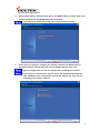
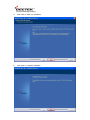
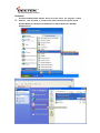
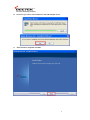
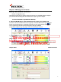
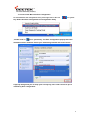
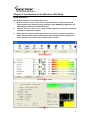
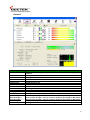
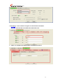
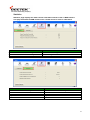
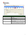
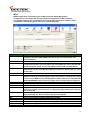
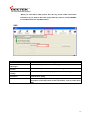
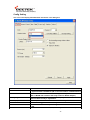
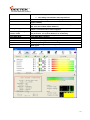
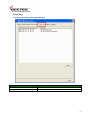
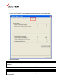
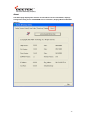
Geetek High Power
For 802.11b/g/n 300Mbps USB Adapter
User Manual
For more info, please visit www.geetek.net www.geetekeurope.com
1
Contents
Chapter 1 Getting Start ....................................................................................................... 3
Minimum System Requirements ...................................................................................3
Optimize Wireless Performance ....................................................................................3
Installation ................................................................................................................. 5
Uninstall ..................................................................................................................... 8
Chapter 2 Management Guide ........................................................................................... 10
Making a Basic Network Connection ........................................................................... 10
Chapter 3 Introduction to the Wireless LAN Utility ............................................................... 13
....................................................................................................... 13
Network ................................................................................................................... 15
Profile ...................................................................................................................... 16
Advanced ................................................................................................................. 18
Statistics .................................................................................................................. 19
Utility Interfaces
WMM ....................................................................................................................... 20
WPS
........................................................................................................................ 21
SSO ......................................................................................................................... 22
CCX ......................................................................................................................... 23
Radio On/Off ............................................................................................................ 24
About ...................................................................................................................... 25
Chapter 4 AP mode management guide .............................................................................. 26
Control Menu............................................................................................................ 27
Config Setting .......................................................................................................... 28
Access Control .......................................................................................................... 30
MAC Table ................................................................................................................ 31
Event Log ................................................................................................................ 32
Statistics .................................................................................................................. 33
About ...................................................................................................................... 34
2
Chapter 1 Getting Start
Minimum System Requirements
®
ś
Pentium 300 MHz or higher compatible processor
ś
At least one available USB 2.0 or 1.1 port
ś
The installation CD
ś
5Mbytes free hard disk space.
ś
Windows 2000, XP, XP professional, Vista, or Windows 7.
If you do not have a USB 2.0 port on your computer, the throughput of the
USB adapter will be limited to the 14 Mbps of the USB 1.1 standard.
Windows XP users must install SP2 or above for the Hot fix which fixes the
USB 2.0 Host controller driver.
Before you proceed with the installation, please notice the following descriptions.
If you have installed the WLAN USB driver & utility before, please uninstall
the old version first.
The following installation was operated under Windows XP. (Procedures are
similar for Windows 98SE/Me/2000.)
The installation guide herein is operated under Windows system. For Linux
or Mac driver installation guide, please refer to the instruction in README
at directory the driver has stored in CD-Rom.
Optimize Wireless Performance
The speed and wireless coverage range of your connection can vary significantly
based on the location of AP/router. You should choose a location for your AP/router
that will maximize the network performance.
You can refer to the following methods to maximize AP/router performance.
Choose placement carefully for your AP/Router.
Place your AP/router at the center among your computers.
Place your AP/router at an elevated location.
3
Avoid obstacles to wireless signals.
Keep your wireless devices far away from metallic file cabinets, refrigerators,
pipes, metal ceilings, reinforced concrete, and metal partitions.
Keep away from large amounts of water such as fish tanks and water coolers.
Reduce interference
Keep away from computers, cordless phones, cell phone, coping machine
and fax machines.
Keep away from microwave oven.
Site survey nearby wireless devices to determine your operating channel.
4
Installation
1.
If you insert the Wireless LAN USB Adaptor into your computer USB port, the following
hardware setup wizard will pop up. Click Cancel to install driver from installation CD.
2.
Insert your installation CD into CD drive of your computer. An installation page
will pop up for you to install. Click Utility Driver.
If the installation page does not appear, double click CD-ROM drive the installation
CD was inserted to, or open the CD-ROM drive then click Autorun.exe
3.
Clink checkbox to accept the terms of license agreement, then click Next
5
4.
Select setup type for installing both driver and WLAN utility or install driver only.
Choose Install driver and WLAN utility, then click Next
If you choose to install driver only, refer to the note on next step .
5.
Select if you are going to configure your wireless network with WLAN utility or
with Microsoft Zero Configuration tool. Choose WLAN Utility then click next.
Type of configuration tool can be changed after installing this software .
If you choose to install driver only on step 4, the installation will skip this
step. Windows Zero Configuration will be the default and only tool for
managing your wireless network.
6
6.
Click Install to begin the installation.
7.
Click Finish to complete installation.
7
Uninstall
A.
Uninstall the WLAN USB Adaptor Driver from start menu, All Programs, Ralink
Wireless, click Uninstall or Control Panel, Add or Remove Programs, Ralink
RT2870 Wireless LAN Card, click Remove to remove Wireless LAN USB
Adaptor driver.
8
B.
Click Yes if you want to remove Wireless LAN USB Adaptor driver.
C.
Click Finish to complete uninstall.
9
Chapter 2 Management Guide
Making a Basic Network Connection
Select a configuration tool
In the following instruction for making a network connection, we use WLAN utility to configure
your wireless network settings that was installed as the steps in previous chapter.
To connect with 802.11 bgn Wireless LAN Utility
As default, the WLAN Utility is started automatically upon starting your computer and
connects to the first available network. It is typically a network with the best signal strength
among unsecured network. To change the connection to your own network, right click the
icon on system tray and select Launch Config Utility. The pop up WLAN
configuration utility allows you to quickly connect the network you intend to.
To join your target network, in Network tab, click on target network then Connect.
Strosngest Unseured
Network
Choose
the
Target Network
security type of your network and type your security key, click on OK to
complete a basic
network connection.
10
To connect with Microsoft Zero Configuration
To switch between the configuration tools, please right click on the icon
on system
tray. Select Use Zero Configuration as Configuration Utility
, double click on
icon on system tray. The Zero Configuration pop up and show
available wireless networks. Select your demanding network and click Connect
A pop up dialog allow you to setup your security key, then click Connect to join a
network by Zero configuration.
11
Chapter 3 Introduction to the Wireless LAN Utility
Utility Interfaces
This Utility is basically consisted of three parts:
1.
Button Section: on top of the window. Include buttons for selecting the Profile
page, Network page, Advanced page, Statistics page, WMM page, WPS page, the
About button, Radio On/Off button and Help.
2.
Function Section: center of the Utility window. Appears to present information
and options related to the button.
3.
Status Section: bottom of the utility window. This section includes information
about the link status, authentication status, AP's information and configuration,
and retrying the connection when authentication is failed.
Button Section
Function Section
Status Section
13
When starting utility, a small utility icon
appears in the system tray of the taskbar.
You can double click it to maximize the dialog box if you selected to close it earlier.
You may also use the mouse's right button to close utility.
Additionally, the small icon will change color to reflect current wireless network
connection status. The status is shown as follows:
: Indicates the connected and signal strength is good.
: Indicates the connected and signal strength is normal.
: Indicates that it is not yet connected.
: Indicates that a wireless NIC can not be detected.
: Indicates that the connection and signal strength is weak.
14
Network
Items
Status
Extra Info
Channel
Authentication
Encryption
Network Type
IP Address
Sub Mask
Default Gateway
Link Speed
Throughput
Link Quality
Signal Strength 1
Signal Strength 2
Signal Strength 3
Noise Strength
HT
Information
Shows the connecting status. Also shows the SSID while connecting to a valid
network.
Display link status in use.
Display current channel in use.
Authentication mode in use.
Encryption type in use.
Network type in use.
IP address of current connection.
Subnet mask of current connection.
Default gateway of current connection.
Show current transmit rate and receive rate.
Display transmit and receive throughput in Mbps.
Display connection quality based on signal strength and TX/RX packet error rate.
Receive signal strength 1, user can choose to display as percentage or dBm format.
Receive signal strength 2, user can choose to display as percentage or dBm format.
Receive signal strength 3, user can choose to display as percentage or dBm format.
Display noise signal strength.
Display current HT status in use, containing BW, GI, MCS, SNR0, and SNR1 value.
15
Profile
This profile page allows users to save different wireless settings, which helps users to
get access to wireless networks at home, office or other wireless network
environments quickly.
Items
Profile Name
SSID
Network Type
Authentication
Encryption
Use 802.1x
Channel
Power Save Mode
Tx Power
RTS Threshold
Fragment Threshold
Information
Choose a name for this profile, or use default name defined by system.
Fill in the intended SSID name or use the drop list to select from available Aps.
There are two types, infrastructure and 802.11 Ad-hoc modes. Under Ad-hoc
mode, you could also choose the preamble type; the available preamble type
includes auto and long. In addition to that, the channel field will be available for
setup in Ad-hoc mode.
Authentication mode.
Encryption mode.
Whether or not use 802.1x feature.
Channel in use for Ad-Hoc mode.
Choose from CAM (Constantly Awake Mode) or PSM (Power Saving Mode).
Transmit power, the amount of power used by a radio transceiver to send the signal
out.
For adjusting the RTS threshold number by sliding the bar or key in the value
directly. The default value is 2347.
Adjust the Fragment threshold number by sliding the bar or key in the value
directly. The default value is 2346.
To add a new profile:
Click the Add button. The add profile dialog pops up.
you could also add a new profile quickly by selecting an available network
in the Network function then click the Add to Profile button.
There are three sub-tabs for fill in information:
1.
System Config: to fill in wireless information of the network
16
2. Auth./Encry.: to fill in wireless encryption or authentication information.
Click Use 802.1X checkbox will enable 802.1x tab
3.
802.1x: to configure the authentication information for 802.1x
17
Advanced
This page provides advanced configurations to this adapter. Please refer to the following chart
for definitions of each item.
Items
Wireless mode
Enable TX Burst
Enable TCP Window Size
Information
Click the drop list to select a wireless mode.
Select to enable connecting to a TX Burst supported device.
Mark the checkbox to enable TCP window size, which help enhance
throughput.
Fast Roaming at __ dBm
Mark the checkbox to enable fast roaming. Specify the transmit power for
fast roaming.
Show Authentication Status
Mark the checkbox to show “Authentication Status Dialog” while
Dialog
connecting to an AP with authentication. Authentication Status Dialog
displays the process about 802.1 x authentications.
Enable CCX (Cisco Compatible Select to enable CCX. This function can only be applied when connecting to
extensions)
a Cisco compatible device.
Turn on CCKM
Mark to enable CCKM.
Enable Radio Measurements
Mark to enable channel measurement every 0~2000 milliseconds.
Select Your Country Region
Code
Eight countries to choose. Channel list:
Classification
0: FCC (Canada)
1: ETSI
2: SPAIN
3: FRANCE
4: MKK
5: MKKI (TELEC)
6: ISRAEL
7: ISRAEL
Range
CH1 ~
CH1 ~
CH10 ~
CH10 ~
CH14 ~
CH1 ~
CH3 ~
CH5 ~
CH11
CH13
CH11
CH13
CH14
CH14
CH9
CH13
18
Statistics
Statistics page displays the detail counter information based on 802.11 MIB counters.
This page translates the MIB counters into a format easier for user to understand.
Items
Frames Transmitted Successfully
Frames Retransmitted Successfully
Frames Fail To Receive ACK After All Retries
Items
Frames Received Successfully
Frames Received With CRC Error
Frames Dropped Due To Out-of-Resource
Duplicate Frames Received
Reset Counter
Information
Frames successfully sent.
Successfully retransmitted frames numbers.
Frames failed transmit after hitting retry limit.
Information
Frames received successfully.
Frames received with CRC error.
Frames dropped due to resource issue.
Duplicate received frames.
Reset counters to zero.
19
WMM
This page allows users to activate the WMM function for this device. Please note that this
function only works while connecting to a WMM compatible device.
Items
WMM Enable
WMM - Power Save Enable
Direct Link Setup Enable
MAC Address
Timeout Value
Apply / Tear Down
Information
Enable Wi-Fi Multi-Media.
Enable WMM Power Save. Please enable WMM before configuring
this function.
Enable DLS (Direct Link Setup). Please enable WMM before
configuring this function.
Fill in the blanks of Direct Link with MAC Address of STA.
Time of automatically disconnect after some seconds. The value is
integer. The integer must be between 0~65535. It represents that
it always connects if the value is zero. Default value of Timeout
Value is 60 seconds.
After fill in the "MAC Address" and "Timeout Value", click "Apply"
button to save your configuration. The result will appear in the
blanks. To remove the configuration, please select the
configuration in the blanks and then click "Tear Down" button.
20
WPS
WPS Configuration: The primary goal of WiFi Protected Setup (WiFi Simple
Configuration) is to simplify the security setup and management of WiFi networks.
This adapter supports the configuration setup using PIN configuration method or PBC
configuration method through an internal or external Registrar.
Items
WPS AP List
Rescan
Information
Pin Code
Config Mode
WPS Profile List
Detail
Connect
Rotate
Disconnect
Delete
PIN
PBC
WPS associate IE
WPS probe IE
Progress Bar
Status Bar
Information
Display the information of surrounding APs with WPS IE from last scan result. List
information includes SSID, BSSID, Channel, ID (Device Password ID), and
Security-Enabled.
Click to rescan the wireless networks.
Display the information about WPS IE on the selected network. List information
includes Authentication Type, Encryption Type, Config Methods, Device Password ID,
Selected Registrar, State, Version, AP Setup Locked, UUID-E and RF Bands.
8-digit numbers. It is required to enter PIN Code into Registrar using PIN method. Each
Network card has only one PIN Code of Enrollee. Click on the Renew button to renew
the PIN code.
Enrollee or an external Registrar.
Display all of credentials got from the Registrar. List information includes SSID, MAC
Address, Authentication and Encryption Type. If STA Enrollee, credentials are created
as soon as each WPS success. If STA Registrar, Utility creates a new credential with
WPA2-PSK/AES/64Hex-Key and doesn't change until next switching to STA Registrar.
Information about Security and Key in the credential.
Command to connect to the selected network inside credentials.
Command to connect to the next network inside credentials.
Stop WPS action and disconnect this active link. And then select the last profile at the
Profile Page of Utility if exists. If there is an empty profile page, the driver will select any
non-security AP.
Delete an existing credential. And then select the next credential if exist. If there is an
empty credential, the driver will select any non-security AP.
Start to add to Registrar using PIN configuration method.
Start to add to AP using PBC configuration method.
Send the association request with WPS IE during WPS setup. It is optional for STA.
Send the probe request with WPS IE during WPS setup. It is optional for STA.
Display rate of progress from Start to Connected status.
Display currently WPS Status.
21
When you click PIN or PBC, please don't do any rescan within two-minute
connection. If you want to abort this setup within the interval, restart PIN/PBC
or click Disconnect to stop WPS action.
SSO
Items
Enable SSO feature
Use ID and Password in
Winlogon:
Use ID and Password in
Profile
Use ID and Password in
Dialog
Enable Persistent
Connection
Profile List
Information
Choose which SSO methods to log on
Use the ID and password in Windows logon
Use the ID and password in RaUI profile settings
Use the ID and password in pop-up authentication dialog
Use ID and Password in the previous activated Profile and not show any
authentication dialog
Select Profile: Select a profile containing LEAP or EAP-Fast authentication
Information of selected profile: Profile information, such as profile name,
SSID.
22
CCX
Items
Information
Enable CCX (Cisco
Choose whether Cisco Compatible eXtensions are supported or not.
Compatible eXtensions)
Enable Radio Measurement Enable the radio measurement; the non-serving channel measurement limit
is between 0 and 1023 milliseconds.
Roaming with RF
Roaming by a set of RF parameters from AP
Parameters
Voice Drastic Roaming
Diagnose roaming function by voice traffic test
CAC (Tolerance)
Enable the call admission control
Diagnostic
Select a profile which the user want to diagnose, then hit the Diagnose
button to perform the diagnostic test
Busy Sense
Force Wireless NIC to detect noise more sensitively
Apply
Hit the Apply button to make the settings effective
23
Radio On/Off
Click on the button to enable/disable wireless connection status.
Radio power on
Radio power off
24
About
Display Configuration Utility, Driver, and EEPROM version information. Display Wireless NIC
MAC address.
25
Chapter 4 AP mode management guide
Clicking
will bring up the selection window and let the user make a selection. It can
switch to AP mode as shown figure.
If "Switch to AP mode" is selected, the system will display default information when
switching to AP mode. The dialog box is shown in figure
26
There are six tabs to configure the settings.
ś
Config Settings: This tab is used to configure Soft AP.
ś
Access Control: This tab is used to edit the access control list.
ś
Mac Table: This tab displays the stations which are currently connected
to Soft AP.
Event Log: This tab displays the Soft AP events.
Statistics: This tab displays the packet counters.
About: This tab displays the Ralink driver and utility information.
ś
ś
ś
Control Menu
When starting Soft AP utility, a small
icon appears within the system tray in winows
taskbar. Double click it to bring up the main menu if the Soft AP utility menu was
closed earlier. The user can also right-click the icon to bring up the control menu.
There are three actions available.
ś
Launch Config Utilities: Restore Ralink Soft AP utility window
ś
Switch to Station Mode: Switch to Station mode
ś
Exit: End Soft AP utility
The icon changes color to reflect the current wireless network connection status. The
status is indicated as follows:
:
Indicate connected and signal strength is good.
Indicate connected and signal strength is normal.
Indicate connected and signal strength is weak.
Indicate wireless NIC not detected.
Indicate not connected yet.
:
27
Config Setting
User can set and display detailed Soft AP information in this dialog box.
Items
SSID
Wireless Mode
Country Region Code
Beacon (ms)
TX Power
Idle Time
Wireless Protection
Information
AP name of user type. The user also can select [Use Mac Address] to display
it. System default is SoftAP-XX (XX is last two numbers of MAC address).
Select wireless mode. 2.4G and 5G are supported. System default is 2.4G.
( 802.11 B/G/N mix selection item only exists for B/G/N adapter )
The Country Region Code allows the user to specify the available channel list
based on their country's regulations.
The time span between two successive4 beacons. System default is 100 ms.
The transmitting power of Soft AP. System default is 100%.
The allowed idle time before proceeding with the authentication. The default
is 300.
The user can chose from Auto, on, and off. System default is auto. (802.11n
28
wireless cards don’t support wireless protection.)
a.
Auto: STA will dynamically change according to the AP.
29
b.
Channel
TX Rate
Use Mac Address
Security Setting
No forwarding among
wireless clients
Hide SSID
Allow BW40 MHz
Default
Cancel
TX Burst
Apply:
On: Always send frames with protection.
c. Off: Always send frames without protection.
Select the AP’s operating channel manually. System default is channel 1.
The transmitting rate. The default is auto. (802.11n wireless cards don’t
support TxRate.)
Use the MAC address of wireless card as the AP’s name. System default is
APX. (X is last number of Mac Address.)
Authentication mode and encryption algorithm used by the AP. The system
default is no authentication and encryption.
If there is no beacon among the wireless clients, they can’t share information
with each other. The system default is no forwarding.
Don’t display the AP name. The system default is to not hide the SSID.
Allow BW40 MHz capability.
Use system default values.
Cancel the any changes without saving.
Ralink’s proprietary frame burst mode. System default is no TX Burst.
Apply the any changes made. If using default values, it will be shown as in
below figure
30
Access Control
AP connected or can’t connect with Mac address that user setting.
Items
Access Policy
Mac Address
Access List
Delete
Remove All
Apply
Information
There are three policies available in the drop-down list. They are Disable,
Allow All, and Reject All. System default is disabled.
In order to add an entry into the access control list, the user should input the
MAC address without "-" in the text box and then click the "Add" button.
Display all Mac Addresses that the user has set.
Delete the Mac address set by user.
Remove all Mac addresses in [Access List].
Apply the above changes.
31
MAC Table
Shows link status. It displays detailed station information of current connection.
Items
MAC Address
AID
Power Saving Mode
Status
Information
The station’s Mac address of the current connection.
The association identifier of the client.
Support Power Saving Mode on the currently connected station.
The link status of the current connection. (Only 802.11n wireless cards
support)
32
Event Log
A record of all events, times and messages.
Items
Event Time (yy/mm/dd-hh:mm:ss)
Message
Information
Specifies when the event occurred.
All event messages.
33
Statistics
The statistics page displays detailed counter information based on the 802.11 MIB
counters. The information is translated into a format easier for the user to understand.
Transmit Statistics
Items
Information
Frames Transmitted Successfully The number of frames sent successfully.
Frames Fail To Receive ACK After The number of frames failed to transmit after hitting the retry limit
All Retries
Frames Retransmitted Successfully The number of successfully retransmitted frames.
Receive Statistics
Items
Frames Received Successfully
Frames Received With CRC Error
Frames Dropped Due To
Out-of-Resource
Information
The number of frames received successfully.
The number of frames received with a CRC error.
The number of frames stopped due to insufficient resources
34
Duplicate Frames Received
Reset counters
The number of duplicate frames received.
Reset counters to zero.
35
About
The About page displays the wireless card and driver version information, displays
Configuration Utility, driver and EEPROM version information, displays Wireless NIC MAC
address.
36


![User Manual - [ [ [ ANSEL ] ] ]](http://vs1.manualzilla.com/store/data/005966842_1-ae62d22d0a4b66fbc237bfe063bfcd99-150x150.png)