Transcript
Triple optical baseband video receiver A115 model, User Manual
INITIAL INSPECTION
Please, check that the contents of the consignment are
correct and verify that no element has been damaged
during the transport. In case of mistaken or damaged
material, please state an immediate claim to the transport
carrier and notify it immediately to the manufacturer or
distributor, either for a new remittance or for the repair or
replacement of the damaged material.
SAFETY CONSIDERATIONS
All the devices described in this manual have been
designed to be properly performed by qualified technical
personnel only. Personnel skilled enough to foresee the
possible consequences of inadequate handling, must carry
out the installation, setting, maintenance or repair of this
equipment.
DESCRIPTION
Baseband video links have been designed for the
transmission of soundless television image through optical
fibre. Optimum applications are those of CCTV security
systems, remote monitoring in industrial processes, traffic
control, etc.
The use of fibre-optic technology in this equipment allows
its application to long distance transmission, thanks to the
low attenuation of the fibre. It also allows transmission
through hostile electromagnetic environment, thanks to its
immunity to this kind of interference.
For a correct and safe use of the provided equipment and
in order to achieve the best possible security conditions, it
is essential to follow not only general security procedures
but also the special ones described in this manual.
EQUITEL A115 is an optical receiver for three baseband
video signals through three optical fibres, employing as
light detector a PIN photodiode. It has been designed to be
used with one of EQUITEL's compatible optical emitters.
The mechanical format of A115 is a 3U high and 5TE wide
module, to be inserted into a 19” 3U high housing of
EQUITEL series P400. The power supply is internal and it
comes directly from the housing system.
Never switch on the systems in case there is the
smallest suspicion of bad functioning.
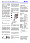
The following photograph indicates the most important
parts of this device.
For instance, in case of detecting apparent damages which
could be consequence of transport or storage, etc.
Before any setting or maintenance operation,
disconnect the equipment from any power supply or
optical emitter. After electrical disconnection, inside
capacitors could remain loaded for one second.
Active power circuitry could appear when protecting lids or
coverings are taken away. Likewise, unplugged optical
connectors must be immediately covered with the
corresponding protecting caps.
In case the equipment needs to be checked while it is
functioning, remember that maintenance operations can
only be carried out by qualified technical personnel who is
aware of the risks of the operation, both from the electrical
and optical point of view.
The security classification of this product is Class III.
The modification of the electrical protection elements
and the disconnection of the earth terminal may result
in personal injury.
Before the equipment is switched on, make sure that it has
been properly grounded (through the protective conductor
of the a.c. power cable) to a socket outlet provided with
protective earth contact.
The earth circuit cover of the electrical external connectors
must not be used as protective general earth contact for
the equipment.
The optical transmitters could cause safety problems
to the personnel in charge of the installation, test,
service or maintenance of the equipment. This is due
to the high level of optical power in some fibre-optic
installations and to the fact that light radiation is
infrared type (not visible for the human eye).
In consequence, never look directly either at the
optical output of an optical transmitter, or at the end of
an optical fibre connected to an active optical
transmitter. This situation will be especially dangerous
when the inspection takes place with the assistance of
light focusing elements, magnifying glasses,
microscopes, etc.
In case these recommendations are not followed, eyes
would be exposed to a level of light radiation that
would be higher than the maximum admissible level.
This could result in permanent and irreversible
damages in eyes.
LASER RADIATION
DO NOT STARE INTOBEAM OR VIEW
DIRECTLY WITH OPTICAL
INSTRUMENTS
CLASS 3A LASER PRODUCT
The use of controls, adjustments or procedures
different from the ones specified here, could cause a
dangerous exposure to radiation.
1
2
3
4
5
Fastening screws
Optical signal input connector
Video signal output connector
NV and AP indicator LEDs
ON-indicator LED
INSTALLATION
First switch off the housing system (EQUITEL series P400)
where it will be placed, which is provided with power
supply. Always following the instructions given in P400
user’s manuals, insert the module in any of the slots
available in the housing and fix it with the fastening screws
(1 in the figure).
The fibre jumper will be introduced in the optical connector
(2 in the figure) after the protective cover of the connector
is removed. The protector must be kept to be replaced in
case the optical connection is temporary removed.
Do not connect unless you have previously cleaned
the single-fibre cable connector with a soft paper
dampened with alcohol. Introduce the connector
carefully in the optical sign input in order to avoid
damages in the polished surface.
- Protect the optical connector of the equipment with the
original protector cap every time it is going to be
disconnected for a long time. Excessive environmental
dust and humidity must be avoided during this
maintenance phase.
- These operations must be carried out only by personnel
trained in the handling of optical fibre and connectors.
The introduction of strange mechanical elements in
the optical connector may result in irreparable damage
in the optical components.
TECHNICAL CHARACTERISTICS
OPTICAL PARAMETERS
Optical receiver
Wavelength (note 1)
PIN
850 nm (CM version)
1,310 nm (D version)
1,310 & 1,550 nm (A version)
Type of fibre
Singlemode (A version)
Multimode (CM, D versions)
Sensitivity (note 1)
≤ 30 dBm (A,D versions)
≤ 28 dBm (CM version)
ELECTRICAL PARAMETERS
Video system
PAL, NTSC, SECAM
Output voltage
1 Vpp (75 Ω)
Output video level
Automatically controlled
Output impedance
75 Ω (note 2)
Bandwidth (-3 dB)
≥ 5.5 MHz (note 1)
Differential gain
< 3.5 % (notes 1, 2)
Differential phase
< 3.5 ° (notes 1, 2)
Signal to noise ratio
> 45 dB (notes 1, 2 and 3)
POWER PARAMETERS
Power requirements
Internal of P40W
Power consumption (note 2) < 3 W
MECHANICAL PARAMETERS
Format
Plug in module for 19" rack
3U high
Dimensions
5 TE wide, 160 mm deep
(without connectors)
Optical connector
FC/PC (A version)
ST (CM, D versions)
Video connector
BNC
ENVIRONMENTAL CONDITIONS
Operating temperature range -40 ºC to +74 ºC
Humidity range
0to95% without condensation
INDICATORS AND ALARMS (note 4)
Unit in operation
Green
ON
No video output signal
Red
NV
Low optical input power
Red
AP
Note 1.Note 2.-
Note 3.Note 4.-
Typical values, as a production average
Actual values are given in the test sheet. These
values are measured according to the test
procedure for this device
Value to the receiver sensitivity in all the
operating range
LEDs on the front side
Then switch on the P400 housing and check that the Onindicator LED (5 in the figure) turns on.
There has to be a compatible optical emitter already
installed and in operation at the opposite end of the link,
and it has to transmit a signal which is appropriate for
video signal measurements. In case no video signal is
detected, the NV LED (4 in the figure) turns on. If the input
optical power level is under the specified levels, the AP
LED (4 in the figure) activates.
A coax cable ended with a BNC connector will be plugged
to the video signal output connector (3 in the figure). The
equipment does not require any electrical fitting for its
correct operation, since it is provided with automatic gain
control and delivers an output electrical level of 1Vpp.
Follow the same steps with the second and third channel
of A115.
OPERATION
Once the equipment is installed, it does not require any
additional attention for its correct operation.
MAINTENANCE
This equipment has been designed to require no
maintenance periodical operations and to keep a good
long-term stability.
In order to prolong the life of the equipment, the following
rules in optical connection and disconnection must be
observed:
Ed. 1.0
- The optical output connectors must be thoroughly
cleaned before connecting the equipment. Use an opticalcleaning paper or gauze dampened with ethylic or
isopropilic alcohol. Dry carefully the connector afterwards.
The information included in this manual cannot be copied
or reproduced in any way without the previous written
authorisation
of
Equipos
de
Telecomunicación
Optoelectrónicos, S.A.
Equipos de Telecomunicación Optoelectrónicos, S.A.
Polígono de Malpica, c/ F oeste, G. Quejido, nave 74
50057 Zaragoza SPAIN
Tel. +34 976 570 353
Fax +34 976 571 383
E-mail: [email protected]
www.equitel.es
Published by Equipos de Telecomunicación Optoelectrónicos, S.A. (Zaragoza, January 2004)