1
FUJITSU Server
PRIMEQUEST 1000 Series
Administration Manual
C122-E108-10EN
PRIMEQUEST 1000 Series Administration Manual
Preface
Preface
This manual describes how to use tools and software for system administration of the PRIMEQUEST 1000 series
system and how to maintain the system (component replacement and error notification). The manual is intended
for system administrators.
For details on the regulatory compliance statements and safety precautions, see the PRIMEQUEST 1000 Series
Safety and Regulatory Information (C122-E115XA).
Errata and addenda for the manual
The PRIMEQUEST 1000 Series Errata and Addenda (C122-E119EN) provides errata and addenda for the manual.
Read the PRIMEQUEST 1000 Series Errata and Addenda (C122-E119EN) thoroughly in reference to the manual.
For Safe Operation
How to use this manual
This manual contains important information about the safe use of this product. Read the manual thoroughly to
understand the information in it before using this product. Be sure to keep this manual in a safe and convenient
location for quick reference.
Fujitsu makes every effort to prevent users and bystanders from being injured and to prevent property damage. Be
sure to use the product according to the instructions in the manual.
About this product
This product is designed and manufactured for standard applications. Such applications include, but are not limited
to, general office work, personal and home use, and general industrial use. The product is not intended for
applications that require extremely high levels of safety to be guaranteed (referred to below as "safety-critical"
applications). Use of the product for a safety-critical application may present a significant risk of personal injury
and/or death. Such applications include, but are not limited to, nuclear reactor control, aircraft flight control, air
traffic control, mass transit control, medical life support, and missile launch control. Customers shall not use the
product for a safety-critical application without guaranteeing the required level of safety. Customers who plan to
use the product in a safety-critical system are requested to consult the Fujitsu sales representatives in charge.
Storage of accessories
Keep the accessories in a safe place because they are required for server operation.
Organization and Notation of This Manual
This section describes the following topics:
-
Organization of this manual
Manuals for the PRIMEQUEST 1000 series
Related manuals
Abbreviations
Notation
Notation for the CLI (command line interface)
Notes on notations
Alert messages
i
C122-E108-10EN
PRIMEQUEST 1000 Series Administration Manual
Preface
- Product operating environment
- Trademarks
Organization of this manual
This manual is organized as follows.
CHAPTER 1 Network Environment Setup and Tool Installation
Chapter 1 describes the external network environment and management tool installation for the
PRIMEQUEST 1000 series.
CHAPTER 2 Operating System Installation (Link)
Chapter 2 provides a link to Chapter 4 Installing the Operating System and Bundled Software in the
PRIMEQUEST 1000 Series Installation Manual (C122-E107EN).
CHAPTER 3 Component Configuration and Replacement (Addition and Removal)
Chapter 3 describes the component configuration and how to replace, add, and remove components for the
PRIMEQUEST 1000 series.
CHAPTER 4 Hot Replacement of Hard Disks
Chapter 4 describes hot replacement of hard disks.
CHAPTER 5 PCI Card Hot Maintenance in Red Hat Enterprise Linux 5
Chapter 5 describes hot maintenance of PCI cards in Red Hat Enterprise Linux.
CHAPTER 6 PCI Card Hot Maintenance in Red Hat Enterprise Linux 6
Chapter 6 describes the methods of PCI card replacement with the PCI Hot Plug function.
CHAPTER 7 PCI Card Hot Maintenance in Windows
Chapter 7 describes the hot plugging procedure for PCI cards in Windows.
CHAPTER 8 Backup and Restore
Chapter 8 describes the backup and restore operations required for restoring server data.
CHAPTER 9 System Startup, Shutdown, and Power Control
Chapter 9 describes how to start and shut down the system, and control the system power.
CHAPTER 10 Configuration and Status Checking (Contents, Methods, and Procedures)
Chapter 10 describes functions for checking the configuration and status of the PRIMEQUEST 1000 series
server. The functions are broken down by firmware (or other software) and by tool.
CHAPTER 11 Error Notification and Maintenance (Contents, Methods, and Procedures)
Chapter 11 describes the maintenance functions provided by the PRIMEQUEST 1000 series. It also describes
actions to take for any problems that occur.
APPENDIX A Functions Provided by the PRIMEQUEST 1000 Series
Appendix A lists the functions provided by the PRIMEQUEST 1000 series.
APPENDIX B Physical Mounting Locations and Port Numbers
Appendix B describes the physical mounting locations of components, and shows GSPB and MMB port
numbering.
APPENDIX C Lists of External Interfaces
Appendix C describes the external interfaces of the PRIMEQUEST 1000 series.
ii
C122-E108-10EN
PRIMEQUEST 1000 Series Administration Manual
Preface
APPENDIX D Physical Locations and BUS Numbers of Built-in I/O, and PCI Slot Mounting Locations and Slot
Numbers
Appendix D shows the correspondence between the physical locations and BUS numbers of built-in I/O in
the PRIMEQUEST 1000 series server. It also shows the correspondence between PCI slot mounting locations
and slot numbers.
APPENDIX E PRIMEQUEST 1000 Series Cabinets (Link)
Appendix E provides a link to Chapter 1 Installation Information in the PRIMEQUEST 1000 Series Hardware
Installation Manual (C122-H004EN).
APPENDIX F Status Checks with LEDs
Appendix F describes the types of mounted LEDs for the PRIMEQUEST 1000 series. It also describes how
to check the status with the LEDs.
APPENDIX G Component Mounting Conditions
Appendix G describes the mounting conditions of components for the PRIMEQUEST 1000 series.
APPENDIX H Tree Structure of the MIB Provided with the PRIMEQUEST 1000 Series
Appendix H describes the tree structure of the MIB provided with the PRIMEQUEST 1000 series.
APPENDIX I Windows Shutdown Settings
Appendix I describes how to set Windows to shut down, and some precautions about the settings.
APPENDIX J Systemwalker Centric Manager Linkage
Appendix J describes linkage with Systemwalker Centric Manager.
APPENDIX K How to Confirm Firmware of SAS Array Controller Card
Appendix K describes how to confirm the firmware of SAS array controller card (including the one contained
in the SAS array disk unit).
APPENDIX L Software (Link)
Appendix L provides a link to Chapter 3 Software Configuration in the PRIMEQUEST 1000 Series General
Description (C122-B022EN).
APPENDIX M Failure Report Sheet
Appendix M provides the failure report sheet. Use the sheet when any failure occurs.
Index
The index lists keywords and the pages that they refer to, helping readers quickly find the necessary
information in the manual.
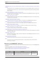
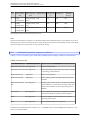
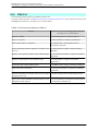
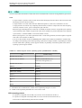
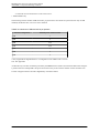
Manuals for the PRIMEQUEST 1000 series
The following manuals have been prepared to provide you with the information necessary to use the PRIMEQUEST
1000 series.
You can access HTML versions of these manuals at the following sites:
Japanese-language site: http://jp.fujitsu.com/platform/server/primequest/manual/
Global site: http://jp.fujitsu.com/platform/server/primequest/manual-e/
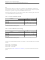
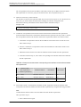
Title
Description
PRIMEQUEST 1000 Series Describes what manuals you should read and how to
Getting Started Guide
access important information after unpacking the
iii
Manual code
C122-E114XA
C122-E108-10EN
PRIMEQUEST 1000 Series Administration Manual
Preface
Title
Description
Manual code
PRIMEQUEST 1000 series server. (This manual comes
with the product.)
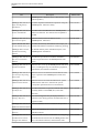
PRIMEQUEST 1000 Series Contains important information required for using the
Safety and Regulatory
PRIMEQUEST 1000 series safely.
Information
C122-E115XA
PRIMEQUEST 1000 Series Provides errata and addenda for the PRIMEQUEST
Errata and Addenda
1000 series manuals. This manual will be updated as
needed.
C122-E119EN
PRIMEQUEST 1000 Series Describes the functions and features of the
General Description
PRIMEQUEST 1000 series.
C122-B022EN
Fujitsu M10/SPARC M10
Systems/SPARC Enterprise/
PRIMEQUEST Common
Installation Planning
Manual
Provides the necessary information and concepts you C120-H007EN
should understand for installation and facility planning
for SPARC M10 Systems, SPARC Enterprise, and
PRIMEQUEST installations.
PRIMEQUEST 1000 Series Includes the specifications of and the installation
Hardware Installation
location requirements for the PRIMEQUEST 1000
Manual
series.
C122-H004EN
PRIMEQUEST 1000 Series Describes how to set up the PRIMEQUEST 1000 series C122-E107EN
Installation Manual
server, including the steps for installation preparation,
initialization, and software installation.
PRIMEQUEST 1000 Series Describes how to use the Web-UI and UEFI to assure
User Interface Operating
proper operation of the PRIMEQUEST 1000 series
Instructions
server.
C122-E109EN
PRIMEQUEST 1000 Series Describes how to use tools and software for system
Administration Manual
administration and how to maintain the system
(component replacement and error notification).
C122-E108EN
PRIMEQUEST 1000 Series Provides information on operation methods and settings, C122-E110EN
Tool Reference
including details on the MMB, PSA, and UEFI
functions.
PRIMEQUEST 1000 Series Lists the messages that may be displayed when a
C122-E111EN
Message Reference
problem occurs during operation and describes how to
respond to them.
PRIMEQUEST 1000 Series Describes REMCS service installation and operation.
REMCS Installation Manual
C122-E120EN
PRIMEQUEST 1000 Series Defines the PRIMEQUEST 1000 series related terms
Glossary
and abbreviations.
C122-E116EN
PRIMEQUEST 1000 Series Gives a revised version of APPENDIX D Configuring C122-E155EN
SAN Boot Environment
the SAN Boot Environment in the PRIMEQUEST 1000
Configuration Manual
Series Installation Manual (C122-E107EN). This
iv
C122-E108-10EN
PRIMEQUEST 1000 Series Administration Manual
Preface
Title
Description
Manual code
manual describes procedures for installing the SAN boot
environment and provides the latest information
including notes on design.
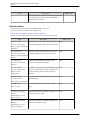
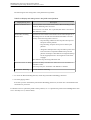
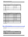
Related manuals
The following manuals relate to the PRIMEQUEST 1000 series.
You can access these manuals at the following site:
http://jp.fujitsu.com/platform/server/primequest/manual-e/
Contact your sales representative for inquiries about the ServerView manuals.
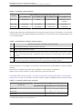
Title
Description
Manual code
ServerView Suite
Describes how to install and start ServerView
None
ServerView Operations
Operations Manager in a Windows environment.
Manager Quick Installation
(Windows)
ServerView Suite
Describes how to install and start ServerView
ServerView Operations
Operations Manager in a Linux environment.
Manager Quick Installation
(Linux)
None
ServerView Suite
ServerView Installation
Manager
Describes the installation procedure using
ServerView Installation Manager.
None
ServerView Suite
ServerView Operations
Manager Server
Management
Provides an overview of server monitoring using None
ServerView Operations Manager, and describes
the user interface of ServerView Operations
Manager.
ServerView Suite
ServerView RAID
Management User Manual
Describes RAID management using ServerView None
RAID Manager.
ServerView Suite
Basic Concepts
Describes the basic concepts of ServerView
Suite.
ServerView Operations
Manager
Installation ServerView
Agents for Linux
Describes installation and update installation of None
ServerView Linux Agent.
ServerView Operations
Manager
Installation ServerView
Agents for Windows
Describes installation and update installation of None
ServerView Windows Agent.
v
None
C122-E108-10EN
PRIMEQUEST 1000 Series Administration Manual
Preface
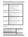
Title
Description
ServerView Mission
Critical Option User
Manual
Manual code
Describes the necessary functions unique to
None
PRIMEQUEST (notification via the MMB, hot
replacement command) and ServerView Mission
Critical Option (SVmco), which is required for
supporting these functions.
Also includes explanation of ServerView
Mission Critical Option for VM (SVmcovm)
required for VMware vSphere 5 server monitor.
ServerView RAID Manager Describes the installation and settings required to None
VMware vSphere ESXi 5
use ServerView RAID Manager on the VMware
Installation Guide
vSphere ESXi 5 server.
MegaRAID SAS Software
Provides technical information on using array
None
controllers. Refer to the manual from the SVSDVD2 supplied with the product or from the
following URL:
The Fujitsu Technology Solutions manuals server
http://manuals.ts.fujitsu.com/
MegaRAID SAS Device
Provides technical information on using array
Driver Installation
controllers. Refer to the manual from the SVSDVD2 supplied with the product or from the
following URL:
The Fujitsu Technology Solutions manuals server
http://manuals.ts.fujitsu.com/
Modular RAID Controller
Provides technical information on using array
Installation Guide
controllers. Refer to the manual from the SVSDVD2 supplied with the product or from the
following URL:
The Fujitsu Technology Solutions manuals server
http://manuals.ts.fujitsu.com/
None
None
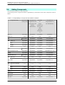
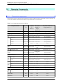
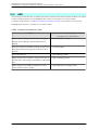
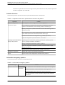
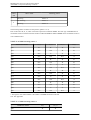
Abbreviations
This manual uses the following product name abbreviations.
Formal product name
Abbreviation
Red Hat® Enterprise Linux® 5 (for Intel 64)
Linux
RHEL5, RHEL
Red Hat® Enterprise Linux® 5 (for x86)
Red Hat® Enterprise Linux® 6 (for Intel 64)
Linux
RHEL6, RHEL
Red Hat® Enterprise Linux® 6 (for x86)
Microsoft® Windows Server® 2003, Standard Edition
Windows
Windows Server 2003
vi
C122-E108-10EN
PRIMEQUEST 1000 Series Administration Manual
Preface
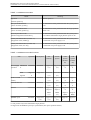
Formal product name
Abbreviation
Microsoft® Windows Server® 2003, Enterprise Edition
Microsoft® Windows Server® 2003, Datacenter Edition
Microsoft® Windows Server® 2003, Standard x64 Edition
Microsoft® Windows Server® 2003, Enterprise x64 Edition
Microsoft® Windows Server® 2003, Datacenter x64 Edition
Microsoft® Windows Server® 2003 R2, Standard Edition
Microsoft® Windows Server® 2003 R2, Enterprise Edition
Microsoft® Windows Server® 2003 R2, Datacenter Edition
Microsoft® Windows Server® 2003 R2, Standard x64 Edition
Microsoft® Windows Server® 2003 R2, Enterprise x64 Edition
Microsoft® Windows Server® 2003 R2, Datacenter x64 Edition
Microsoft® Windows Server® 2008 Standard
Windows
Windows Server 2008
Microsoft® Windows Server® 2008 Enterprise
Microsoft® Windows Server® 2008 Datacenter
Microsoft® Windows Server® 2008 R2 Standard
Microsoft® Windows Server® 2008 R2 Enterprise
Microsoft® Windows Server® 2008 R2 Datacenter
Microsoft(R) Windows Server(R) 2012 Datacenter
Microsoft(R) Windows Server(R) 2012 Standard
Windows
Windows Server 2012
VMware vSphere(R) 4
vSphere 4, VMware 4
VMware vSphere(R) 5
vSphere 5, VMware 5
VMware(R) ESX(TM) 4
ESX, ESX 4.x
VMware(R) ESXi(TM) 5
ESXi, ESXi 5.x
Novell(R) SUSE(R) LINUX Enterprise Server 11 Service Pack 2
SLES11 SP2
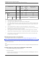
Notation
This manual uses the following fonts and symbols to express specific types of information.
Font or
symbol
italics
Meaning
Example
Title of a manual that you should refer to
See the PRIMEQUEST 1000 Series
Installation Manual (C122-E107EN).
vii
C122-E108-10EN
PRIMEQUEST 1000 Series Administration Manual
Preface
Font or
symbol
[]
Meaning
Example
Window names as well as the names of buttons,
tabs, and drop-down menus in windows are
enclosed in brackets.
Click the [OK] button.
Notation for the CLI (command line interface)
The following notation is used for commands.
Command syntax
Command syntax is represented as follows.
- Variables requiring the entry of a value are enclosed in angle brackets < >.
- Optional elements are enclosed in brackets [ ].
- Options for optional keywords are grouped in | (stroke) separated lists enclosed in brackets [ ].
- Options for required keywords are grouped in | (stroke) separated lists enclosed in braces { }.
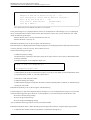
Command syntax is written in a box.
Remarks
The command output shown in the PDF manuals may include line feeds at places where there is no line feed symbol
(\ at the end of the line).
Notes on notations
- In this manual, the Management Board and MMB firmware are abbreviated as "MMB."
- In this manual, IOBs and GSPBs (LIOBs and LGSPBs within partitions) are collectively referred to as IO
Units.
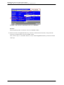
- Screenshots contained in this manual may differ from the actual product screen displays.
- The IP addresses, configuration information, and other such information contained in this manual are display
examples and differ from that for actual operation.
Alert messages
This manual uses the following alert messages to prevent users and bystanders from being injured and to prevent
property damage.
This indicates a hazardous situation that is likely to result in death or serious personal injury
if the user does not perform the procedure correctly.
This indicates a hazardous situation that could result in minor or moderate personal injury
if the user does not perform the procedure correctly. This also indicates that damage to the
product or other property may occur if the user does not perform the procedure correctly.
This indicates information that could help the user use the product more efficiently.
Alert messages in the text
viii
C122-E108-10EN
PRIMEQUEST 1000 Series Administration Manual
Preface
An alert statement follows an alert symbol. An alert statement is indented on both ends to distinguish it from regular
text. Similarly, one space line is inserted before and after the alert statement.
Only Fujitsu certified service engineers should perform the following tasks on this product
and the options provided by Fujitsu. Customers must not perform these tasks under any
circumstances. Otherwise, electric shock, injury, or fire may result.
- Newly installing or moving equipment
- Removing the front, rear, and side covers
- Installing and removing built-in options
- Connecting and disconnecting external interface cables
- Maintenance (repair and periodic diagnosis and maintenance)
The List of important alert items table lists important alert items.
Product operating environment
This product is a computer intended for use in a computer room environment. For details on the product operating
environment, see the following manual:
PRIMEQUEST 1000 Series Hardware Installation Manual (C122-H004EN)
Note
- If you have a comment or request regarding this manual, or if you find any part of this manual unclear, please
take a moment to share it with us by filling in the form at the following webpage, stating your points
specifically, and sending the form to us:
https://www-s.fujitsu.com/global/contact/computing/PRMQST_feedback.html
- The contents of this manual may be revised without prior notice.
- The PDF file of this manual is intended for display using Adobe® Reader® in single page viewing mode at
100% zoom.
- The PRIMEQUEST 1800E2/1800E model supports only 200 V power supply.
Trademarks
- Microsoft, Windows, and Windows Server are trademarks or registered trademarks of Microsoft Corporation
in the United States and/or other countries.
- Linux is a registered trademark of Linus Torvalds.
- Red Hat, the Shadowman logo and JBoss are registered trademarks of Red Hat, Inc. in the U.S. and other
-
countries.
Intel and Xeon are trademarks or registered trademarks of Intel Corporation.
Ethernet is a registered trademark of Fuji Xerox Co., Ltd. in Japan and is a registered trademark of Xerox
Corp. in the United States and other countries.
VMware is a trademark or registered trademark of VMware, Inc. in the United States and other countries.
Novell and SUSE Linux Enterprise Server are trademarks of Novell, Inc.
Xen is a trademark or registered trademark of Citrix Systems, Inc. or its subsidiaries in the United States and
other countries.
Other company names and product names are the trademarks or registered trademarks of their respective
owners.
Trademark indications are omitted for some system and product names in this manual.
ix
C122-E108-10EN
PRIMEQUEST 1000 Series Administration Manual
Preface
Safety Precautions
List of important alert items
This manual does not contain important alert items.
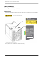
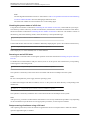
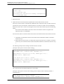
Warning labels
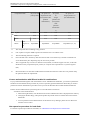
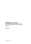
The following warning labels are affixed to this product. These labels are intended for the users of this product.
Never remove the warning labels.
* The label is affixed at either location.
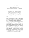
Warning label location (PRIMEQUEST 1800E2/1800E rear)
x
C122-E108-10EN
PRIMEQUEST 1000 Series Administration Manual
Preface
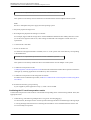
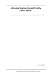
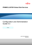
Warning label location (PRIMEQUEST 1800E2/1800E rear) (IOBs removed)
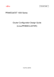
Warning label location (PCI_Box)
xi
C122-E108-10EN
PRIMEQUEST 1000 Series Administration Manual
Preface
Notes on Handling the Product
Adding optional products
For stable operation of the PRIMEQUEST 1000 series server, use only a Fujitsu certified optional product as an
added option.
Note that the PRIMEQUEST 1000 series server is not guaranteed to operate with any optional product not certified
by Fujitsu.
Maintenance
Only Fujitsu certified service engineers should perform the following tasks on this
product and the options provided by Fujitsu. Customers must not perform these tasks
under any circumstances. Otherwise, electric shock, injury, or fire may result.
- Newly installing or moving equipment
- Removing the front, rear, and side covers
- Installing and removing built-in options
- Connecting and disconnecting external interface cables
- Maintenance (repair and periodic diagnosis and maintenance)
Only Fujitsu certified service engineers should perform the following tasks on this
product and the options provided by Fujitsu. Customers must not perform these tasks
under any circumstances. Otherwise, product failure may result.
- Unpacking an optional Fujitsu product, such as an optional adapter, delivered to
the customer
Modifying or recycling the product
Modifying this product or recycling a secondhand product by overhauling it without prior
approval may result in personal injury to users and/or bystanders or damage to the product
and/or other property.
Note on erasing data from hard disks when disposing of the product or transferring
it
Disposing of this product or transferring it as is may enable third parties to access the data on the hard disk and use
it for unforeseen purposes. To prevent the leakage of confidential information and important data, all of the data
on the hard disk must be erased before disposal or transfer of the product.
However, it can be difficult to completely erase all of the data from the hard disk. Simply initializing (reformatting)
the hard disk or deleting files on the operating system is insufficient to erase the data, even though the data appears
at a glance to have been erased. This type of operation only makes it impossible to access the data from the operating
system. Malicious third parties can restore this data.
If you save your confidential information or other important data on the hard disk, you should completely erase the
data, instead of simply carrying out the aforementioned operation, to prevent the data from being restored.
xii
C122-E108-10EN
PRIMEQUEST 1000 Series Administration Manual
Preface
To prevent important data on the hard disk from being leaked when the product is disposed of or transferred, you
will need to take care to erase all the data recorded on the hard disk on your own responsibility.
Furthermore, if a software license agreement restricts the transfer of the software (operating system and application
software) on the hard disk in the server or other product to a third party, transferring the product without deleting
the software from the hard disk may violate the agreement. Adequate verification from this point of view is also
necessary.
Support and service
SupportDesk (available only in Japan, for a fee)
For stable system operation, we recommend concluding our SupportDesk agreement, which provides a maintenance
and operation support service. SupportDesk agreement customers receive a same-day response service for hardware
problems. They are eligible for regular checkups, remote notification of potential-failure predictions, and
information on system problems. Moreover, they can avail themselves of other services such as troubleshooting
support by phone for hardware and software problems, and access to operation support information from a dedicated
website for our customers. For details, see "Product support" on the SupportDesk webpage (http://jp.fujitsu.com/
solutions/support/sdk/index.html).
Product and service inquiries
For all product use and technical inquiries, contact the distributor where you purchased your product, or a Fujitsu
sales representative or systems engineer (SE). If you do not know the appropriate contact address for inquiries about
the PRIMEQUEST 1000 series, use the Fujitsu contact line.
Fujitsu contact line
We accept Web inquiries. For details, visit our website:
https://www-s.fujitsu.com/global/contact/computing/PRMQST_feedback.html
Warranty
If a component failure occurs during the warranty period, we will repair it free of charge in accordance with the
terms of the warranty agreement. For details, see the warranty.
Before requesting a repair
If a problem occurs with the product, confirm the problem by referring to 11.2 Troubleshooting in this manual. If
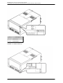
the error recurs, contact your sales representative or a field engineer. Confirm the model name and serial number
shown on the label affixed to the right front of the device and report it. Also check any other required items
beforehand according to 11.2 Troubleshooting. The system settings saved by the customer will be used during
maintenance.
Revision History
Edition
Date
Revised location (type) (*)
Description
01
2010-02-09 -
-
02
2010-03-12 All pages
Incorporated differences in Errata and
Addenda (C122-E119-01EN)
xiii
C122-E108-10EN
PRIMEQUEST 1000 Series Administration Manual
Preface
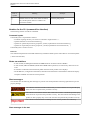
Edition
Date
Revised location (type) (*)
Description
2010-08-20 All pages
Incorporated differences in Errata and
Addenda (C122-E119-02EN to C122E119-10EN)
04
2011-04-28 All pages
- Added items about 1800E2
- Incorporated differences in
Errata and Addenda (C122E119-11EN to C122E119-18EN)
05
2011-05-31 All pages
Incorporated differences in Errata and
Addenda (C122-E119-19EN)
2011-12-20 All pages
Incorporated differences in Errata and
Addenda (C122-E119-20EN to C122E119-24EN)
2012-07-17 All pages
Changed and added descriptions
mainly concerning the following items.
- Video redirection notes
- Stopping the ServerView RAID
service
- FC card replacement procedure
and explanation
- [ASR Control] window display/
setting items
- [Partition Event Log] window
03
06
07
08
2013-01-25 All pages
09
2013-07-02
10
- Added descriptions about
Windows Server 2012
- Added descriptions about 785
GB/1.2 TB internal solid-state
drives that use PCI slots
Chapter 3
Chapter 11
Added descriptions about GSPB
replacement
- Added descriptions to Notes on
VMware in 3.2.1 Reserved SB
- Added descriptions on Windows
Software RAID and Windows
configuration
2013-11-19 Chapter 3
* Chapter, section, and item numbers in the "Revised location" column refer to those in the latest edition of the
document. However, a number marked with an asterisk (*) denotes a chapter, section, or item in a previous edition
of the document.
This manual shall not be reproduced or copied without the permission of Fujitsu Limited.
Copyright 2010 - 2013 FUJITSU LIMITED
xiv
C122-E108-10EN
PRIMEQUEST 1000 Series Administration Manual
Contents
Contents
CHAPTER 1 Network Environment Setup and Tool Installation ........................................................................ 1
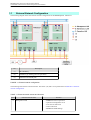
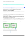
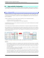
1.1 External Network Configuration ................................................................................................................ 2
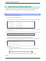
1.2 How to Configure the External Networks (Management LAN/Maintenance LAN/Production LAN) .......... 4
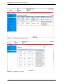
1.2.1 IP addresses used in the PRIMEQUEST 1000 series server ............................................................. 4
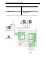
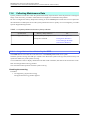
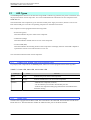
1.3 Management LAN ..................................................................................................................................... 8
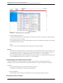
1.3.1 Overview of the management LAN ...................................................................................................... 8
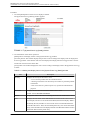
1.3.2 How to configure the management LAN ........................................................................................... 10
1.3.3 Redundant configuration of the management LAN ........................................................................... 14
1.4 Maintenance LAN/REMCS LAN ............................................................................................................. 16
1.5 Production LAN ....................................................................................................................................... 17
1.5.1 Overview of the production LAN ........................................................................................................ 17
1.5.2 Redundancy of the production LAN .................................................................................................. 17
1.6 Management Tool Operating Conditions and Use .................................................................................. 18
1.6.1 MMB .................................................................................................................................................. 18
1.6.2 PSA .................................................................................................................................................. 19
1.6.3 Remote operation (BMC) .................................................................................................................. 19
1.6.4 ServerView Suite .............................................................................................................................. 41
CHAPTER 2 Operating System Installation (Link) ........................................................................................... 43
CHAPTER 3 Component Configuration and Replacement (Addition and Removal) ....................................... 44
3.1 Partition Configuration ............................................................................................................................ 45
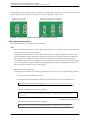
3.1.1 Examples of partition configurations .................................................................................................. 45
3.1.2 Partition setup procedure using the MMB Web-UI ............................................................................ 46
3.2 High-availability Configuration ................................................................................................................ 48
3.2.1 Reserved SB ..................................................................................................................................... 48
3.2.2 Memory Mirror ................................................................................................................................... 57
3.2.3 Hardware RAID ................................................................................................................................. 59
3.2.4 ServerView RAID ............................................................................................................................... 60
3.3 Replacing Components .......................................................................................................................... 61
3.3.1 Replaceable components .................................................................................................................. 61
3.3.2 Component replacement conditions .................................................................................................. 63
3.3.3 Replacement procedures in hot maintenance ................................................................................... 64
3.3.4 Replacement procedures in cold maintenance ................................................................................. 64
3.3.5 Replacing the battery backup unit of an array controller card .......................................................... 64
3.3.6 Replacing the battery unit of a UPS (uninterruptible power supply) .................................................. 66
3.3.7 Replacing an internal solid-state drive that uses a PCI slot .............................................................. 67
3.4 Adding Components ............................................................................................................................... 72
3.4.1 Addition procedures in hot maintenance ........................................................................................... 74
3.4.2 Addition procedures in cold maintenance ......................................................................................... 74
3.4.3 Adding an internal solid-state drive that uses a PCI slot ................................................................... 75
3.5 Removing Components .......................................................................................................................... 77
3.5.1 Removable components .................................................................................................................... 77
3.5.2 Removing an internal solid-state drive that uses a PCI slot .............................................................. 78
3.6 Processes after Reserved SB Switching and an Automatic Partition Reboot ......................................... 80
3.6.1 Checking the status after Reserved SB switching and an automatic partition reboot ....................... 80
3.6.2 Processing after replacement of a faulty SB ..................................................................................... 80
3.6.3 Checking the partition setting information at the Reserved SB switching time ................................. 81
CHAPTER 4 Hot Replacement of Hard Disks ................................................................................................. 85
4.1 Overview of Hard Disk Hot Replacement ............................................................................................... 86
4.2 Adding, Removing, and Replacing Hard Disks ....................................................................................... 88
4.2.1 Addition procedure ............................................................................................................................ 88
4.2.2 Removal procedure ........................................................................................................................... 89
4.2.3 Replacement procedure (for hard disk failures not causing non-responsiveness) ............................ 90
4.2.4 Replacement procedure (for hard disk failures causing non-responsiveness) .................................. 92
xv
C122-E108-10EN
PRIMEQUEST 1000 Series Administration Manual
Contents
4.3 Replacing Hard Disks in a Hardware RAID Configuration ...................................................................... 95
4.3.1 Hot replacement of a faulty hard disk ................................................................................................ 95
4.3.2 Hard disk preventive replacement ..................................................................................................... 95
4.3.3 Hard Disk Replacement at Multiple Deadlock Occurrence ................................................................ 97
CHAPTER 5 PCI Card Hot Maintenance in Red Hat Enterprise Linux 5 ......................................................... 99
5.1 Hot Replacement of PCI Cards ............................................................................................................ 100
5.1.1 Overview of common replacement procedures for all PCI cards .................................................... 100
5.1.2 PCI card replacement procedure in detail ....................................................................................... 100
5.1.3 FC card (Fibre Channel card) replacement procedure .................................................................... 103
5.1.4 Network card replacement procedure ............................................................................................. 108
5.1.5 Assigning a fixed interface name to a NIC ...................................................................................... 119
5.1.6 Hot replacement procedure for iSCSI (NIC) .................................................................................... 120
5.2 Hot Addition of PCI Cards ..................................................................................................................... 122
5.2.1 Common addition procedures for all PCI cards ............................................................................... 122
5.2.2 PCI card addition procedure in detail .............................................................................................. 122
5.2.3 FC card (Fibre Channel card) addition procedure ........................................................................... 124
5.2.4 Network card addition procedure ..................................................................................................... 126
5.2.5 Assigning a fixed interface name to a NIC ...................................................................................... 131
5.3 Removing PCI Cards ............................................................................................................................ 132
5.3.1 Common removal procedures for all PCI cards ............................................................................... 132
5.3.2 PCI card removal procedure in detail .............................................................................................. 132
5.3.3 FC card (Fibre Channel card) removal procedure ........................................................................... 135
5.3.4 Network card removal procedure .................................................................................................... 137
CHAPTER 6 PCI Card Hot Maintenance in Red Hat Enterprise Linux 6 ....................................................... 143
6.1 Hot Replacement of PCI Cards ............................................................................................................ 144
6.1.1 Overview of common replacement procedures for all PCI cards .................................................... 144
6.1.2 PCI card replacement procedure in detail ....................................................................................... 144
6.1.3 FC card (Fibre Channel card) replacement procedure .................................................................... 146
6.1.4 Network card replacement procedure ............................................................................................. 150
6.1.5 Hot replacement procedure for iSCSI (NIC) .................................................................................... 161
6.2 Hot Addition of PCI Cards ..................................................................................................................... 164
6.2.1 Common addition procedures for all PCI cards ............................................................................... 164
6.2.2 PCI card addition procedure in detail .............................................................................................. 164
6.2.3 FC card (Fibre Channel card) addition procedure ........................................................................... 165
6.2.4 Network card addition procedure ..................................................................................................... 167
6.3 Removing PCI Cards ............................................................................................................................ 172
6.3.1 Common removal procedures for all PCI cards ............................................................................... 172
6.3.2 PCI card removal procedure in detail .............................................................................................. 172
6.3.3 FC card (Fibre Channel card) removal procedure ........................................................................... 173
6.3.4 Network card removal procedure .................................................................................................... 174
CHAPTER 7 PCI Card Hot Maintenance in Windows ................................................................................... 181
7.1 Overview of Hot Maintenance ............................................................................................................... 182
7.1.1 Overall flow ...................................................................................................................................... 182
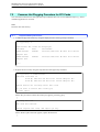
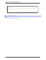
7.2 Common Hot Plugging Procedure for PCI Cards ................................................................................. 184
7.2.1 Replacement procedure .................................................................................................................. 184
7.2.2 Addition procedure .......................................................................................................................... 185
7.2.3 About removal ................................................................................................................................. 186
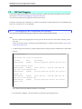
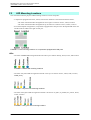
7.3 NIC Hot Plugging .................................................................................................................................. 187
7.3.1 Hot plugging a NIC incorporated into teaming ................................................................................ 187
7.3.2 Hot plugging a non-redundant NIC .................................................................................................. 192
7.3.3 NIC addition procedure .................................................................................................................... 194
7.4 FC Card Hot Plugging ........................................................................................................................... 195
7.4.1 Hot plugging an FC card incorporated with the ETERNUS multipath driver ................................... 195
7.4.2 FC card addition procedure ............................................................................................................. 199
7.5 Hot Replacement Procedure for iSCSI ................................................................................................. 200
7.5.1 Confirming the incorporation of a card with MPD ............................................................................ 200
xvi
C122-E108-10EN
PRIMEQUEST 1000 Series Administration Manual
Contents
7.5.2 Disconnecting MPD ......................................................................................................................... 212
7.5.3 Incorporating a card with MPD ........................................................................................................ 215
CHAPTER 8 Backup and Restore ................................................................................................................. 217
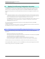
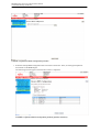
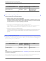
8.1 Backing Up and Restoring Configuration Information ........................................................................... 218
8.1.1 Backing up and restoring UEFI configuration information ............................................................... 218
8.1.2 Backing up and restoring MMB configuration information ............................................................... 221
8.1.3 Saving PSA management information ............................................................................................ 222
CHAPTER 9 System Startup, Shutdown, and Power Control ....................................................................... 223
9.1 Powering On/Off the Whole System ..................................................................................................... 224
9.2 Powering On and Off Partitions ............................................................................................................ 225
9.2.1 Powering on a partition .................................................................................................................... 225
9.2.2 Partition power-on unit ..................................................................................................................... 225
9.2.3 Powering off a partition .................................................................................................................... 226
9.2.4 Partition power-off unit ..................................................................................................................... 226
9.2.5 Partition power-on and power-off procedures ................................................................................. 227
9.2.6 Powering on a partition by using the MMB ...................................................................................... 227
9.2.7 Controlling partition startup by using the MMB ................................................................................ 228
9.2.8 Checking the partition power status by using the MMB .................................................................. 229
9.2.9 Powering off a partition by using the MMB ...................................................................................... 230
9.3 Scheduled Operations .......................................................................................................................... 232
9.3.1 Powering on a partition by a scheduled operation .......................................................................... 232
9.3.2 Powering off a partition by a scheduled operation .......................................................................... 232
9.3.3 Relationship between scheduled operations and the power recovery function ............................... 232
9.3.4 Scheduled operation support conditions ......................................................................................... 233
9.4 Automatic Partition Restart Conditions ................................................................................................. 235
9.4.1 Setting automatic partition restart conditions .................................................................................. 235
9.5 Power Failure and Power Recovery ..................................................................................................... 237
9.5.1 Settings in case of power failure ...................................................................................................... 237
9.5.2 Settings for power recovery ............................................................................................................. 237
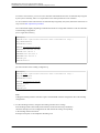
9.6 Remote Shutdown (Windows) .............................................................................................................. 238
9.6.1 Prerequisites for remote shutdown .................................................................................................. 238
9.6.2 How to use remote shutdown .......................................................................................................... 238
CHAPTER 10 Configuration and Status Checking (Contents, Methods, and Procedures) ........................... 241
10.1 MMB Web-UI ...................................................................................................................................... 242
10.2 MMB CLI ............................................................................................................................................. 245
10.3 PSA Web-UI ....................................................................................................................................... 246
10.4 PSA CLI .............................................................................................................................................. 247
10.5 UEFI .................................................................................................................................................... 248
10.6 ServerView Suite ................................................................................................................................ 249
CHAPTER 11 Error Notification and Maintenance (Contents, Methods, and Procedures) ........................... 251
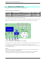
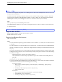
11.1 Maintenance ....................................................................................................................................... 252
11.1.1 Maintenance using the MMB ......................................................................................................... 252
11.1.2 Maintenance using PSA ................................................................................................................ 252
11.1.3 Maintenance method ..................................................................................................................... 258
11.1.4 Maintenance modes ...................................................................................................................... 258
11.1.5 Maintenance of the IOB and GSPB ............................................................................................... 260
11.1.6 Maintenance policy/preventive maintenance ................................................................................ 260
11.1.7 REMCS service overview .............................................................................................................. 260
11.1.8 REMCS linkage ............................................................................................................................. 261
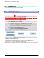
11.2 Troubleshooting .................................................................................................................................. 263
11.2.1 Troubleshooting overview .............................................................................................................. 263
11.2.2 Items to confirm before contacting a sales representative ............................................................ 265
11.2.3 Sales representative (contact) ....................................................................................................... 265
11.2.4 Finding out about abnormal conditions ......................................................................................... 265
11.2.5 Investigating abnormal conditions ................................................................................................. 269
xvii
C122-E108-10EN
PRIMEQUEST 1000 Series Administration Manual
Contents
11.2.6 Checking into errors in detail ......................................................................................................... 273
11.2.7 Problems related to the main unit or a PCI_Box ........................................................................... 273
11.2.8 MMB-related problems .................................................................................................................. 274
11.2.9 PSA-related problems ................................................................................................................... 274
11.2.10 SVmco-related problems ............................................................................................................. 275
11.2.11 Problems with partition operations .............................................................................................. 275
11.3 Notes on Troubleshooting ................................................................................................................... 277
11.4 Collecting Maintenance Data .............................................................................................................. 278
11.4.1 Logs that can be collected by the MMB ........................................................................................ 278
11.4.2 Logs that can be collected by PSA ................................................................................................ 283
11.4.3 Collecting data for investigation (Windows) .................................................................................. 285
11.4.4 Setting up the dump environment (Windows) ............................................................................... 285
11.4.5 Acquiring data for investigation (RHEL) ........................................................................................ 295
11.5 Configuring and Checking Log Information ........................................................................................ 296
11.5.1 List of log information .................................................................................................................... 296
11.6 Firmware Updates .............................................................................................................................. 297
11.6.1 Notes on updating firmware ........................................................................................................... 297
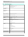
APPENDIX A Functions Provided by the PRIMEQUEST 1000 Series .......................................................... 299
A.1 Function List ......................................................................................................................................... 300
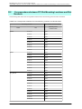
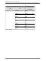
A.2 Correspondence between Functions and Interfaces ............................................................................ 305
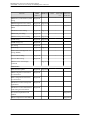
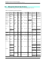
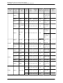
A.3 Management Network Specifications ................................................................................................... 309
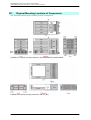
APPENDIX B Physical Mounting Locations and Port Numbers ..................................................................... 311
B.1 Physical Mounting Locations of Components ...................................................................................... 312
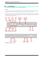
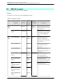
B.2 Port Numbers ....................................................................................................................................... 313
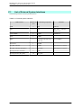
APPENDIX C Lists of External Interfaces ...................................................................................................... 315
C.1 List of External System Interfaces ........................................................................................................ 316
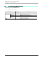
C.2 List of External MMB Interfaces ........................................................................................................... 317
C.3 List of Other External Interfaces ........................................................................................................... 318
APPENDIX D Physical Locations and BUS Numbers of Built-in I/O, and PCI Slot Mounting Locations and Slot
Numbers .............................................................................................................................................. 319
D.1 Physical Locations and BUS Numbers of Internal I/O Controllers of the PRIMEQUEST 1000 Series ....
320
D.2 Correspondence between PCI Slot Mounting Locations and Slot Numbers ........................................ 321
APPENDIX E PRIMEQUEST 1000 Series Cabinets (Link) ........................................................................... 323
APPENDIX F Status Checks with LEDs ........................................................................................................ 324
F.1 LED Types ............................................................................................................................................ 325
F.1.1 Power LED, Alarm LED, and Location LED .................................................................................... 325
F.1.2 Home LED ....................................................................................................................................... 325
F.1.3 LAN ................................................................................................................................................ 326
F.1.4 HDD ................................................................................................................................................ 326
F.1.5 PCI Express card slot ..................................................................................................................... 327
F.1.6 DVDB .............................................................................................................................................. 327
F.1.7 MMB ............................................................................................................................................... 328
F.1.8 PSU ................................................................................................................................................ 329
F.1.9 IO_PSU .......................................................................................................................................... 329
F.2 LED Mounting Locations ...................................................................................................................... 331
F.3 LED list ................................................................................................................................................. 332
APPENDIX G Component Mounting Conditions ............................................................................................ 337
G.1 CPU ..................................................................................................................................................... 338
G.2 DIMM ................................................................................................................................................... 340
G.2.1 DIMM mounting sequence .............................................................................................................. 341
G.2.2 DIMM mounting patterns ................................................................................................................ 342
G.3 PCI Card Mounting Conditions and Available Internal I/O ................................................................... 347
xviii
C122-E108-10EN
PRIMEQUEST 1000 Series Administration Manual
Contents
G.3.1 Available internal I/O ports .............................................................................................................. 347
G.4 Legacy BIOS Compatibility (CSM) ....................................................................................................... 348
G.5 Rack Mounting ..................................................................................................................................... 349
G.6 Installation Environment ....................................................................................................................... 350
G.7 SAS array disk unit ............................................................................................................................... 351
G.8 NIC (Network Interface Card) ............................................................................................................... 352
APPENDIX H Tree Structure of the MIB Provided with the PRIMEQUEST 1000 Series .............................. 353
H.1 MIB Tree Structure ............................................................................................................................... 354
H.2 MIB File Contents .................................................................................................................................. 356
APPENDIX I Windows Shutdown Settings .................................................................................................... 359
I.1 Shutdown from MMB Web-UI ................................................................................................................ 360
APPENDIX J Systemwalker Centric Manager Linkage ................................................................................. 361
J.1 Preparation for Systemwalker Centric Manager Linkage ...................................................................... 362
J.2 Configuring Systemwalker Centric Manager linkage ............................................................................ 363
J.2.1 MMB node registration ..................................................................................................................... 363
J.2.2 SNMP trap linkage ........................................................................................................................... 364
J.2.3 Event monitoring linkage ................................................................................................................. 366
J.2.4 GUI linkage ...................................................................................................................................... 367
J.2.5 Rack grouping function linkage ....................................................................................................... 367
J.2.6 Linkage with ServerView ................................................................................................................. 368
APPENDIX K How to Confirm Firmware of SAS Array Controller Card ......................................................... 369
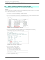
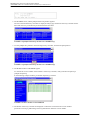
K.1 How to Confirm Firmware Version of WebBIOS ................................................................................... 370
K.2 How to confirm with ServerView RAID .................................................................................................. 373
APPENDIX L Software (Link) .......................................................................................................................... 375
APPENDIX M Failure Report Sheet ............................................................................................................... 376
M.1 Failure Report Sheet ............................................................................................................................ 377
Index ............................................................................................................................................................... 379
xix
C122-E108-10EN
PRIMEQUEST 1000 Series Administration Manual
Figures
Figures
Warning label location (PRIMEQUEST 1800E2/1800E rear) ............................................................................. x
Warning label location (PRIMEQUEST 1800E2/1800E rear) (IOBs removed) .................................................. xi
Warning label location (PCI_Box) ...................................................................................................................... xi
FIGURE 1.1 External network configuration ...................................................................................................... 2
FIGURE 1.2 External network functions ............................................................................................................ 3
FIGURE 1.3 Management LAN configuration .................................................................................................... 9
FIGURE 1.4 Maintenance LAN and REMCS LAN of the MMB ....................................................................... 16
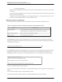
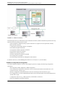
FIGURE 1.5 Connection configuration for video redirection ............................................................................ 21
FIGURE 1.6 Operating sequence of video redirection ..................................................................................... 21
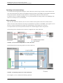
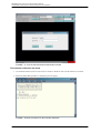
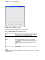
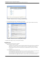
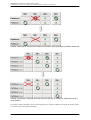
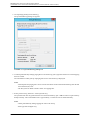
FIGURE 1.7 [Video Redirection] window in SA11071 or earlier and SB11062 or earlier ................................ 22
FIGURE 1.8 [Video Redirection] window in SA11081 or later and SB11071 or later ...................................... 23
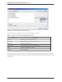
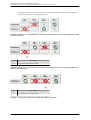
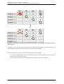
FIGURE 1.9 Selecting Full control mode/View only mode ............................................................................... 27
FIGURE 1.10 Case where another user has already established a video redirection connection .................. 27
FIGURE 1.11 Case where the user who established the later connection selects Full control mode ............. 28
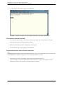
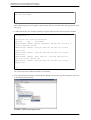
FIGURE 1.12 Changing the password for text console redirection (telnet connection) ................................... 29
FIGURE 1.13 Changing the password for text console redirection (input) ...................................................... 30
FIGURE 1.14 Connection diagram of text console redirection ........................................................................ 30
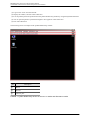
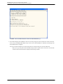
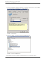
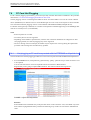
FIGURE 1.15 [Text Console Redirection] window ........................................................................................... 31
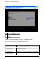
FIGURE 1.16 [Command] pull-down menu ..................................................................................................... 32
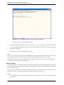
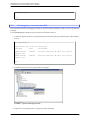
FIGURE 1.17 Text console redirection authentication window ........................................................................ 33
FIGURE 1.18 telnet connection for text console redirection ............................................................................ 33
FIGURE 1.19 telnet connection for text console redirection (connection established) .................................... 34
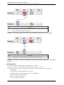
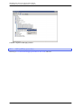
FIGURE 1.20 Forced disconnection of text console redirection (1) ................................................................. 35
FIGURE 1.21 Forced disconnection of text console redirection (2) ................................................................. 36
FIGURE 1.22 Connection configuration for remote storage ............................................................................ 37
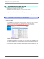
FIGURE 1.23 Window with a remote storage list ............................................................................................. 38
FIGURE 1.24 Remote storage selection window ............................................................................................. 39
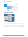
FIGURE 1.25 Window with a remote storage list ............................................................................................. 40
FIGURE 1.26 USB 2.0/USB 1.1 selection dialog box ...................................................................................... 41
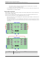
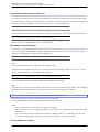
FIGURE 3.1 Examples of partition configurations in the PRIMEQUEST 1800E2/1800E ................................ 46
FIGURE 3.2 Example of operation where the SB in a test partition is a Reserved SB .................................... 48
FIGURE 3.3 BlueScreenTimeout setting ([Configuration] tab) ........................................................................ 51
FIGURE 3.4 BlueScreenTimeout setting ([Misc] settings) ............................................................................... 51
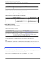
FIGURE 3.5 Example 1-a: Example with two SBs set as Reserved SBs in two partitions (SB#0 and SB#1 fail
simultaneously) ..................................................................................................................................... 52
FIGURE 3.6 Example 1-b: Example with one SB set as the Reserved SB in two partitions (SB#0 and SB#2 fail
simultaneously) ..................................................................................................................................... 52
FIGURE 3.7 Example 2: Example of multiple SBs failing in a partition ........................................................... 52
FIGURE 3.8 Example 3: Example with multiple free SBs (#2 and #3) set as Reserved SBs for Partition#0 ....
53
FIGURE 3.9 Example 4: Example where the Reserved SBs (#0, #1, and #2) for Partition#0 belong to other
partitions ................................................................................................................................................ 53
FIGURE 3.10 Example 5: Example where the Reserved SBs (#1, #2, and #3) for Partition#0 belong to other
partitions ................................................................................................................................................ 54
FIGURE 3.11 Example 6: Example with SB#0 set as a Reserved SB (when the Home SB fails) ................... 55
FIGURE 3.12 Example 7: Example with SB#0 set as a Reserved SB (when an SB other than the Home SB fails)
................................................................................................................................................................ 55
FIGURE 3.13 Mirroring within CPU and Mirroring between CPUs .................................................................. 59
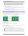
FIGURE 5.1 [Fibre Channel] window (example) ............................................................................................ 108
FIGURE 5.2 Single NIC interface and bonding configuration interface ......................................................... 109
FIGURE 5.3 Required interface recovery example 1 ..................................................................................... 115
FIGURE 5.4 Required interface recovery example 2 ..................................................................................... 115
FIGURE 5.5 Example of single NIC interface ................................................................................................ 120
FIGURE 5.6 Single NIC interface and bonding configuration interface ......................................................... 126
FIGURE 5.7 Single NIC interface and bonding configuration interface ......................................................... 137
FIGURE 6.1 [Fibre Channel] window (example) ............................................................................................ 150
xx
C122-E108-10EN
PRIMEQUEST 1000 Series Administration Manual
Figures
FIGURE 6.2 Single NIC interface and bonding configuration interface ......................................................... 151
FIGURE 6.3 Example of single NIC interface ................................................................................................ 162
FIGURE 6.4 Single NIC interface and bonding configuration interface ......................................................... 167
FIGURE 6.5 Single NIC interface and bonding configuration interface ......................................................... 175
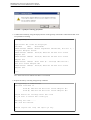
FIGURE 7.1 [Device Manager] window ......................................................................................................... 188
FIGURE 7.2 [Teaming] tab ............................................................................................................................ 188
FIGURE 7.3 [Adapter Teaming] properties .................................................................................................... 189
FIGURE 7.4 [Device Manager] window ......................................................................................................... 190
FIGURE 7.5 [Teaming] tab ............................................................................................................................ 191
FIGURE 7.6 [Device Manager] window ......................................................................................................... 191
FIGURE 7.7 [Device Manager] window ......................................................................................................... 192
FIGURE 7.8 [Device Manager] window ......................................................................................................... 194
FIGURE 7.9 [PCI Devices] window ................................................................................................................ 195
FIGURE 7.10 [Fibre Channel] window ........................................................................................................... 196
FIGURE 7.11 HBAnyware ............................................................................................................................. 196
FIGURE 7.12 ETERNUS Multipath Manager ................................................................................................ 197
FIGURE 7.13 ETERNUS Multipath Manager ................................................................................................ 199
FIGURE 7.14 [PCI Devices] window .............................................................................................................. 200
FIGURE 7.15 [Ethernet Controller] window ................................................................................................... 201
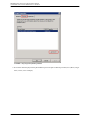
FIGURE 7.16 Starting [iSCSI Initiator] ........................................................................................................... 201
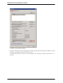
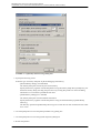
FIGURE 7.17 [iSCSI Initiator Properties] window (in Windows Server 2008) ................................................ 202
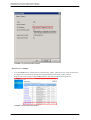
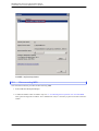
FIGURE 7.18 [Target Properties] window ...................................................................................................... 203
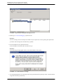
FIGURE 7.19 [Session Connections] window ................................................................................................ 204
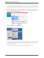
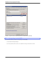
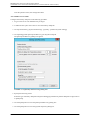
FIGURE 7.20 [Target Properties] window ...................................................................................................... 205
FIGURE 7.21 [Device Details] window .......................................................................................................... 206
FIGURE 7.22 [PCI Devices] window .............................................................................................................. 206
FIGURE 7.23 [Ethernet Controller] window ................................................................................................... 207
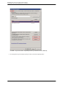
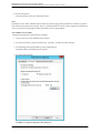
FIGURE 7.24 [iSCSI Initiator] ........................................................................................................................ 207
FIGURE 7.25 [iSCSI Initiator Properties] window (in Windows Server 2008 R2) .......................................... 208
FIGURE 7.26 [Properties] window ................................................................................................................. 209
FIGURE 7.27 [Multiple Connected Session (MCS)] window ......................................................................... 210
FIGURE 7.28 [iSCSI Initiator Properties] window (in Windows Server 2008 R2) .......................................... 211
FIGURE 7.29 [Devices] window ..................................................................................................................... 212
FIGURE 7.30 [ETERNUS Multipath Manager] window ................................................................................. 213
FIGURE 7.31 TCP/IP deletion message ........................................................................................................ 213
FIGURE 7.32 [iSCSI Initiator Properties] window (in Windows Server 2008) ................................................ 214
FIGURE 7.33 [iSCSI Initiator Properties] window (in Windows Server 2008 R2) .......................................... 215
FIGURE 7.34 ETERNUS Multipath Manager ................................................................................................ 216
FIGURE 8.1 [Backup BIOS Configuration] window ....................................................................................... 219
FIGURE 8.2 [Restore BIOS Configuration] window ....................................................................................... 220
FIGURE 8.3 [Restore BIOS Configuration] window (partition selection) ....................................................... 220
FIGURE 8.4 [Backup/Restore MMB Configuration] window .......................................................................... 221
FIGURE 8.5 Restore confirmation dialog box ................................................................................................ 222
FIGURE 9.1 [System Power Control] window ................................................................................................ 224
FIGURE 9.2 [Power Control] window ............................................................................................................. 228
FIGURE 9.3 [Power Control] window ............................................................................................................. 229
FIGURE 9.4 [Information] window ................................................................................................................. 230
FIGURE 9.5 [Power Control] window ............................................................................................................. 231
FIGURE 9.6 [ASR (Automatic Server Restart) Control] window .................................................................... 235
FIGURE 9.7 Simplified help for the shutdown command ............................................................................... 239
FIGURE 11.1 Web-UI functions ..................................................................................................................... 254
FIGURE 11.2 Operations management software linkage .............................................................................. 256
FIGURE 11.3 REMCS linkage ....................................................................................................................... 262
FIGURE 11.4 Troubleshooting overview ....................................................................................................... 263
FIGURE 11.5 Label location (1) ..................................................................................................................... 264
FIGURE 11.6 Label location (2) ..................................................................................................................... 265
FIGURE 11.7 Alarm LED on the front panel of the device ............................................................................. 266
FIGURE 11.8 System status display in the MMB Web-UI window ................................................................ 267
xxi
C122-E108-10EN
PRIMEQUEST 1000 Series Administration Manual
Figures
FIGURE 11.9 Alarm E-Mail settings window ................................................................................................. 268
FIGURE 11.10 System status display ............................................................................................................ 269
FIGURE 11.11 System event log display ....................................................................................................... 270
FIGURE 11.12 [Partition Configuration] window ............................................................................................ 271
FIGURE 11.13 [Partition Event Log] window ................................................................................................. 272
FIGURE 11.14 [Agent Log] window ............................................................................................................... 272
FIGURE 11.15 [System Event Log] window .................................................................................................. 279
FIGURE 11.16 [System Event Log Filtering Condition] window .................................................................... 280
FIGURE 11.17 [System Event Log (Detail)] window ...................................................................................... 282
FIGURE 11.18 [Agent Log] window ............................................................................................................... 284
FIGURE 11.19 [Startup and Recovery] dialog box ........................................................................................ 288
FIGURE 11.20 [Startup and Recovery] dialog box ......................................................................................... 289
FIGURE 11.21 Advanced options dialog box ................................................................................................ 291
FIGURE 11.22 [Virtual Memory] dialog box ................................................................................................... 292
FIGURE 11.23 [Advanced] tab of the dialog box ............................................................................................ 293
FIGURE 11.24 [Virtual Memory] dialog box .................................................................................................... 294
FIGURE B.1 Physical mounting locations in the PRIMEQUEST 1800E2/1800E .......................................... 312
FIGURE B.2 Physical mounting locations in the PCI_Box ............................................................................. 312
FIGURE B.3 GSPB port numbers .................................................................................................................. 313
FIGURE B.4 MMB port numbers ................................................................................................................... 313
FIGURE F.1 LED mounting locations on components equipped with LAN ports .......................................... 331
FIGURE F.2 MMB LED mounting locations ................................................................................................... 331
FIGURE F.3 System LED mounting locations ............................................................................................... 331
FIGURE F.4 PCI_Box LED mounting locations ............................................................................................. 331
FIGURE H.1 MIB tree structure ..................................................................................................................... 355
FIGURE K.1 drivers command in the UEFI shell ........................................................................................... 370
FIGURE K.2 dh command in the UEFI shell .................................................................................................. 370
FIGURE K.3 [Adapter Selection] window in the WebBIOS (1) ...................................................................... 371
FIGURE K.4 [Adapter Selection] window in the WebBIOS (2) ...................................................................... 371
FIGURE K.5 Home window in the WebBIOS ................................................................................................. 371
FIGURE K.6 [Controller Properties] window in the WebBIOS ....................................................................... 372
FIGURE K.7 [General] tab in the ServiewView RAID Manager ..................................................................... 373
xxii
C122-E108-10EN
PRIMEQUEST 1000 Series Administration Manual
Tables
Tables
TABLE 1.1 External network names and functions ............................................................................................ 2
TABLE 1.2 IP addresses for the PRIMEQUEST 1000 series server (IP addresses set from the MMB) ........... 4
TABLE 1.3 IP addresses for the PRIMEQUEST 1000 series server (set from the operating system in a partition)
.................................................................................................................................................................. 6
TABLE 1.4 Restrictions on the management LAN ............................................................................................. 9
TABLE 1.5 Parts of the management LAN configuration ................................................................................. 11
TABLE 1.6 Maintenance LAN/REMCS LAN .................................................................................................... 16
TABLE 1.7 Maximum number of connections using the remote operation function ........................................ 20
TABLE 1.8 [Video Redirection] window menus ............................................................................................... 23
TABLE 1.9 [Video Redirection] window buttons .............................................................................................. 25
TABLE 1.10 Video redirection functions .......................................................................................................... 26
TABLE 1.11 Connection persistence time ....................................................................................................... 28
TABLE 1.12 Commands in the [Text Console Redirection] window ................................................................ 32
TABLE 1.13 Buttons available in the remote storage list window .................................................................... 38
TABLE 1.14 Items in the remote storage selection window ............................................................................. 39
TABLE 1.15 Supported storage types ............................................................................................................. 40
TABLE 1.16 Buttons in the USB 2.0/USB 1.1 selection dialog box ................................................................. 41
TABLE 3.1 Partition configuration rules (components) .................................................................................... 45
TABLE 3.2 Notes on specific connections in switching to a Reserved SB ...................................................... 57
TABLE 3.3 Mirroring operations by model and configuration .......................................................................... 59
TABLE 3.4 Memory Mirror conditions .............................................................................................................. 59
TABLE 3.5 Replaceable components and replacement conditions ................................................................. 61
TABLE 3.6 Replacement notification messages of RAS Support Service (BBU) ............................................ 64
TABLE 3.7 Event log at recalibration ............................................................................................................... 65
TABLE 3.8 Event log when the battery level is low (1) .................................................................................... 66
TABLE 3.9 Event log when the battery level is low (2) .................................................................................... 66
TABLE 3.10 Replacement notification messages of RAS Support Service (UPS) .......................................... 66
TABLE 3.11 Expandability of components and addition conditions ................................................................. 72
TABLE 3.12 Component removal conditions ................................................................................................... 77
TABLE 3.13 Partition settings (before switching) ............................................................................................. 82
TABLE 3.14 Reserved SB settings (before switching) ..................................................................................... 82
TABLE 3.15 Partition status transitions ........................................................................................................... 83
TABLE 3.16 Explanation of partition status transitions .................................................................................... 83
TABLE 3.17 Partition settings (after switching) ................................................................................................ 83
TABLE 3.18 Reserved SB settings (after switching) ........................................................................................ 84
TABLE 6.1 Correspondence between bus addresses and interface names ................................................. 153
TABLE 6.2 Hardware address description examples .................................................................................... 154
TABLE 6.3 Example of interface information about the replacement NIC ..................................................... 157
TABLE 6.4 Example of entered values corresponding to the interface names before and after NIC replacement
.............................................................................................................................................................. 158
TABLE 6.5 Confirmation of interface names .................................................................................................. 160
TABLE 9.1 Power-on method and unit .......................................................................................................... 225
TABLE 9.2 Power-off methods and units ....................................................................................................... 226
TABLE 9.3 Power-on/off permissions ............................................................................................................ 227
TABLE 9.4 Relationship between scheduled operations and power recovery mode .................................... 232
TABLE 9.5 Power on/off ................................................................................................................................ 233
TABLE 9.6 Display and setting items in the [ASR Control] window ............................................................... 236
TABLE 9.7 Power recovery policy ................................................................................................................. 237
TABLE 10.1 Functions provided by the MMB Web-UI ................................................................................... 242
TABLE 10.2 Functions provided by the MMB CLI ......................................................................................... 245
TABLE 10.3 Functions provided by the PSA Web-UI .................................................................................... 246
TABLE 10.4 Functions provided by the PSA CLI ........................................................................................... 247
TABLE 10.5 Menus provided by the UEFI ..................................................................................................... 248
TABLE 11.1 Log file information .................................................................................................................... 255
TABLE 11.2 Operations that can be performed from the GUI of the partition ............................................... 257
TABLE 11.3 Information managed by partition ............................................................................................... 257
xxiii
C122-E108-10EN
PRIMEQUEST 1000 Series Administration Manual
Tables
TABLE 11.4 Maintenance modes .................................................................................................................. 259
TABLE 11.5 Maintenance mode functions ..................................................................................................... 259
TABLE 11.6 Icons indicating the system status ............................................................................................. 267
TABLE 11.7 System problems and memory dump collection ........................................................................ 278
TABLE 11.8 Setting and display items in the [System Event Log Filtering Condition] window ...................... 280
TABLE 11.9 Setting and display items in the [System Event Log (Detail)] window ....................................... 282
TABLE 11.10 Memory dump types and sizes ................................................................................................ 286
TABLE A.1 Functions ..................................................................................................................................... 300
TABLE A.2 Correspondence between functions and interfaces .................................................................... 305
TABLE A.3 Management network specifications ........................................................................................... 309
TABLE C.1 External system interfaces .......................................................................................................... 316
TABLE C.2 External MMB interfaces ............................................................................................................. 317
TABLE C.3 Other external interfaces ............................................................................................................. 318
TABLE D.1 Correspondence between physical locations of SB internal I/O controllers and BUS numbers ....
320
TABLE D.2 Correspondence between PCI Slot Mounting Locations and Slot Numbers ............................... 321
TABLE F.1 Power LED, Alarm LED, and Location LED ................................................................................ 325
TABLE F.2 SB Home LED ............................................................................................................................. 326
TABLE F.3 LAN LEDs .................................................................................................................................... 326
TABLE F.4 HDD LEDs ................................................................................................................................... 326
TABLE F.5 HDD status and LED display ....................................................................................................... 326
TABLE F.6 PCI Express card slot LEDs ........................................................................................................ 327
TABLE F.7 PCI Express card status and LED display ................................................................................... 327
TABLE F.8 DVDB LEDs ................................................................................................................................. 327
TABLE F.9 DVDB (device) status and LED display ....................................................................................... 328
TABLE F.10 MMB LEDs ................................................................................................................................ 328
TABLE F.11 MMB (device) status and LED display ...................................................................................... 329
TABLE F.12 PSU LED ................................................................................................................................... 329
TABLE F.13 Power status and PSU LED display .......................................................................................... 329
TABLE F.14 IO_PSU LEDs ........................................................................................................................... 330
TABLE F.15 Power status and IO_PSU LED display .................................................................................... 330
TABLE F.16 LEDs .......................................................................................................................................... 332
TABLE G.1 x2APIC support of each operating system (PRIMEQUEST 1800E2) ......................................... 338
TABLE G.2 Numbers of SBs and CPUs per partition .................................................................................... 339
TABLE G.3 Relationship between DIMM size and mutual operability (within an SB) .................................... 340
TABLE G.4 Relationship between DIMM size and mutual operability (within a partition) .............................. 340
TABLE G.5 Relationship between DIMM size and mutual operability (within a cabinet) ............................... 341
TABLE G.6 Identical DIMM groups ................................................................................................................ 341
TABLE G.7 Mounting sequence of DIMMs where a single CPU is mounted on an SB ................................. 342
TABLE G.8 Mounting sequence of DIMMs where two CPUs are mounted on an SB ................................... 342
TABLE G.9 DIMM mounting pattern .............................................................................................................. 342
TABLE G.10 DIMM mounting pattern 1 ......................................................................................................... 343
TABLE G.11 DIMM mounting pattern 2 ......................................................................................................... 343
TABLE G.12 DIMM mounting pattern 3 ......................................................................................................... 344
TABLE G.13 DIMM mounting pattern 4 ......................................................................................................... 345
TABLE G.14 Available internal I/O ports and the quantities .......................................................................... 347
TABLE H.1 MIB file contents
................................................................................................. 356
TABLE J.1 Files and tools to prepare ............................................................................................................ 362
xxiv
C122-E108-10EN
CHAPTER 1
Network Environment
Setup and Tool
Installation
This chapter describes the external network environment and
management tool installation for the PRIMEQUEST 1000 series.
For an overview of the management tools used for the PRIMEQUEST
1000 series, see Chapter 8 Operations Management Tools in the
PRIMEQUEST 1000 Series General Description (C122-B022EN).
1.1 External Network Configuration ................................... 2
1.2 How to Configure the External Networks (Management
LAN/Maintenance LAN/Production LAN) ................ 4
1.3 Management LAN ........................................................ 8
1.4 Maintenance LAN/REMCS LAN ................................. 16
1.5 Production LAN .......................................................... 17
1.6 Management Tool Operating Conditions and Use ....
18
PRIMEQUEST 1000 Series Administration Manual
CHAPTER 1 Network Environment Setup and Tool Installation
1.1
External Network Configuration
The following diagram shows the external network configuration for the PRIMEQUEST 1000 series.
No.
Description
(1)
SW redundancy
(2)
Redundancy by teaming (GLS or equivalent)
(3)
Disabled on the standby side
FIGURE 1.1 External network configuration
The following table lists the external networks. The letters A, B, and C correspond to those in FIGURE 1.1 External
network configuration.
TABLE 1.1 External network names and functions
Letter
A
External network name
Management LAN
Function
-
2
MMB Web-UI/CLI operations
Operations management server
Text console redirection
Video redirection
PRIMECLUSTER linkage
C122-E108-10EN
PRIMEQUEST 1000 Series Administration Manual
CHAPTER 1 Network Environment Setup and Tool Installation
Letter
External network name
Function
- Systemwalker linkage
- ServerView linkage
- REMCS connection
B
Maintenance LAN
C
Operation LAN (production LAN)
- FST (CE terminal) connection
- REMCS connection
For job operations
The following diagram shows the functions of external networks for the PRIMEQUEST 1000 series.
FIGURE 1.2 External network functions
3
C122-E108-10EN
PRIMEQUEST 1000 Series Administration Manual
CHAPTER 1 Network Environment Setup and Tool Installation
1.2
How to Configure the External Networks (Management LAN/
Maintenance LAN/Production LAN)
The PRIMEQUEST 1000 series server must be connected to the following three types of external networks. The
respective external networks are dedicated to security and load distribution. (See FIGURE 1.1 External network
configuration.)
- Management LAN
- Maintenance LAN
- Production LAN
Note
You can connect the management LAN and production LAN to the same subnet, but you need to connect the
maintenance LAN to another subnet.
This section describes the IP addresses for the PRIMEQUEST 1000 series server.
1.2.1
IP addresses used in the PRIMEQUEST 1000 series server
Each of the SB, GSPB, and MMB units in the PRIMEQUEST 1000 series server have network interfaces. Each
port of these network interfaces must be assigned an IP address.
To the ports, assign IP addresses appropriate to the external network environment of the PRIMEQUEST 1000 series
server.
The following describes the IP addresses assigned to the ports.
TABLE 1.2 IP addresses for the PRIMEQUEST 1000 series server (IP addresses set from the MMB) lists the IP
addresses that are set from the MMB. TABLE 1.3 IP addresses for the PRIMEQUEST 1000 series server (set from
the operating system in a partition) lists the IP addresses that are set from the operating system.
The IP addresses in TABLE 1.2 IP addresses for the PRIMEQUEST 1000 series server (IP addresses set from the
MMB) are assigned to the NICs (network interface controllers) on the MMBs. Each NIC is connected to an SB or
an external network port of the MMB through the switching hub on the MMB. The MMB firmware uses the IP
addresses.
The standard configuration has one MMB. For a dual MMB configuration, which has two MMBs, assign a common
virtual IP address to both MMBs. In addition to the virtual IP address, assign one physical IP address to each MMB.
TABLE 1.2 IP addresses for the PRIMEQUEST 1000 series server (IP addresses set from the MMB)
Name
NIC
Type
IP address
setting
method
Description
- Management LAN IP address: MMB Virtual/Physical IP address
This IP address is used for communication when the MMB is connected to the management LAN.
The physical IP address is assigned to the NIC of the user port of each MMB, and the virtual IP address
is assigned commonly to the duplicated MMBs. The virtual IP address is used for access from a PC
etc. on the management LAN. The virtual IP is inherited by an active MMB.
4
C122-E108-10EN
PRIMEQUEST 1000 Series Administration Manual
CHAPTER 1 Network Environment Setup and Tool Installation
Name
NIC
Type
Virtual IP
address
IP address
setting
method
Description
Virtual IP
Address
MMB
(common)
(*1)
Set it from
the MMB
CLI or MMB
Web-UI.
The PC connected to the management LAN
uses this IP address to communicate (via the
Web, telnet, etc.) with the (active) MMB.
The PC user need not be aware of which
MMB is active, MMB#0 or MMB#1.
MMB#0 IP
Address
MMB#0 (*1) Physical
Set it from
The PC connected to the management LAN
IP address the MMB
uses this IP address to communicate with
CLI or MMB MMB#0. (*2)
Web-UI.
MMB#1 IP
Address
MMB#1 (*1) Physical
Set it from
The PC connected to the management LAN
IP address the MMB
uses this IP address to communicate with
CLI or MMB MMB#1. (*2)
Web-UI.
- Maintenance LAN IP address: Maintenance IP address
This IP address is used for communication when the MMB is connected to the maintenance LAN.
Maintenance MMB
IP Address (common)
Physical IP Set it from
address
the MMB
(*3)
CLI or MMB
Web-UI.
This IP address is used for communication
with REMCS, without using the
management LAN. The MMB also uses the
IP address to communicate with the
maintenance terminal connected to the CE
port.
- MMB-PSA LAN IP address: MMB-PSA IP Address
This is a dedicated IP address for MMB communication with PSA (on the PRIMEQUEST 1800E)
or SVS (on the PRIMEQUEST 1800E2) running on the operating system in each partition.
MMB-PSA
IP Address
MMB
(common)
(*4)
Physical IP Set it from
address
the MMB
(*3)
Web-UI.
This is a dedicated IP address for
communication with PSA (on the
PRIMEQUEST 1800E) or SVS (on the
PRIMEQUEST 1800E2) running on the
operating system in each partition.
- Console redirection IP address: Console Redirection IP Address
Console
Redirection
IP Address
BMC
Physical IP Set it from
address
the MMB
(*5)
Web-UI.
This IP address is used to access the console
redirection function in each partition from
the PC on the management LAN. An IP
address on the management LAN is
assigned to each partition.
*1
These three addresses must have the same subnet address.
*2
The server administrator need not be concerned with the individual IP addresses specified for
communication.
5
C122-E108-10EN
PRIMEQUEST 1000 Series Administration Manual
CHAPTER 1 Network Environment Setup and Tool Installation
*3
The IP address is intended only for communication with the active MMB.
*4
It is connected to the PSA-to-MMB communication LAN inside the cabinet, and it is not connected to
any external network. The assigned IP address must be in a different subnet from the management
LAN, maintenance LAN, or production LAN. The default setting is 172.30.0.1/24, and it does not have
to be changed unless it is in conflict with another subnet.
*5
This IP address is to access the console redirection function provided by BMC. It accesses BMC from
the user port on the management LAN of MMB via the dedicated network for BMC-to-MMB
communication inside the cabinet.
MMB changes the local IP address of BMC to the IP address on the management LAN by NAT. From
the PC on the management LAN, the console redirection function of BMC is used via MMB.
*6
If Disable is set for this address, the PSA Web-UI cannot be viewed. Also, neither REMCS notification
nor e-mail notification related to PSA (on the PRIMEQUEST 1800E) or SVS (on the PRIMEQUEST
1800E2) is sent.
A separate subnet must be assigned to "1. Management LAN", "2. Maintenance LAN" (external network), and "3.
MMB-PSA LAN" (inside the cabinet LAN).
Because "3. MMB-PSA LAN" is closed to the outside of the cabinet, the same subnet as that for "3.MMB-PSA
LAN" in another cabinet can be used.
For the IP address to be assigned to "4. Console redirection", the same subnet as that assigned to "1. Management
LAN" must be used.
Remarks
MMB uses the following subnets permanently for internal communication.
The following subnets cannot be specified:
127.1.1.0/24
127.1.2.0/24
127.1.3.0/24
The ICH (I/O controller hub) on an SB in each partition has a 100 Mb Ethernet port connected with the PSA-toMMB communication LAN inside the cabinet. The operating system assigns the IP address of the 100 Mb Ethernet
port.
TABLE 1.3 IP addresses for the PRIMEQUEST 1000 series server (set from the operating system in a
partition)
LAN port
IP address setting
method
Description
100 MbE port on
Set it from the OS in 100 MbE port connected to the PSA-to-MMB LAN inside
SB (NIC in ICH) (*1) each partition.
the cabinet. This IP address and the IP address of the MMBPSA IP Address in TABLE 1.2 IP addresses for the
PRIMEQUEST 1000 series server (IP addresses set from
the MMB) IP addresses for the PRIMEQUEST 1000 series
server (IP addresses set from the MMB) are in the same
subnet. An IP address must be assigned to each partition.
6
C122-E108-10EN
PRIMEQUEST 1000 Series Administration Manual
CHAPTER 1 Network Environment Setup and Tool Installation
LAN port
GbE port in GSPB
IP address setting
method
Description
Set it from the OS in This depends on the partition configuration. The number of
each partition.
LGSPBs (0 to 4) in the configuration is multiplied by 4.
Network card
Set it from the OS in Each port is connected to a network outside the cabinet. The
mounted in PCI
each partition.
ports in the relevant partition must have IP addresses.
Express slot in IOB or
(Assign IP addresses to the ports used for actual operation.)
PCI_Box.
*1
The default IP address (172.30.0.[partition number + 2]) is assigned during installation of PSA + SVS
(on the PRIMEQUEST 1800E) or SVS (on the PRIMEQUEST 1800E2). The default IP address can
be used unless it is in conflict with the one in the other subnet.
For details on the partition number, see 1.3.4 [Partition Configuration] window in the PRIMEQUEST
1000 Series Tool Reference (C122-E110EN).
If it is in conflict with the one in the other subnet, change it manually. For details on the setting
procedure, see the PRIMEQUEST 1000 Series Installation Manual (C122-E107EN).
Remarks
For NIC on the partition side of PSA-MMB LAN, use NIC in ICH on the Home SB. The network
device name is not defined uniquely. It is searched in NIC in ICH on the Home SB by using the bus
number, device number, and function number assigned to NIC.
Because the Reserved SB function keeps the communication between the PSA and MMB even if the
Home SB is switched, the MMB writes over the MAC address of the NIC in ICH on the Home SB and
keeps the same MAC address as that before the SB was switched.
For this MAC address, a unique value is assigned to each partition and managed as system FRU
information so that it is unique per cabinet.
7
C122-E108-10EN
PRIMEQUEST 1000 Series Administration Manual
CHAPTER 1 Network Environment Setup and Tool Installation
1.3
Management LAN
This section describes the configuration of the management LAN for the PRIMEQUEST 1000 series.
1.3.1
Overview of the management LAN
The MMB has two GbE LAN ports (USER ports) dedicated to the management LAN.
The partition side can use the GbE LAN port on the GSPB as a management LAN port. The PCL communications/
operations management server is connected to the MMB USER port through an external switch.
IP addresses of the management LAN (MMB)
Each MMB has one physical IP address for the management interface of the PRIMEQUEST 1000 series server. In
addition to that, the primary MMB shares a common virtual IP address in the system. You can set these IP addresses
from the MMB Web-UI or CLI.
Remarks
Virtual LAN interfaces are used for the management LAN interfaces. The physical LAN interfaces are used only
for recognizing the respective MMBs.
The physical LAN interface of each MMB makes redundant the two User ports located in that MMB, using the
interface redundancy function, to create a single LAN interface.
Virtual LAN interfaces handle the common virtual IP address shared between the two redundant MMBs. The Virtual
LAN interfaces share the physical LAN interfaces, which are ports on the two MMBs. The ports are treated as valid
channels on the active MMB. Any switching of the active MMB causes switching of the corresponding connections
to Virtual LAN channels.
The following shows a management LAN configuration diagram. The IP addresses are examples. The addresses
depend on the settings.
8
C122-E108-10EN
PRIMEQUEST 1000 Series Administration Manual
CHAPTER 1 Network Environment Setup and Tool Installation
No.
Description
(1)
Physical LAN IP example (MMB #0): 10.20.30.101
(2)
Physical LAN IP example (MMB #1): 10.20.30.102
(3)
Virtual LAN IP example: 10.20.30.100
FIGURE 1.3 Management LAN configuration
If either USER port fails, the interface redundancy function switches to the other port in the MMB to ensure
continuous service. If a failure occurs in the active MMB itself, the Virtual LAN channels become unusable. Then,
the standby MMB inherits the virtual IP address from the active MMB to ensure continuous service.
The following interfaces are available with a configured management LAN:
Interfaces available to the system administrator:
- Web-UI interface using HTTP/HTTPS
- CLI interface via telnet/SSH
- Partition and console operations through the video redirection function
Interface available to system management software:
- RMCP and RMCP + interface
Remarks
The restrictions on management LAN interfaces other than Virtual LAN channels are described below.
TABLE 1.4 Restrictions on the management LAN
Channel name
RMCP connection Web-UI connection
(UDP)
(http/https)
CLI connection
(telnet/ssh)
Virtual LAN channel
Possible
Possible
Possible
Physical LAN channel (Active MMB)
Possible
Not possible
Possible
Possible with
restrictions (*1)(*2)
Not possible
Possible with
restrictions (*3)
Physical LAN channel (Standby MMB)
*1 The connection cannot send or receive data of over 4 Kbytes.
*2 The connection sends data to the active MMB, so adequate performance cannot be obtained.
*3 Only the following commands can be executed:
- Set command
set active_mmb 0
- Show commands
show active_mmb
show access_control
show date
show timezone
show gateway
show http
9
C122-E108-10EN
PRIMEQUEST 1000 Series Administration Manual
CHAPTER 1 Network Environment Setup and Tool Installation
show http_port
show https
show https_port
show ssh
show ssh_port
show telnet
show telnet_port
show ip
show network
show exit_code
ping
who
netck arptbl
netck arping
netck ifconfig
netck stat
show user_list
help
show snmp sys_location
show snmp sys_contact
show snmp community
show snmp trap
show maintenance_ip
IP address of the management LAN (partition)
To the partition side, an IP address of the management LAN must be assigned to communicate with PSA running
on the operating system or SVS from the terminal, etc. on the management LAN. The IP address is assigned to the
GbE port on the GSPB, the IOB, or the PCI_Box mounted on the network card. Also, for monitoring with SVOM,
an IP address must be assigned to the management LAN.
When it is linked with PRIMECLUSTER, the PSA (on the PRIMEQUEST 1800E) or SVS (on the PRIMEQUEST
1800E2) on the partition side communicates with the user port of the MMB via the management LAN. It also
provides the function for monitoring the status of the cluster node and the node switching function.
1.3.2
How to configure the management LAN
The network for MMB access from external terminals is the management LAN. The MMB has three types of
network port: USER port (duplicated) used for management, CE port used for maintenance, and REMCS port used
for remote maintenance.
The REMCS port and CE port are connected to one NIC through a switching hub. The PSA-to-MMB network in
the PRIMEQUEST 1000 series server is a dedicated LAN.
For management LAN-related settings for MMB access, use the CLI or the [Network Configuration] menu in the
Web-UI.
For details on the network configuration, see 1.1 External Network Configuration.
10
C122-E108-10EN
PRIMEQUEST 1000 Series Administration Manual
CHAPTER 1 Network Environment Setup and Tool Installation
The following lists the settings for the management LAN configuration. Only a user with Administrator privileges
can make management LAN-related settings.
For details on the setting window, see Chapter 1 MMB Web-UI (Web User Interface) Operations in the
PRIMEQUEST 1000 Series Tool Reference (c122-E110EN).
TABLE 1.5 Parts of the management LAN configuration
Display/Setting item
Description
Network Interface: IP address and other settings for MMB access
Virtual IP Address
Virtual IP address. In a dual MMB configuration, the IP address is inherited
during MMB switching.
Host Name/IP Address/Subnet Mask/Gateway Address
MMB#0 (MMB#1) IP Address
Physical IP address of MMB#0 (MMB#1). You set this IP address for MMB#0
(MMB#1) mounted in the system.
Enable/Disable setting
Interface Name/IP Address/Subnet Mask/Gateway Address
DNS (optional)
Option. It specifies the IP address of the DNS server used. The default is Disable.
Enable/Disable setting
IP Address: DNS Server 1/DNS Server 2/DNS Server 3
Management LAN
Specifies duplication of the management LAN ports. The default is Disable.
(Only the ports on the #0 side are enabled.)
Enable/Disable setting
Maintenance IP Address
Specifies the REMCS/CE port. The default is Disable.
Enable/Disable setting
IP Address/Subnet Mask/SMTP Address
MMB-PSA IP Address
IP Address/Subnet Mask/Gateway Address
Specifies the NIC on the MMB of the PSA-to-MMB LAN. The default is Enable
and the specified [IP Address] value. The MMB blocks communication between
partitions.
Management LAN Port Configuration: Management LAN port settings
Speed/Duplex for MMB#0
(MMB#1)
Specifies a Speed/Duplex value for the MMB#0 (MMB#1) LAN ports.
Port: USER Port, Maintenance Port
Setting value: Auto (default), 1G/Full, 100M/Full, 100M/Half, 10M/Full, 10M/
Half
The MMB USER port is duplicated.
The speed of 1 Gbps can be specified only for the USER ports. The possible
settings for the respective ports depend on the MMB hardware configuration.
Network Protocols: Network protocol settings
HTTP, HTTPS, telnet, SSH,
SNMP
Specifies whether to enable or disable a protocol, the port number, and the
Timeout time.
SNMP Configuration: SNMP-related settings
11
C122-E108-10EN
PRIMEQUEST 1000 Series Administration Manual
CHAPTER 1 Network Environment Setup and Tool Installation
Display/Setting item
Description
SNMP Community
Specifies SNMP System Information and Community/User values.
- System Information: Specifies System Location and System Contact
values for SNMP. It also displays the system name specified from
[System] - [System Information].
- Community: Can specify up to 16 Community/User items. Each
Community/User item includes the access-permitted IP address, SNMP
version, access permission, and authentication settings. For settings
specific to SNMP v3, use the SNMP v3 Configuration menu.
SNMP Trap
Specifies SNMP trap destinations.
- You can set up to 16 destinations. Each trap destination item includes the
Community/User name, destination IP address, SNMP version, and
authentication level settings.
- [Test Trap] button: Sends a test trap to the specified trap destination.
SNMP v3 Configuration: Settings specific to SNMP v3
Engine ID
Specifies the Engine ID.
- Enter the encryption hash function, authentication passphrase, and
encryption passphrase for users.
SSL: SSL settings
Create CSR
Creates a private key and a request for a signature (CSR: Certificate Signing
Request)
- SSL certificate status: Displays the current status of SSL certificate
installation.
- Key length: Length of the private key, 1024 bits or 2048 bits
- Entered information on the owner specified for the CSR
- Country, prefecture, city/town, organization, department, server, e-mail
address
- [Create CSR] button: Displays a confirmation dialog box. Clicking [OK]
creates a new private key and a request for a signature. After completion,
a dialog box appears. Clicking [OK] registers the private key and causes
a jump to the [Export Key/CSR] window. Clicking [Cancel] gives an
instruction to discard the created private key and CSR.
Export Key/CSR
Exports an MMB private key/CSR (backup).
- [Export Key] button: Exports a private key.
- [Export CSR] button: Exports a CSR.
Note
Clicking the [Export Key] button/[Export CSR] button using FireFox 4 or later
flashes a save confirmation dialog box, resulting in the secret key not being
downloadable.Therefore, use Internet Explorer during [Export Key/Export
CSR] window manipulation.
Import Certificate
Imports a signed electronic certificate sent from a certificate authority.
To import a file, specify the file, and click the [Import] button.
Create Selfsigned Certificate
Creates a self-signed certificate.
12
C122-E108-10EN
PRIMEQUEST 1000 Series Administration Manual
CHAPTER 1 Network Environment Setup and Tool Installation
Display/Setting item
Description
- SSL certificate status: Displays the current status of self-signed certificate
installation.
- Term: Specifies the term of validity (number of days) of the self-signed
certificate.
- The other settings are the same as on the [Create CSR] window.
- [Create Selfsigned Certificate] button: Creates a self-signed certificate.
SSH: SSH settings
Create SSH Server Key
Creates an SSH server private key.
- SSH Server Key Status: Displays the status of SSH server key installation.
- [Create SSH Server Key] button: Creates a private key. After creation is
completed, a confirmation dialog box appears. Clicking [OK] installs the
created key. Clicking [Cancel] discards it.
Remote Server Management: User settings for remote control of the MMB via RMCP
- Use the [Edit User] button to select the user to be edited. The default settings for all users is [No Access]
and [Disable].
- You can edit the user name, password, permission, and status (Enable/Disable) in the [Edit User] window.
- To deny access to a user, set [No Access] for permission or [Disable] for [Status].
Access Control: Access control settings for network protocols
[Add Filter]/[Edit Filter]/
[Remove Filter] button
[Edit Filter] window
Adds, edits, or deletes a filter.
- Protocol: Select the target protocol (HTTP/HTTPS/telnet/SSH/SNMP).
- Access Control: Select [Enable] or [Disable].
- Disable: Denies access by any IP address.
- Enable: Permits access by only the specified IP addresses.
- IP Address/Subnet Mask: You can specify this item only if the [Access
Control] setting is [Enable]. The filtering permits access by only the IP
addresses specified here.
Alarm E-Mail: Settings for e-mail notification of an event
Alarm E-Mail
Used to select whether to send e-mail for the occurrence of an event (Enable/
Disable).
From
Sender address
To
Destination address
SMTP Server
IP address or FQDN of the SMTP server
Subject
E-mail title
[Filter] button
Used to edit Alarm E-mail transmission filter settings. The occurrence of any
event specified in the filter settings is reported by e-mail. The default for target
events is all events.
- Severity: Target severity (Error/Warning/Info)
- Partition: Target partition
- Unit: Target unit
13
C122-E108-10EN
PRIMEQUEST 1000 Series Administration Manual
CHAPTER 1 Network Environment Setup and Tool Installation
Display/Setting item
Description
- Source: Target source (CPU/DIMM/Chipset/Voltage/Temperature/
Other)
[Test E-Mail] button
Sends test e-mail.
Video redirection/remote storage network settings
[Partition] - [Console
Redirection Setup] menu
The video redirection/remote storage network relays traffic through the MMB,
so the BMC IP address is not seen by users. Users access the system via the
management LAN of the MMB.
Here, specify the IP address used for access by the video redirection client (Java
applet). The MMB handles address conversion between the specified address
and BMC IP address.
The settings of the management LAN on the partition side are made on the operating system. These are required
to access PSA, SVS, etc. from a management PC etc. on the management LAN. PSA (on the PRIMEQUEST 1800E)
or SVS (on the PRIMEQUEST 1800E2) also communicates with the MMB via the management LAN to monitor
and to switch cluster nodes in the PRIMECLUSTER linkage.
To the NIC to be used for the management LAN, the GbE port on GSPB, the IOB, or the network card mounted in
the PCI_Box is assigned.
The subnet of the management LAN shares the virtual IP address and the physical address of the MMB, which are
specified by Web-UI/CLI on the MMB.
The management LAN and production LAN can be configured in the same subnet. In such case, an IP address is
assigned to both the management LAN and the production LAN on the partition connected to the subnet of the
LAN to which the MMB User Port is connected.
1.3.3
Redundant configuration of the management LAN
For the MMB, only MMB#0 is mounted as standard. By mounting MMB#1, the MMB can be duplicated. When
the MMB detects an error in the MMB itself, it switches the active MMB so that operations can continue. When
the active MMB is switched, the virtual IP address is inherited by the MMB that becomes active. Therefore, the
administrator does not to need to consider which MMB is active.
Because the MMB cannot recognize errors occurring in the path for accessing the MMB user port from the
management LAN, it is unable to recover from them by switching the active MMB. Therefore, two user ports of
the management LAN are mounted on the MMB. This redundant configuration enables recovery from management
LAN errors. The redundant configuration of the user port is disabled as standard, and only user port #0 is enabled.
When the redundant configuration of the user port of the management LAN is enabled, the NICs on both user port
#0 and user port #1 are enabled. These two NICs appear as one virtual interface from external devices because of
the bonding function (each MMB has a physical address and a MAC address).
The MMB monitors errors of the management LAN (including connections to unit-external switches and LAN
cable disconnections). When it detects an error, it switches the duplicated NIC so that the monitoring operation,
which includes the Web-UI operations, can continue. The values of the physical IP address and the MAC address
of the MMB prior to switching are maintained.
14
C122-E108-10EN
PRIMEQUEST 1000 Series Administration Manual
CHAPTER 1 Network Environment Setup and Tool Installation
To set up the management LAN in a redundant configuration, select [Network Configuration] - [Network Interface]
from the MMB Web-UI, and then set Enable for [Dualization] of [Maintenance LAN].
For details on how to set it up, see 1.5.2 [Network Interface] window in the PRIMEQUEST 1000 Series Tool
Reference (C122-E110EN).
For the redundant configuration of the management LAN on the partition side, duplicate the NIC by teaming with
Linux Bonding driver, GLS or Intel PROSet.
When the MMB is duplicated, but the management LAN user port of the MMB is not duplicated, if an error occurs
on the management LAN, MMB access is disabled. Because the MMB does not recognize its error, it does not
automatically switch the active MMB, and the virtual IP address of the MMB cannot be switched to the available
MMB. In such cases, the active MMB must be switched manually. The procedure is described below.
- (When MMB#0 is active, and MMB#1 is standby, an error occurs during an attempt by the management
LAN to access the user port on the MMB#0 side, and MMB#0 access is disabled)
1. Connect to the physical IP address of the management LAN user port on MMB#1 with telnet/ssh.
2. Execute the following commend on MMB#1, and switch the active MMB to MMB#1.
> set active_mmb 1
3. The virtual IP address of the MMB is switched to MMB#1, and access is enabled with the virtual IP
address.
15
C122-E108-10EN
PRIMEQUEST 1000 Series Administration Manual
CHAPTER 1 Network Environment Setup and Tool Installation
1.4
Maintenance LAN/REMCS LAN
The MMB provides the following LAN ports for maintenance purposes.
TABLE 1.6 Maintenance LAN/REMCS LAN
Port
Description
Remarks
CE LAN
FST (CE terminal) port for use in maintenance work
100Base-TX, RJ45
REMCS LAN
For a connection with the REMCS Center (*)
100Base-TX, RJ45
*: For REMCS connection without using the management LAN
The port-based VLAN function of the switching hub on the MMB blocks communication between the CE port and
REMCS port. The following shows an outline of the maintenance LAN and REMCS LAN of the MMB.
FIGURE 1.4 Maintenance LAN and REMCS LAN of the MMB
The maintenance LAN is configured with Web-UI or CLI of the MMB. The subnet of the maintenance LAN must
be separated from the other subnets such as one for the management LAN, the production LAN, etc.
When the MMB is duplicated, the maintenance LAN can only access to the MMB on the active side. The NIC on
the standby MMB is disabled.
Remarks
The active and standby MMBs in the PRIMEQUEST 1000 series server each have a CE terminal port used in
maintenance and a LAN port for REMCS notification.
Communication through the ports is enabled only on the active MMB and disabled on the standby MMB.
A field engineer configures the maintenance LAN and REMCS LAN during system installation.
16
C122-E108-10EN
PRIMEQUEST 1000 Series Administration Manual
CHAPTER 1 Network Environment Setup and Tool Installation
1.5
Production LAN
This section describes the configuration of the production LAN for the PRIMEQUEST 1000 series.
1.5.1
Overview of the production LAN
The GSPB includes eight 1000Base-T LAN ports (four ports per LGSPB) for the production LAN.
You can mount additional LAN cards in the PCI Express slots on the IOB and PCI_Box as needed, to use their
ports for the production LAN.
1.5.2
Redundancy of the production LAN
This section describes redundancy of the production LAN.
Duplication of the transmission path between servers (high-speed switching method)
For details on duplication of the transmission path between servers, see PRIMECLUSTER documents.
Duplication between the server hub/switch in the same network (Virtual NIC method/NIC
switching method)
For details on duplication between the server hub/switch in the same network, see PRIMECLUSTER documents.
Teaming by Intel PROSet
The teaming configuration using Intel PROSet is available. For details, see the help for Intel PROSet.
Notes
There are some precautions on teaming with Intel PROSet(R). For details on the precautions, see APPENDIX G
Component Mounting Conditions.
17
C122-E108-10EN
PRIMEQUEST 1000 Series Administration Manual
CHAPTER 1 Network Environment Setup and Tool Installation
1.6
Management Tool Operating Conditions and Use
This section describes the operating conditions and use of the management tools.
1.6.1
MMB
The MMB Web-UI operating conditions are as follows.
Supported Web browsers
Microsoft Internet Explorer version 6 (Service Pack 1) or later
Mozilla FireFox version 3 or later
Maximum number of Web-UI login users
Up to 16 users can log in to the Web-UI at a time. If 16 users have logged in when another user attempts to log in,
a warning dialog box appears and the login attempt is rejected.
The MMB Web-UI login procedure is as follows.
1. Specify the URL of the MMB in the Web browser to connect to the MMB.
>> The [Login] window appears.
2. Enter your user name and password.
>> The [Web-UI] window ([System] - [System Status]) appears.
For details on basic Web-UI window operations, see 1.7 Basic Operations in the Web-UI Window in the
PRIMEQUEST 1000 Series User Interface Operating Instructions (C122-E109EN).
For details on the MMB Web-UI login procedure, see 3.3.4 Logging in to MMB in the PRIMEQUEST 1000 Series
Installation Manual (C122-E107EN).
MMB user privileges
User privileges specify the levels of MMB operating privileges held by user accounts.
Only users with Administrator privileges can create, delete, and modify user accounts.
For details on operations permitted (i.e., privileges) in the MMB Web-UI menus, see Chapter 1 MMB Web-UI
(Web User Interface) Operations in the PRIMEQUEST 1000 Series Tool Reference (C122-E110EN).
NTP client function setting on the MMB
In the PRIMEQUEST 1000 series, the MMB acts as an NTP client to ensure synchronization with external NTP
servers. For details on time synchronization with external NTP servers, see 7.2 Configuring NTP in the
PRIMEQUEST 1000 Series Installation Manual (C122-E107EN).
For details on how to synchronize the time on each partition (operating system), see the operating system manual.
For details on management using MMBs, see 4.2 Management by the MMB in the PRIMEQUEST 1000 Series
General Description (C122-B022EN).
For details on how to use MMBs, see 3.3.4 Logging in to the MMB in the PRIMEQUEST 1000 Series Installation
Manual (C122-E107EN).
18
C122-E108-10EN
PRIMEQUEST 1000 Series Administration Manual
CHAPTER 1 Network Environment Setup and Tool Installation
1.6.2
PSA
For details on management using PSAs, see 4.3 Management by PSA in the PRIMEQUEST 1000 Series General
Description (C122-B022EN).
For details on the PSA operating conditions and use, see the section about PSA settings in Chapter 5 Work after
Operating System Installation (PRIMEQUEST 1800E2) or Chapter 6 Work after Operating System Installation
(PRIMEQUEST 1800E) in the PRIMEQUEST 1000 Series Installation Manual (C122-E107EN).
Note
PSA is provided only with the PRIMEQUEST 1800E.
In the PRIMEQUEST 1800E2, SVS provides the management function of PSA. For details on the SVS function,
see the SVS manual.
1.6.3
Remote operation (BMC)
Supported Web browsers
Microsoft Internet Explorer version 6 (Service Pack 1) or later
Mozilla FireFox version 3 or later
Required Java Runtime Environment
JRE 1.4.2.10 or later
Notes
- For a terminal whose operating system is Windows Vista or Windows 7, set UAP (User Account Protection)
to "Disable."
- For video redirection, text console redirection, or remote storage, a connection may not be established if the
network is connected via a proxy. In such cases, change the browser setting to avoid network connection via
the proxy.
- To start the video direction or text console redirection function with Internet Explorer, click the mouse while
holding down the [Control] key. Even if the following message is displayed, click the mouse while holding
down the [Control] key.
- Message displayed on the status bar of Internet Explorer
"Pop-up blocked." (To allow the pop-up window to open, click the mouse while holding down the
[Ctrl] key.
With FireFox, you can establish a connection simply by clicking the mouse.
- If "java.net.SocketException:Malformed reply from SOCKS server" occurs when you attempt to establish a
video redirection connection, make the following browser setting.
- For Internet Explorer:
1. Select [Tools] - [Internet Options] - [Connection] tab - [LAN Settings] - [Proxy Server] [Advanced].
2. Uncheck [Use the same proxy server for all protocols].
3. Clear the Socks field.
- For FireFox:
1. Select [Tools] - [Options] - [Network] tab - [Connection Settings].
2. Check [Manual proxy configuration].
3. Uncheck [Use this proxy server for all protocols].
19
C122-E108-10EN
PRIMEQUEST 1000 Series Administration Manual
CHAPTER 1 Network Environment Setup and Tool Installation
4. Clear the SOCKS field.
- When starting the WebBIOS of the RAID controller with an SAS array disk unit, you cannot use text console
redirection.
After terminating the WebBIOS or after rebooting or powering on/off the partition, make the connection and
then use text console redirection.
For details on how to use the WebBIOS, see the MegaRAID SAS Software, the MegaRAID SAS Device Driver
Installation, and the Modular RAID Controller Installation Guide.
Maximum number of connections
The following lists the maximum number of connections using the remote operation (BMC) function.
TABLE 1.7 Maximum number of connections using the remote operation function
Item
Video redirection
Description
Up to 2 users can be connected concurrently. However, only 1 user can
perform operations. The other user can only refer to information.
Text console redirection
Only 1 user can be connected at any time.
Remote storage
Up to 2 devices can be shared.
The PRIMEQUEST 1800E with an integrated firmware version earlier than SA11031 displays the following
message for any attempt to establish a text console redirection connection that would exceed the maximum number.
The attempt will be rejected.
Console redirection already in use
The PRIMEQUEST 1800E with integrated firmware version SA11031 or later displays the following message for
any attempt to establish a text console redirection connection that would exceed the maximum number. The
PRIMEQUEST 1800E2, irrespective of the integrated firmware version, would display the following message.
Console redirection already in use
(User xx.xx.xx.xx is currently connected)
If needed, the current user can be disconnected.
Do you really want to force disconnect current user (yes/no)?
xx.xx.xx.xx: IP address of the current connection
If yes is entered, the currently connected user is switched, and the display goes to the [Text Console Redirection]
window.
If no is entered, the display returns to the [Main Menu] window.
The operating conditions for BMC installation of individual BMC functions is described below.
20
C122-E108-10EN
PRIMEQUEST 1000 Series Administration Manual
CHAPTER 1 Network Environment Setup and Tool Installation
Operating environment settings
You need to make the appropriate settings for video redirection, remote storage, and text console redirection for
your network environment. In the [Console Redirection Setup] window of the MMB, set the IP address and subnet
mask, and set enable or disable for video redirection, remote storage, and text console redirection.
For details on how to configure the MMB, see 1.3.6 [Console Redirection Setup] window in the PRIMEQUEST
1000 Series Tool Reference (C122-E110EN).
Video redirection
With the video redirection function, users can access windows for the partition side from a remote location.
When a user starts video redirection from the [Console Redirection] window of the MMB, a Java applet is sent to
the user's terminal. Through the Java applet, the terminal displays VGA output sent to the LAN.
User input with the mouse or keyboard on the terminal is routed through the LAN to the partition.
The following shows a diagram of the connection configuration for video redirection.
FIGURE 1.5 Connection configuration for video redirection
The following shows the operating sequence of video redirection.
FIGURE 1.6 Operating sequence of video redirection
In the diagram, (1) to (5) indicate the following operations.
21
C122-E108-10EN
PRIMEQUEST 1000 Series Administration Manual
CHAPTER 1 Network Environment Setup and Tool Installation
(1) Log in to the server from the terminal.
(2) Display the window, and start video redirection.
(3) You can perform partition operations from the [Video Redirection] window by using the keyboard and mouse.
(4) You can perform partition operations through the Java applet for video redirection.
(5) Exit video redirection.
The following shows an example of the [Video Redirection] window.
No.
Description
(1)
Menus
(2)
Buttons
(3)
Partition pane
FIGURE 1.7 [Video Redirection] window in SA11071 or earlier and SB11062 or earlier
22
C122-E108-10EN
PRIMEQUEST 1000 Series Administration Manual
CHAPTER 1 Network Environment Setup and Tool Installation
No.
Description
(1)
Menus
(2)
Buttons
(3)
Partition pane
FIGURE 1.8 [Video Redirection] window in SA11081 or later and SB11071 or later
The following lists the menus available in the [Video Redirection] window.
TABLE 1.8 [Video Redirection] window menus
Menu title (*1)
Description
Extras
- Virtual Keyboard
Displays the virtual keyboard.
- Refresh Screen
Reloads the [Partition] pane.
- Take Full Control...
Sets Full Control mode. This item is enabled only in View Only mode.
- Disconnect Session...
Disconnects other users' remote connections. You can use this item in both
Full Control mode and View Only mode.
23
C122-E108-10EN
PRIMEQUEST 1000 Series Administration Manual
CHAPTER 1 Network Environment Setup and Tool Installation
Menu title (*1)
Description
- Relinquish Full Control...
Sets View Only mode. This item is enabled only in Full Control mode.
- Exit
Exits video redirection.
Remote Storage
- Remote Storage
Sets the remote storage function.
Power Control (*2)
Power On (*2)
Turns on the power.
Power Off (*2)
Forcibly turns off the power irrespective of the state of the operating system.
Power Cycle (*2)
Forcibly turns off and on the power irrespective of the state of the operating
system.
Press Power Button (*2)
Does not perform any power operation. "Power button pressed (SEL)" is
recorded.
Reset (*2)
Forcibly performs a reset irrespective of the state of the operating system.
Pulse NMI (*2)
Issues an NMI.
Graceful Reboot (*2)
Sends a reboot request to ServerView Agent.
If ServerView Agent has not been installed, the request does not result in a
reboot.
Graceful Shutdown (*2)
Sends a shutdown request to ServerView Agent.
If ServerView Agent has not been installed, the request does not result in a
shutdown.
Language
- English
Sets the menu display to English.
- Deutsch (German)
Sets the menu display to German.
- Japanese
Sets the menu display to Japanese.
Preferences
- Preferences
Makes the setting for the items below.
- Mouse Mode (*2)
Sets the mouse operation mode.
- Keyboard Layout (*2)
Sets the keyboard language type.
- Global Logging (*2)
Sets logging. If None is set, logs are not recorded.
Console Log File (*2)
(No setting)
Low Bandwidth (*2)
Sets the color depth (number of colors). If the communication speed is low,
set 3bpp.
None: No change
3bpp: 8 colors
8bpp: 256 colors
Internal TCP Port (*2)
Sets the TCP port used for remote storage.
Help
24
C122-E108-10EN
PRIMEQUEST 1000 Series Administration Manual
CHAPTER 1 Network Environment Setup and Tool Installation
Menu title (*1)
Description
- Performance
Displays the performance.
- About
Displays the version.
*1: A menu title with a hyphen (-) indicates that it is a submenu item. (The hyphen (-) is not actually displayed.)
*2: The display has been updated in SA11081 or later and SB11071 or later.
The following lists the buttons available in the [Video Redirection] window.
TABLE 1.9 [Video Redirection] window buttons
Button
Description
[Mouse Sync]
Aligns the mouse pointer positions on the PC and partition. (*)
[Ctrl]
Functions in the same way as the [Ctrl] key.
[Alt]
Functions in the same way as the [Alt] key.
[Win]
Functions in the same way as the [Windows] key.
[Context]
Displays the right-click menu of the mouse.
[Lock]
Holds down the [Ctrl], [Alt], or [Windows] key. To unlock, click [Lock] again.
[Ctrl-Alt-Del]
Functions in the same way as pressing the [Ctrl], [Alt], and [Del] keys at the same
time.
*
If clicking [Mouse Sync] does not synchronize the mouse pointer, make the setting below in the
operating system on the target partition for video redirection. Then, click [Mouse Sync] to synchronize
the mouse pointer.
For Windows Server 2003 or Windows Server 2008:
- Display properties
1. Start the Control Panel and select [Display].
2. Click [Advanced] on the [Settings] tab.
3. On the [Troubleshooting] tab, move the [Hardware Acceleration] slider to the index that is
one increment to the left of the [Full] index. Then, click the [OK] button.
- Mouse properties
1. Start the Control Panel and select [Mouse].
2. If [Enhance pointer precision] on the [Pointer Options] tab is checked, uncheck it.
3. Click the [Mouse Sync] button in the [Video Redirection] window to synchronize the mouse
pointer. If the mouse pointer is not synchronized correctly, adjust the slider on [Select a pointer
speed].
For Windows Server 2012:
- Mouse properties
1. Start the Control Panel and select [Mouse].
2. If [Enhance pointer precision] on the [Pointer Options] tab is checked, uncheck it.
25
C122-E108-10EN
PRIMEQUEST 1000 Series Administration Manual
CHAPTER 1 Network Environment Setup and Tool Installation
3. Click the [Mouse Sync] button in the [Video Redirection] window to synchronize the mouse
pointer. If the mouse pointer is not synchronized correctly, adjust the slider on [Select a pointer
speed].
For RHEL5:
Execute the following command:
>xset m 0 0
Notes:
- If the server screen has a resolution of 800 x 600, it may not display part of the window output by video
redirection, or it may display after-images of the mouse pointer (only when Linux is installed).
- When [Windows key] is used to minimize the video redirection window, the [Windows key] remains pressed
on the partition side.
In such case, when the video redirection window is opened again, the Ctrl-Alt-Del key combination may not
work, or a command entry may not be available.
To release [Window key], press [Window key] once while the video redirection window is open.
- While the video redirection is being used, a warning message indicating that the digital signature is expired
may be displayed. Since this warning message does not affect the operation of Java Application, click the
[Execute] button. To avoid displaying this waning message every time the video redirection is connected,
check the check box for [Always trust content from this publisher], and click the [Execute] button.
- Network communication problems between the terminal and PRIMEQUEST may cause a session
interruption, resulting in the [Video Redirection] window failing to respond to user operation.
In such cases, the window cannot be closed normally. Reconnect to the network after forcibly ending the
video redirection.
The following lists the functions of video redirection.
TABLE 1.10 Video redirection functions
User function
Description
View only mode
The user can display windows but not
perform operations in them.
Full control mode Mouse
The user can perform mouse operations
on the terminal.
The mouse pointers on both the terminal
and partition move in sync.
The capability to show or hide the mouse
pointer on the terminal is an option. The
relative position (the next position
calculated from the operation at the
previous position) or absolute position
(orthogonal coordinates) can be set as
the mouse position.
26
Remarks
During use of the mouse, the
mouse pointer may not remain in
sync between the terminal and
partition. To align the pointer
positions, click the [Mouse Sync]
button.
C122-E108-10EN
PRIMEQUEST 1000 Series Administration Manual
CHAPTER 1 Network Environment Setup and Tool Installation
User function
Description
Remarks
Keyboard
The user can perform operations from
the PC keyboard.
The special keys are not directly
operable.
Monitor
The user can display windows but not
perform operations in them.
Partition monitoring can be
enabled/disabled.
Special key buttons
Clicking the [Ctrl], [Alt], or
[Win] button sends the corresponding
operation. Use the [Lock] key to keep
any of these buttons clicked.
Virtual keyboard
This displays the virtual keyboard,
which can be used for operations.
Java client logging Console
The user can refer to the log.
File
This saves the log in a file.
The workflow for selecting View only mode or Full control mode of the video redirection function is described
below.
1. Establish a connection with video redirection. Do so in View only mode.
>> A pop-up dialog box appears on the user's PC to ask whether to use Full control mode or View only mode.
2. To set Full control mode, click the [OK] button. To set View only mode, click the [Cancel] button.
FIGURE 1.9 Selecting Full control mode/View only mode
3. After another PC establishes a connection with video redirection, a pop-up dialog box about the other user's
video redirection connection appears. Another dialog box will also appear for selecting Full control mode or
View only mode.
Any other PC with an established video redirection connection will also display a pop-up dialog box about
the connection from the other PC.
FIGURE 1.10 Case where another user has already established a video redirection connection
27
C122-E108-10EN
PRIMEQUEST 1000 Series Administration Manual
CHAPTER 1 Network Environment Setup and Tool Installation
4. If the user who established the later connection selects Full control mode, the already connected PC is
switched to View only mode. Then, a pop-up dialog box will appear for selecting Full control mode or View
only mode.
To return to Full control mode, click the [OK] button in the dialog box. To set View only mode, click the
[Cancel] button.
FIGURE 1.11 Case where the user who established the later connection selects Full control mode
Text console redirection
The PRIMEQUEST 1000 series provides text console redirection to route serial output from partitions via a LAN.
Text console redirection conforms to the specifications of IPMI v2.0 SOL (Serial Over LAN).
Console output to the COM port on the partition is redirected by this function to the terminal connected via a
LAN (Japanese display is not supported). Input from the terminal is reported to the COM port on the partition.
The connection methods are categorized into three types: and Java applet, telnet, SSH.
Connection period of text console redirection
Text console redirection via telnet and SSH is automatically disconnected after a certain idle time. This automatic
disconnection is intended to enhance security. The automatic disconnection time varies depending on the terminal
software settings.
For text console redirection connected via telnet, you can disable automatic disconnection by using the keep-alive
function of the terminal software (e.g., Tera Term).
To disable automatic disconnection, set an interval less than 10 minutes as the interval for sending a keep-alive
packet.
However, for text console redirection connected via SSH, you cannot disable automatic disconnection.
TABLE 1.11 Connection persistence time
How text console redirection is
connected
Idle time after which connection is
automatically disconnected
(Without keep-alive function)
Idle time after which connection is
automatically disconnected
(With keep-alive function used)
Java Applet
No limit
-
telnet
10 minutes
No limit
SSH
10 minutes
-
Default ID and password values for text console redirection
The default for both [ID] and [Password] for text console redirection is admin.
Changing the password for text console redirection
To change the password for text console redirection, use the following procedure.
28
C122-E108-10EN
PRIMEQUEST 1000 Series Administration Manual
CHAPTER 1 Network Environment Setup and Tool Installation
The number of characters and the available characters for the password are as follows:
- Number of characters: 1 to 20 characters
- Available characters
Numeric characters: [0 to 9]
Alphabetic characters: [a to z][A to Z]
Symbols: ! " # $ % & ' ( ) = - ^ ~ \ @ ` [ ] { } : * ; + ? < . > , / _ |
1. Use terminal software (such as Tera Term) to connect to the IP for text console redirection via telnet.
2. When the [Main Menu] window is displayed, press the [c] key.
FIGURE 1.12 Changing the password for text console redirection (telnet connection)
3. Enter the current password (old passphrase) and a new password (new passphrase).
29
C122-E108-10EN
PRIMEQUEST 1000 Series Administration Manual
CHAPTER 1 Network Environment Setup and Tool Installation
FIGURE 1.13 Changing the password for text console redirection (input)
Text console redirection via a Java applet
When the user starts text console redirection from the [Console Redirection] window of the MMB, a Java applet
is downloaded to the user's browser. The terminal displays serial output from the partition connected via the LAN.
The following shows a connection diagram of text console redirection.
FIGURE 1.14 Connection diagram of text console redirection
The following shows the [Text Console Redirection] window.
30
C122-E108-10EN
PRIMEQUEST 1000 Series Administration Manual
CHAPTER 1 Network Environment Setup and Tool Installation
No.
Item
Description
1
IP Address
Displays the IP address of the connection destination.
2
Logon
Connects to the server.
3
Logoff
Disconnects from the server.
4
Status
Displays the power status.
5
Command
Executes the power commands.
6
Enter Console
Connects to the console. (If another console redirection
connection has already been established, clicking the [Enter
Console] button will fail to establish a connection.)
7
Leave Console
Disconnects from the console.
FIGURE 1.15 [Text Console Redirection] window
31
C122-E108-10EN
PRIMEQUEST 1000 Series Administration Manual
CHAPTER 1 Network Environment Setup and Tool Installation
FIGURE 1.16 [Command] pull-down menu
The [Text Console Redirection] window supports the following command operations (pull-down menu operations):
TABLE 1.12 Commands in the [Text Console Redirection] window
Command name
Description
Power On
Turns on the power.
Power Off
Forcibly turns off the power irrespective of the state of the operating system.
Reset
Forcibly performs a reset irrespective of the state of the operating system.
Power Cycle
Forcibly turns off and on the power irrespective of the state of the operating system.
Shutdown
Sends a shutdown request to ServerView Agent. (If ServerView Agent has not been
installed, the request does not result in a shutdown.)
Notes:
- Infrequently, the connection is cut (the window closes). If this occurs, wait a moment before trying to connect
again. If "Console redirection already in use" is output when you try to connect again, wait up to 10 minutes
before trying to connect again.
While the text console redirection is connected, if the message [iRMC at <IP address> is no longer reachable.
Please try later again] is output and the connection is cut off, the retried connection by pressing the Logon
button may be cut off immediately. If it occurs, close the text console redirection window, and try a connection
again.
- While the text console redirection is being used, a warning message indicating that the digital signature is
expired may be displayed. This warning message does not affect the operation of Java Application. Click the
[Execute] button. To avoid displaying this warning message every time the text console redirection is
connected, check the check box for [Always trust content from this publisher], and click the [Execute] button.
The connection procedure is as follows.
1. Click the [Logon] button.
2. Enter values in [Username] and [Password] in the [ServerView Remote Management Frontend] window.
3. Click the [Login] button in the [ServerView Remote Management Frontend] window.
32
C122-E108-10EN
PRIMEQUEST 1000 Series Administration Manual
CHAPTER 1 Network Environment Setup and Tool Installation
FIGURE 1.17 Text console redirection authentication window
Text console redirection via telnet
1. Use terminal software (such as Tera Term) to connect to the IP for text console redirection via telnet.
2. When the [Main Menu] window is displayed, press the [r] key.
FIGURE 1.18 telnet connection for text console redirection
33
C122-E108-10EN
PRIMEQUEST 1000 Series Administration Manual
CHAPTER 1 Network Environment Setup and Tool Installation
3. A connection for text console redirection is established.
FIGURE 1.19 telnet connection for text console redirection (connection established)
Text console redirection via SSH
1. Use terminal software (such as Tera Term) to connect to the IP for text console redirection via SSH.
(The following steps are the same as those for telnet.)
2. When the [Main Menu] window is displayed, press the [r] key.
3. A connection for text console redirection is established.
Forced disconnection of text console redirection
Note
The PRIMEQUEST 1800E has supported forced disconnection of text console redirection since version SA11021.
The PRIMEQUEST 1800E2 has supported it with all integrated firmware versions.
1. Only one user at a time is permitted to use the text console redirection function.
If a user attempts to connect using the function while another user is using it, the message "Console
Redirection already in use" appears. The window appears as follows.
34
C122-E108-10EN
PRIMEQUEST 1000 Series Administration Manual
CHAPTER 1 Network Environment Setup and Tool Installation
FIGURE 1.20 Forced disconnection of text console redirection (1)
2. The window displays the IP address of the user currently using text console redirection. If the connection
uses a proxy, the displayed IP address may not be correct. If the IP address is unknown, the message with
the IP address does not appear.
The yes/no selection enables you to disconnect the user currently using text console redirection.
- Enter yes to go to the [Text Console Redirection] window in place of the current user. The terminal
software of the disconnected user displays the following window.
35
C122-E108-10EN
PRIMEQUEST 1000 Series Administration Manual
CHAPTER 1 Network Environment Setup and Tool Installation
FIGURE 1.21 Forced disconnection of text console redirection (2)
- Enter no to return to the [Main Menu] window.
3. The window displays the IP address of the user who took over text console redirection. If the connection uses
a proxy, the displayed IP address may not be correct. If the IP address is unknown, the message with the IP
address does not appear.
4. Press any key to return to the [Main Menu] window.
Note
If a user is using text console redirection of the MMB from a Java applet when another user attempts access from
terminal software via telnet or SSH, the same message "Console Redirection already in use" appears.
If the other user disconnects the Java applet user, the Java applet user cannot use text console redirection of the
Java applet but is not notified of the disconnection.
Remote storage
The remote storage function enables a partition to share the CD/DVD drives, ISO images (CD/DVD), floppy disk
drives, and USB devices of terminals as storage devices. ISO images and files on the terminal appear as emulated
drives on the partition side.
Up to two devices can be used at the same time. When two devices are connected, one device uses USB 2.0, and
the other uses USB 1.1. When only one device is connected, that device uses USB 2.0.
Notes
- For a terminal whose operating system is Windows Vista or Windows 7, set UAP (User Account Protection)
to "Disable."
36
C122-E108-10EN
PRIMEQUEST 1000 Series Administration Manual
CHAPTER 1 Network Environment Setup and Tool Installation
- If the operation terminal is accessing the USB memory (such as when the USB memory is open in Explorer),
etc.), remote storage does not recognize this terminal as a connectable device.
- You may receive a STOP error message on a blue screen when using the remote storage function from your
terminal.
The blue screen appears on the terminal under the following circumstances.
- You are using the remote storage function from a terminal running one of the following Windows
operating systems:
- Windows XP
- Windows Vista
- Windows 7
- Windows Server 2003
- Windows Server 2003 R2
- Windows Server 2008
- Windows Server 2008 R2
- You are using two USB devices as remote storage devices.
This issue does not occur when only one USB device is used.
Example: One of your remote storage devices is a USB device and the other is an iso image.
If your terminal is running Windows Vista or Windows Server 2008, you can avoid this issue by applying
the hotfix from KB 974711. For details, see the Microsoft Knowledge Base.
If your terminal is running Windows XP, Windows 7, Windows Server 2003, Windows Server 2003 R2, or
Windows Server 2008 R2, use only one USB device.
For more information related to Windows 7 or Windows Server 2008 R2, see the Microsoft Knowledge
Base.
The following shows a diagram of the connection configuration for remote storage.
FIGURE 1.22 Connection configuration for remote storage
To recognize and display the devices that can be connected remotely, select [Remote Storage] from the [Remote
Storage] menu in the [Video Redirection] window. To recognize CD drives and DVD drives as devices that can be
connected remotely, the drives must already have media inserted in them.
37
C122-E108-10EN
PRIMEQUEST 1000 Series Administration Manual
CHAPTER 1 Network Environment Setup and Tool Installation
FIGURE 1.23 Window with a remote storage list
The following lists the buttons available in the remote storage list window.
TABLE 1.13 Buttons available in the remote storage list window
Item
Description
Add
Adds an ISO image file as a remote storage target. The selected ISO image
file will be recognized as a CD or DVD on the partition.
Connect / Disconnect
Connects the selected device to the server, or disconnects it from the
server.
Remove
Clears the selection of a device selected as a remote storage target.
If the selected device is connected with the server, this button is grayed
out and inoperable.
To disconnect the device and enable the button, click the [Disconnect]
button.
Refresh
Scans and detects devices on the local machine again.
OK
Closes this window.
Remarks
When the [Video Redirection] window closes, all devices are disconnected from the server. Also, the devices are
removed from the list.
Click the [Add] button to display the [Add Storage Device] dialog box. From the storage devices on the PC, you
can select those to be connected to the partition.
38
C122-E108-10EN
PRIMEQUEST 1000 Series Administration Manual
CHAPTER 1 Network Environment Setup and Tool Installation
FIGURE 1.24 Remote storage selection window
The following lists the operable items in the remote storage selection window.
TABLE 1.14 Items in the remote storage selection window
Item
Description
[Browse]
Displays the current search location.
[File name]
Used to enter the device index letter (e.g., E:).
[File type]
Used to specify a file type.
Storage Type
Used to select the type of selected ISO image.
Select
Adds the selected device to the list.
[Cancel]
Closes this window.
Select the storage type, enter the file name, and click the [Select] button. Then, the display returns to the remote
storage list window. From the remote storage list window, click the [Connect] button to connect the selected storage
to the partition.
39
C122-E108-10EN
PRIMEQUEST 1000 Series Administration Manual
CHAPTER 1 Network Environment Setup and Tool Installation
FIGURE 1.25 Window with a remote storage list
The following lists the storage types supported by remote storage.
TABLE 1.15 Supported storage types
Storage type
Description
CD ISO image
The partition side can use a CD ISO image on the PC terminal side.
DVD ISO image
The partition side can use a DVD ISO image on the PC terminal side.
Floppy disk
The partition side can use a floppy disk drive on the terminal side.
How to select USB 2.0 or USB 1.1
If the remote storage list has two selected devices when you click the [Connect] button, the USB 2.0/USB 1.1
selection dialog box appears.
40
C122-E108-10EN
PRIMEQUEST 1000 Series Administration Manual
CHAPTER 1 Network Environment Setup and Tool Installation
FIGURE 1.26 USB 2.0/USB 1.1 selection dialog box
Click the [Swap] button to switch the USB settings of the two devices.
However, if only one device is selected when you click the [Connect] button, the dialog box does not appear. USB
2.0 is always selected in this case.
The following lists the buttons available in the USB2.0/USB1.1 selection dialog box.
TABLE 1.16 Buttons in the USB 2.0/USB 1.1 selection dialog box
Item
Description
OK
Closes the dialog box, and applies the modified settings.
Swap
Switches the USB 2.0/USB 1.1 setting.
Cancel
Closes the dialog box, and restores the settings.
Retrying a connection after the Reserved SB is switched
When changing the Home SB of the partition, connect text console and video redirection again.
1.6.4
ServerView Suite
ServerView Suite environment setup for Windows
For details on the environmental settings of ServerView Suite for Windows, see the ServerView Suite ServerView
Installation Manager.
ServerView Suite environment setup for Linux
41
C122-E108-10EN
PRIMEQUEST 1000 Series Administration Manual
CHAPTER 1 Network Environment Setup and Tool Installation
For details on the environmental settings of ServerView Suite for Linux, see the ServerView Suite ServerView
Installation Manager.
Creating and managing server groups
For details on how to create and manage server groups for individual users, see the ServerView Suite ServerView
Operations Manager Server Management.
42
C122-E108-10EN
CHAPTER 2
Operating System
Installation (Link)
For details on how to install an operating system on a partition, see
Chapter 4 Installing the Operating System and Bundled Software in
the PRIMEQUEST 1000 Series Installation Manual (C122-E107EN).
CHAPTER 3
Component
Configuration and
Replacement (Addition
and Removal)
This chapter describes the component configuration and how to replace
components for the PRIMEQUEST 1000 series.
3.1 Partition Configuration ................................................ 45
3.2 High-availability Configuration .................................... 48
3.3 Replacing Components .............................................. 61
3.4 Adding Components ................................................... 72
3.5 Removing Components .............................................. 77
3.6 Processes after Reserved SB Switching and an Automatic
Partition Reboot ...................................................... 80
PRIMEQUEST 1000 Series Administration Manual
CHAPTER 3 Component Configuration and Replacement (Addition and Removal)
3.1
Partition Configuration
The partition configuration and partition operation requires one or more available SBs and one or more available
LIOBs or LGSPBs.
A partition may not satisfy the above requirements at certain times, such as while configuration work is in progress.
You can neither power on nor operate a partition that has no SB or does not otherwise satisfy the requirements. The
SAS disk unit/SAS array disk unit and PCI_Box are not essential requirements for a partition.
The following lists partition configuration rules.
TABLE 3.1 Partition configuration rules (components)
Component
All models
SB
1 or more required (*1)
LIOB
1 or more of either required
LGSPB
SAS disk unit/SAS array disk unit
Optional
LPCI_Box
Optional
*1 For details on the CPU mounting conditions, see APPENDIX G Component Mounting Conditions.
The criteria for combinations of the SB, LIOB, and LGSPB are as follows.
- For partition resources, the LIOB and LGSPB can be selected.
However, the LGSPB requires the availability of the IOB connected to the GSPB to which the LGSPB
belongs.
For example, if IOB#0 is available, both LGSPB_0A and LGSPB_0B are available. If IOB#0 is not mounted
or degraded, LGSPB_0A is unavailable even if it is mounted.
- The LIOB can be connected to any SB. There is no specific criteria on SB and LIOB combinations.
- The LGSPB is independent in terms of partition granularity, so there is no specific criteria on LIOB and
LGSPB combinations.
- A partition configured with more than one SB (2 or more SBs) must use NTP.
- If an SB failure causes SB degradation and the Home SB is replaced, the operating system reads the RTC
value of the new Home SB. This may result in a difference between the times before and after the Home SB
replacement.
3.1.1
Examples of partition configurations
This section provides examples of partition configurations.
PRIMEQUEST 1800E2/1800E
The PRIMEQUEST 1800E2/1800E can have a configuration with up to four partitions. It can have a combination
of any SB together with any LIOB and LGSPB.
45
C122-E108-10EN
PRIMEQUEST 1000 Series Administration Manual
CHAPTER 3 Component Configuration and Replacement (Addition and Removal)
The following shows examples of partition configurations. In the figure, components shown inside dotted lines or
on a white background have not been mounted.
ID
Configuration example
Description
(a) Partition configuration example Here is an example with three partitions. Partition#1 contains 1 SB, 2
1 (Possible)
LIOBs, and 2 LGSPBs.
Partition#2 contains 1 SB, 1 LIOB, and 1 LGSPB. Any combination of the
SB and LIOB or LGSPB is possible.
(b) Partition configuration example Here is an example where two partitions are each configured with 2 SBs,
2 (Possible)
1 LIOB, and 1 LGSPB.
(c) Partition configuration example Combinations over the IOBs are possible, such as LIOB_0A and
3 (Possible)
LGSPB_1A.
(d) Partition configuration example No partition can consist only of an SB. Likewise, no partition can consist
4 (Not possible)
only of an LIOB and LGSPB.
FIGURE 3.1 Examples of partition configurations in the PRIMEQUEST 1800E2/1800E
3.1.2
Partition setup procedure using the MMB Web-UI
This section describes the partition setup procedure using the MMB Web-UI.
1. Stop the partition.
>>See 1.3.1 [Power Control] window in the PRIMEQUEST 1000 Series Tool Reference (C122-E110EN).
2. Incorporate the SB, IOB, and GSPB into the partition.
46
C122-E108-10EN
PRIMEQUEST 1000 Series Administration Manual
CHAPTER 3 Component Configuration and Replacement (Addition and Removal)
>>See 1.3.4 [Partition Configuration] window in the PRIMEQUEST 1000 Series Tool Reference (C122E110EN).
- Incorporate free SBs and GSPBs.
- Release and incorporate Reserved SBs.
- If no free SB or GSPB is available, remove an SB or GSPB from another existing partition and
incorporate it into the partition.
3. Set the Home SB.
4. Set the Reserved SB as needed.
>>See 1.3.5 [Reserved SB Configuration] window in the PRIMEQUEST 1000 Series Tool Reference (C122E110EN).
5. Set the partition name.
>>See 1.3.4 [Partition Configuration] window in the PRIMEQUEST 1000 Series Tool Reference (C122E110EN).
6. Set various modes.
>>See [Mode] window in 1.3.7 [Partition#x] menu in the PRIMEQUEST 1000 Series Tool Reference (C122E110EN).
7. Start the partition.
>>See 1.3.1 [Power Control] window in the PRIMEQUEST 1000 Series Tool Reference (C122-E110EN).
47
C122-E108-10EN
PRIMEQUEST 1000 Series Administration Manual
CHAPTER 3 Component Configuration and Replacement (Addition and Removal)
3.2
High-availability Configuration
The PRIMEQUEST 1000 series supports the Reserved SB function and Memory Mirror function to implement
high availability on the system. This section describes the Reserved SB function and the Memory Mirror function.
3.2.1
Reserved SB
The Reserved SB function can prepare spare SBs in the cabinet, automatically disconnect an SB that fails, restart
the partition that incorporated the SB, and replace it with a spare SB. In particular, a spare SB intended for use as
a replacement SB in case of failure is called a Reserved SB. All PRIMEQUEST 1000 series models support the
Reserved SB function.
The Reserved SB function can provide the following advantages in cases of SB hardware failures:
- No decrease in SB resources, and quick recovery
- Capability to recover a single-SB partition from a failure (degradation)
The PRIMEQUEST 1000 series allows an SB in an active partition to be set as a Reserved SB. The function enables
effective use of Reserved SBs.
The following shows an example of operation in which the SB in a test partition is employed as a Reserved SB.
Here, an SB failure occurs in the partition that is the system for actual operation. Then, firmware issues a shutdown
command to the test partition. After the shutdown sequence is completed, the SB in the test partition is incorporated
into the system for actual operation. However, this configuration can be applied only if permitted within the test
partition shutdown period.
FIGURE 3.2 Example of operation where the SB in a test partition is a Reserved SB
Remarks
- Reserved SBs are intended for use in a hardware failure. Information from a memory dump is not intended
for an investigation of the cause of a switch to a Reserved SB. To find the reason for a switch to a Reserved
SB, reference the MMB system event log. Information from a memory dump is useful for an investigation
of a software failure.
- At the first startup after switchover to a Reserved SB in a partition where Windows is installed, the partition
must be restarted. Restart the partition as instructed.
- For a partition where Windows is installed, take account of the operation stoppage time for any SB failure
and the time required for a restart. That restart time includes both the time taken for a reboot for the switching
to the Reserved SB and the time taken for the initial startup. However, if you apply in advance a workaround
that suppresses restarts in the case of a failure, you can limit the restarts to the one at the initial startup. For
48
C122-E108-10EN
PRIMEQUEST 1000 Series Administration Manual
CHAPTER 3 Component Configuration and Replacement (Addition and Removal)
details on the workaround, see Workaround for Windows restart in 3.4.3 Setting a Reserved SB in the
PRIMEQUEST 1000 Series Installation Manual (C122-E107EN).
Reserved SB definition
The Reserved SB definition is cleared after a Reserved SB enters operation.
Note
In maintenance and restoration work after the Reserved SB enters operation, replace the faulty unit and specify the
Reserved SB definition again with the Web-UI.
Reserved SB setting rules
The Reserved SB setting criteria are as follows.
- Any SB not belonging to a partition can be set as a Reserved SB.
- An SB can be set as a Reserved SB for multiple partitions.
- For a single partition, multiple Reserved SBs can be set.
- For a partition that consists of one SB, a Reserved SB with one mounted CPU or two mounted CPUs can be
set.
- For a partition that consists of multiple SBs, a Reserved SB with only two mounted CPUs can be set.
- For a partition that consists of multiple SBs, only the SB that has the same CPU mounting conditions as the
partition can be set as a Reserved SB. (*1)
- For a partition that consists of multiple SBs, only the SB that has the same DIMM mounting conditions as
the partition can be set as a Reserved SB. (*1) (*2)
*1: Supported for SA11061and SB11062 or later. For SA11051 and SB11061 and earlier, even when a partition
that consists of one SB, only the SB that has the same CPU mounting conditions or DIMM mounting conditions
as the partition can be set as the Reserved SB for the partition.
*2: An SB that cannot use the Memory Mirror function can be set as a Reserved SB for a partition that uses the
Memory Mirror function.
Notes on Windows
At the first startup after an SB is switched to the Reserved SB in a partition running Windows, the operating system
may not start. Set Windows to automatically restart in the settings of the Reserved SB in the partition running
Windows.For details on the settings, see 11.4.4 Setting up the dump environment (Windows) in the PRIMEQUEST
1000 Series Administration Manual (C122-E108EN). Check the [Automatically restart] check box shown in
FIGURE 11.19 [Startup and Recovery] dialog box.
If the SB failure causes a suspension of business for the aforementioned reason, take into account the length of time
required for the restart. The restart will take twice as long since one restart is needed after the switching to the
Reserved SB and one restart for the subsequent initial startup.
However, the following workaround can suppress the restart request.
Workaround for the Windows restart
You can suppress the restart request only if the PRIMEQUEST 1000 series server has already set as the Reserved
SB.
Repeat the following procedure for all the partitions with Windows Server OS installed.
Note that no message requesting a restart is displayed on the screen even if an SB failure occurs during switching
to the Reserved SB.
49
C122-E108-10EN
PRIMEQUEST 1000 Series Administration Manual
CHAPTER 3 Component Configuration and Replacement (Addition and Removal)
1. After completing installation of the Windows Server OS, shut down the partition.
2. Remove the SB from the partition by using the MMB Web-UI. If the partition has multiple SBs mounted,
you can remove any SB.
For details, see Removing an SB, IOB, or GSPB in 3.4.1 Setting a partition configuration in the
PRIMEQUEST 1000 Series Installation Manual (C122-E107EN).
3. Add an SB as the Reserved SB to the partition.
For details, see Adding an SB, IOB, and GSPB in 3.4.1 Setting a partition configuration in the PRIMEQUEST
1000 Series Installation Manual (C122-E107EN).
4. Power on the partition. Then, start the Windows Server OS.
5. Log in with Administrator privilege. After the message that the system must be restarted is displayed on the
screen, follow the instructions to restart the system.
6. After the Windows restart is completed, shut down the system.
7. Remove the SB incorporated as the Reserved SB in step 3 from the partition by using the MMB Web-UI.
8. Add the SB removed once in step 2 to the partition.
Notes on VMware
At the first startup after an SB is switched to the Reserved SB in a partition running VMware, the guest operating
system may not start. Set the guest operating system to automatically restart and the BlueScreen Timeout item in
the settings of the Reserved SB in the partition running VMware.
For example, to reset the ESX host 20 seconds after a panic occurs, set "20" for BlueScreenTimeout.
Remarks
To not reset the ESX host after a panic occurs, set "0" for BlueScreenTimeout.
How to set BlueScreenTimeout
Set BlueScreenTimeout from vSphere Client.
1. Open the [Configuration] tab of the host in vSphere Client. Click [Advanced Settings] in the [Software] pane.
50
C122-E108-10EN
PRIMEQUEST 1000 Series Administration Manual
CHAPTER 3 Component Configuration and Replacement (Addition and Removal)
FIGURE 3.3 BlueScreenTimeout setting ([Configuration] tab)
2. The [Advanced] window opens. Click [Misc] in the left pane.
3. The right frame displays parameters. Set the BlueScreenTimeout value in [Misc. BlueScreenTimeout].
FIGURE 3.4 BlueScreenTimeout setting ([Misc] settings)
For details on the vSphere Client, see the manual of VMware.
Switching rules
The Reserved SB switching rules are as follows.
- Determining the switching source SB
- If an SB has been configured as a Reserved SB for multiple partitions that experience simultaneous
SB failures, the partition with the lower number takes priority for the SB switching (Example 1).
- If multiple SBs in a partition fail, the SB with the lower SB number takes priority for switching
(Example 2).
- Determining the switching destination SB
- Among multiple Reserved SBs that have been set for a partition and do not belong to any partition, the
Reserved SB with the highest SB number takes priority for switching (Example 3).
- Among multiple Reserved SBs that have all been set for one partition and allocated to other partitions,
the Reserved SB with the highest SB number in a partition that is powered off takes priority for
51
C122-E108-10EN
PRIMEQUEST 1000 Series Administration Manual
CHAPTER 3 Component Configuration and Replacement (Addition and Removal)
switching (Example 4). If all the partitions are powered on, the Reserved SB with the highest SB
number takes priority for switching (Example 5).
FIGURE 3.5 Example 1-a: Example with two SBs set as Reserved SBs in two partitions (SB#0 and SB#1
fail simultaneously)
No.
(1)
Description
No switching to the Reserved SB
FIGURE 3.6 Example 1-b: Example with one SB set as the Reserved SB in two partitions (SB#0 and
SB#2 fail simultaneously)
No.
(1)
Description
No switching to the Reserved SB
FIGURE 3.7 Example 2: Example of multiple SBs failing in a partition
52
C122-E108-10EN
PRIMEQUEST 1000 Series Administration Manual
CHAPTER 3 Component Configuration and Replacement (Addition and Removal)
FIGURE 3.8 Example 3: Example with multiple free SBs (#2 and #3) set as Reserved SBs for Partition#0
FIGURE 3.9 Example 4: Example where the Reserved SBs (#0, #1, and #2) for Partition#0 belong to
other partitions
In Example 4, SB#1 and SB#2 in the powered-off partition are available. SB#2 has the higher SB number. SB#2
is selected as the switching destination SB.
53
C122-E108-10EN
PRIMEQUEST 1000 Series Administration Manual
CHAPTER 3 Component Configuration and Replacement (Addition and Removal)
FIGURE 3.10 Example 5: Example where the Reserved SBs (#1, #2, and #3) for Partition#0 belong to
other partitions
In Example 5, there is no SB in a powered-off partition. Among SB#1, SB#2, and SB#3 in the powered-on partitions,
SB has the highest SB number. SB#3 is selected as the switching destination SB.
The following describes examples of switching the Home SB to a Reserved SB.
- In switching of the Home SB to a Reserved SB, the SB that becomes the Home SB has the lowest number
among the Reserved SBs (Example 6).
- If an SB other than the Home SB is degraded, the Home SB does not change (Example 7).
54
C122-E108-10EN
PRIMEQUEST 1000 Series Administration Manual
CHAPTER 3 Component Configuration and Replacement (Addition and Removal)
No.
Description
(1)
Switching to SB#0 or SB#2 in the configuration of Partition#0. Since SB#0 has the
lowest number, it becomes the Home SB.
FIGURE 3.11 Example 6: Example with SB#0 set as a Reserved SB (when the Home SB fails)
No.
(1)
Description
An SB other than the Home SB fails. The Home SB does not change.
FIGURE 3.12 Example 7: Example with SB#0 set as a Reserved SB (when an SB other than the Home
SB fails)
Switching policy
The conditions (triggers) for switching to a Reserved SB are as follows.
The actual timing for switching to the Reserved SB is when the partition is started.
The descriptions here are conditions (triggers) for switching to a Reserved SB at the partition start time.
- SB degradation
- CPU degradation (including degradation of one CPU)
- DIMM degradation (including degradation of one pair of DIMMs)
- Detection of a Memory Mirror collapse
- Detection of QPI lane degradation
- Detection of SMI lane switchover
55
C122-E108-10EN
PRIMEQUEST 1000 Series Administration Manual
CHAPTER 3 Component Configuration and Replacement (Addition and Removal)
- Detection of PCI Express lane/speed degradation (IOH<=>IOB)
Remarks
Switching to the Reserved SB takes place even when the partition is automatically restarted. To automatically restart
the partition, enter a value other than 0 for [Number of Restart Tries] on the [ASR Control] screen. For details on
the [ASR Control] screen, see 9.4.1 Setting automatic partition restart conditions.
Switching to the Reserved SB set in a partition
The process for switching to the Reserved SB set in a partition is as follows.
- When the partition containing the Reserved SB is powered off, the SB is disconnected.
- When the partition containing the Reserved SB is powered on, firmware instructs the partition to power off.
However, after the firmware instructs the partition to power off, if 10 minutes elapse without the partition being
powered off, it is assumed that the partition cannot be powered off. Then, the Force Power Off command is issued
to forcibly power off the partition and to disconnect the SB.
Notes on Reserved SB function
- If an I/O device is connected to a USB port or VGA port of the Home SB, the connected I/O device needs
to be reconnected manually after the Home SB is switched to a Reserved SB.
- After switching to a Reserved SB, the system is automatically restarted.
- When setting Reserved SBs, consider the priority of setting works to avoid a conflicting configuration. Do
not set mutual dependence and loops although such settings are available under the configuration rules.
- If the memory capacity is expected to decrease after a switch to a Reserved SB, confirm that the decreased
capacity will be within the allowable range for applications.
- The shutdown wait time for a switch to a Reserved SB being used by another partition is the value that is set
from the MMB Web-UI (0 to 99 minutes). The default is 10 minutes. Only one shutdown wait time can be
set for the system (in a cabinet). If the shutdown completes before the specified time elapses, the switching
begins immediately. Set only a shutdown wait time that would be acceptable under the circumstances.
- <For the SA11011 (MMB2.90) and earlier versions for the PQ1000 series>
The maximum shutdown wait time for a switch to a Reserved SB being used by another partition is
10 minutes. Set only a shutdown wait time that would be acceptable under the circumstances.
- When setting Reserved SBs, be sure to use NTP for time synchronization at switching.
- When using Linux, for the NTP setting, do not specify NTPDATE_OPTIONS = "-B" for the /etc/
sysconfig/ntpd file.
- When using Windows Server in the workgroup environment, execute the following procedure.
1. Use [Date and Time] on the control panel or the w32tm command for NTP settings
Example) w32tm /config /manualpeerlist: <time synchronization destination>
For details, see Help displayed by executing the w32tm /? command.
2. From the taskbar, start [Server manager].
3. Select [Configuration] - [Service].
4. From the service list, right-click [Windows Time] and select [Properties].
5. For [Startup type] in the [General] tab, specify [Auto (Delay Start)].
6. Click [OK] to close the dialog box.
- When using VMware, use the NTP function in the guest operating system (Windows or Linux).
When using the NTP function on the guest operating system (Windows or Linux), comply with the
above rules.
56
C122-E108-10EN
PRIMEQUEST 1000 Series Administration Manual
CHAPTER 3 Component Configuration and Replacement (Addition and Removal)
Home SB switching method
Note the following specific connections in switching to a Reserved SB after a Home SB failure.
Note
After the switch to the Reserved SB, you may be asked for authentication of your license in the following cases:
- You are using a volume license or package product.
- The SB being used is not an SB that was purchased together with the enable kit.
TABLE 3.2 Notes on specific connections in switching to a Reserved SB
Port
USB port
Operational restriction
Any connection to a USB port of the Home SB must be manually reconnected to a USB
port of the switched Reserved SB.
VGA port
Any connection to the VGA port of the Home SB must be manually reconnected to the VGA
port of the switched Reserved SB.
Time setting
If NTP is not used, a time difference may arise after the switch to a Reserved SB, so the time
must be checked and set from the OS.
Remarks
- The Reserved SB function can support only Flexible I/O mode.
For an overview of Flexible I/O mode, see 5.6 Flexible I/O in the PRIMEQUEST 1000 Series General
Description (C122-B022EN).
- After the switch to the Reserved SB, you may be asked for authentication of your license in the following
cases:
- You are using a Windows Server OS with a volume license or package product.
- The SB being used is not an SB that was purchased together with the enable kit.
For details, see License authentication with SB and enable kit combinations in 3.4 Adding Components.
3.2.2
Memory Mirror
The PRIMEQUEST 1000 series supports Memory Mirror by using CPU functions.
Enabling and disabling of Memory Mirror can be set from the MMB Web-UI. The default is Disabled.
Notes
- In maintenance and restoration after Memory Mirror is suspended because of CPU degradation, start Memory
Mirror again. Note that after replacement of faulty parts, Memory Mirror remains off.
- Memory Mirror is suspended in only the following three cases.
1. Memory Mirror is set for a partition that incorporates a Reserved SB and has a single SB configuration.
Furthermore, the number of DIMMs mounted on the Reserved SB is not a multiple of 8.
2. Memory Mirror has a 2-CPU/1-SB configuration. Furthermore, one CPU on SB#2 or SB#3 is degraded.
(In this case, Memory Mirror is suspended irrespective of the number of DIMMs mounted.)
3. Memory Mirror is set for a partition that incorporates a Reserved SB and has a single SB configuration.
Furthermore, the Reserved SB is either SB#2 or SB#3, the partition has a 1-CPU/1-SB configuration,
57
C122-E108-10EN
PRIMEQUEST 1000 Series Administration Manual
CHAPTER 3 Component Configuration and Replacement (Addition and Removal)
and the Reserved SB is switched with a faulty SB. (In this case, Memory Mirror is suspended
irrespective of the number of DIMMs mounted.)
- For the PRIMEQUEST1800E2/1800E, Memory Mirror can be used with a single-CPU configuration only
for SB#0and SB#1, not for SB#2 and SB#3.
Memory Mirror operations
Memory Mirror is valid only for the memory modules on the same SB. Memory Mirror cannot be used between
memory modules on different SBs.
There are two types of Memory Mirror operation: Mirroring within CPU and Mirroring between CPUs. The
operation modes are automatically set in the PRIMEQUEST 1000 series models.
- Mirroring within CPU is set on the PRIMEQUEST 1800E2/1800E (SB#0 and SB#1). It takes effect for an
SB with one mounted CPU.
- Mirroring between CPUs is set on the PRIMEQUEST 1800E2/1800E. The mirroring operation is between
the DIMMs controlled by two CPUs on the same SB. If only one CPU is mounted on the SB, Memory Mirror
cannot be set.
Letter
(a)
Mirror
Mirroring within CPU
58
C122-E108-10EN
PRIMEQUEST 1000 Series Administration Manual
CHAPTER 3 Component Configuration and Replacement (Addition and Removal)
Letter
(b)
Mirror
Mirroring between CPUs
FIGURE 3.13 Mirroring within CPU and Mirroring between CPUs
The following lists the supported mirroring operations by model and configuration.
TABLE 3.3 Mirroring operations by model and configuration
Model and configuration
PRIMEQUEST 1800E2/1800E
Mirroring operation
1 CPU SB#0, #1 (partition)
Mirroring within CPU
1 CPU SB#2, #3 (partition)
Not supported
2 CPU SB (partition)
Mirroring between CPUs
Memory Mirror conditions
The following lists Memory Mirror conditions.
TABLE 3.4 Memory Mirror conditions
Mirroring operation
Mirroring within CPU
Mirroring condition
Mount DIMMs according to G.2.1 DIMM mounting sequence.
Mirroring between CPUs Mount DIMMs according to G.2.1 DIMM mounting sequence.
In partitions configured with multiple SBs, the memory modules must be
configured independently on the SBs (added by SB).
Also, about the hardware, the DIMM groups used for mirroring must have the same capacity.
Note
On the PRIMEQUEST 1800E2/1800E, the DIMM mounting locations for Memory Mirror with one CPU are
different from those for Memory Mirror with two CPUs. For details on the DIMM mounting conditions, see G.2
DIMM.
3.2.3
Hardware RAID
The PRIMEQUEST 1000 series supports Hardware RAID.
Hardware RAID is handled by a dedicated RAID controller chip and firmware. The PCI Express card serves to
control the array (faulty HDD disconnection, installation, and LEDs).
Hardware RAID for the PRIMEQUEST 1000 series supports RAID 0, 1, 1E, 5, 6, and 10.
59
C122-E108-10EN
PRIMEQUEST 1000 Series Administration Manual
CHAPTER 3 Component Configuration and Replacement (Addition and Removal)
The SAS array disk unit has a space dedicated for the BBU (battery backup unit). Together with the SAS array
controller card, installation of a SAS array disk unit with a BBU mounted (battery backup feature) enables the
write-back cache, which improves write performance in the RAID configuration.
For details on the Hardware RAID configuration, see the ServerView RAID Management User Manual.
For details on hard disk replacement in a Hardware RAID configuration, see 4.3 Replacing Hard Disks in a Hardware
RAID Configuration.
Notes
- Hardware RAID and Software RAID (GDS) are mutually exclusive in one partition.
- To use Hardware RAID, consider either of the following requirements to protect your data in the event of a
power failure:
- A BBU is mounted
- Appropriate means, such as a redundant power supply, dual-system power reception mechanism,
CVCF, and UPS, are used to secure a margin for the AC power supply.
3.2.4
ServerView RAID
For details on ServerView RAID, see the ServerView RAID Management User Manual.
60
C122-E108-10EN
PRIMEQUEST 1000 Series Administration Manual
CHAPTER 3 Component Configuration and Replacement (Addition and Removal)
3.3
Replacing Components
You can identify the components to be replaced, by looking at the LEDs. The boards to be replaced and the operation
panel have these LEDs. For details on the LEDs, see APPENDIX F Status Checks with LEDs.
3.3.1
Replaceable components
The following lists the replaceable components and replacement conditions.
TABLE 3.5 Replaceable components and replacement conditions
Component name
AC power off AC power on AC power on
(cold system) All partitions
Target
off
partition off
(hot-system
(hot-system
cold-partition cold-partition
maintenance) maintenance)
AC power on
Target partition on
(hot maintenance)
PSU (*1)
Replaceable
Replaceable
Replaceable
(*2)
Replaceable (*2)
FAN (*1)
Replaceable
Replaceable
Replaceable
Replaceable
SB
Replaceable
Replaceable
Replaceable
Not replaceable
VRM (*3)
Replaceable
Replaceable
Replaceable
Not replaceable
CPU (*3)
Replaceable
Replaceable
Replaceable
Not replaceable
DIMM (*3)
Replaceable
Replaceable
Replaceable
Not replaceable
BATTERY (*3)
Replaceable
Replaceable
Replaceable
Not replaceable
IOB
Replaceable
Replaceable
Replaceable
(*4)
Not replaceable
IOB PCI Express card
Replaceable
Replaceable
Replaceable
Replaceable (*1, *5, *6, *12)
GSPB
Replaceable
Replaceable
Replaceable
(*4)
Not replaceable
SAS disk unit (*7)
Replaceable
Replaceable
Replaceable
Not replaceable
SAS
disk HDD
unit
Replaceable
Replaceable
Replaceable
Replaceable (*1)
SAS BBU (*8)
array
disk HDD
unit
Replaceable
Replaceable
Replaceable
Not replaceable
Replaceable
Replaceable
Replaceable
Replaceable
MMB (*9)
Replaceable
Replaceable
(*9)
Replaceable
(*9)
Replaceable (*9)
SB
61
C122-E108-10EN
PRIMEQUEST 1000 Series Administration Manual
CHAPTER 3 Component Configuration and Replacement (Addition and Removal)
Component name
AC power off AC power on AC power on
(cold system) All partitions
Target
off
partition off
(hot-system
(hot-system
cold-partition cold-partition
maintenance) maintenance)
AC power on
Target partition on
(hot maintenance)
MM
Battery
B
Replaceable
Replaceable
(*9)
Replaceable
(*9)
Replaceable (*9)
DVD board
Replaceable
Not
replaceable
Not
replaceable
Not replaceable
DVD drive (*10)
Replaceable
Replaceable
Replaceable
Replaceable (*11)
PCI_Box
Replaceable
Replaceable
IO_PSU
Replaceable
Replaceable
IO_FAN
Replaceable
Replaceable
Replaceable
Replaceable
PEXU
Replaceable
Replaceable
Replaceable
Not replaceable
Replaceable
Replaceable
Replaceable
Replaceable (*1, *5, *6, *12)
PCI_
Box
PEXU
PCI
Express card
Replaceable
(*4)
Replaceable
(*2)
Not replaceable
Replaceable (*2)
*1
This is possible only if the system is duplicated. Redundancy software is required.
*2
This is when the PSU redundant configuration is used.
*3
The SB will need to be removed.
*4
The LGSPB, LIOB, and LPCI_Box in a partition share physical hardware. Therefore, the partition
using the components needs to be shut down. Before IOB replacement, the partitions using the GSPB
must be shut down.
*5
The PCI Hot Plug function is required.
*6
Replacing the boot path is not possible with hot replacement.
*7
One SAS disk unit or SAS array disk unit and one SAS card or SAS array controller card make one
set of maintenance parts. Replacing only the card is not possible.
*8
The SAS disk unit will need to be removed.
*9
This is possible only if the MMB is duplicated.
*10
Replace only the DVD drive without removing the DVDB.
*11
The connections to all partitions must be disconnected (free) before replacement.
*12
Hot maintenance of a converged network adapter (CNA) or a 785 GB/1.2 TB internal solid-state drive
that uses a PCI slot is not possible. Stop the partition before the replacement.
Remarks
VMware does not support hot replacement of HDD and PCI cards.
62
C122-E108-10EN
PRIMEQUEST 1000 Series Administration Manual
CHAPTER 3 Component Configuration and Replacement (Addition and Removal)
3.3.2
Component replacement conditions
This section describes the replacement conditions of each component.
PSU
The PSU can be replaced while the system continues operating. PSU replacement in a non-redundant configuration
requires the system to be stopped.
Fan unit
The fan unit can be replaced while the system continues operating.
SB
The SB can be replaced while the power is off to the partition containing the SB.
Remarks
Each DIMM, CPU, battery, internal USB, and VRM module mounted on the SB can be replaced after the SB is
physically removed.
Note
If NTP is not used, set the time from the operating system because a time difference may arise after the Home SB
is replaced.
IOB
The IOB can be replaced while the power is off to all partitions to which the IOB and the GSPB connected to the
IOB belong.
GSPB
The GSPB can be replaced while the power is off to all partitions to which it belongs.
Remarks
- After replacing the GSPB, set WOL for a new NIC from the operating system.
- In Linux, after replacing the GSPB, set the hardware address (MAC address) again. For details on how to set
it again, contact your sales representative or a field engineer.
- For PXE boot, after replacing the GSPB, the boot order must be reconfigured.
For details on how to reconfigure it, see 5.4.2 Overview of UEFI boot specifications in the PRIMEQUEST
1000 Series Tool Reference (C122-E110EN).
SAS disk unit/SAS array disk unit
One SAS disk unit or SAS array disk unit and one SAS card or SAS array controller card make one set of maintenance
parts. (Replacing only the card is not possible.) The HDD can be replaced without removal of the unit. For the hot
replacement procedure for hard disks, see CHAPTER 4 Hot Replacement of Hard Disks. For the BBU replacement
procedure, see 3.3.5 Replacing the battery backup unit of an array controller card .
MMB
In a system with two MMBs installed, hot replacement can be used to replace an MMB during system operation.
Since a faulty MMB would presumably have been switched with the standby MMB, simply replace the faulty MMB
63
C122-E108-10EN
PRIMEQUEST 1000 Series Administration Manual
CHAPTER 3 Component Configuration and Replacement (Addition and Removal)
(standby MMB). To replace the active MMB, switch it with the standby MMB before replacing it. The replacement
does not affect control and monitoring in the system.
DVD drive
The DVD drive can be replaced while the system continues operating. However, from the viewpoint of the system,
the replacement appears to be the removal and addition of a USB device. For this reason, the DVD drive must be
disconnected from all partitions before replacement.
3.3.3
Replacement procedures in hot maintenance
This section describes the procedures before and after replacement in hot maintenance.
Procedure before replacement
Stop the relevant partition according to 8.1.2 Powering off a partition in the PRIMEQUEST 1000 Series Installation
Manual (C122-E107EN).
Procedure after replacement
See 8.1.1 Powering on a partition in the PRIMEQUEST 1000 Series Installation Manual (C122-E107EN).
3.3.4
Replacement procedures in cold maintenance
This section describes the procedures before and after replacement in cold maintenance.
Procedure before replacement
Stop all partitions.
Procedure after replacement
Start the relevant partition.
3.3.5
Replacing the battery backup unit of an array controller card
This section describes the procedure for replacing the BBU (battery backup unit) on an array controller card. The
array controller card BBU should be replaced regularly. RAS Support Service monitors its life cycle.
RAS Support Service provides life-cycle monitoring and sends messages for the following notification.
TABLE 3.6 Replacement notification messages of RAS Support Service (BBU)
Start time for sending messages for advance notification of
replacement
Message sending time for replacement
notification
After about 2 years from the start of use or replacement of the After about two years
battery
64
C122-E108-10EN
PRIMEQUEST 1000 Series Administration Manual
CHAPTER 3 Component Configuration and Replacement (Addition and Removal)
For details on the RAS Support Service, see the RAS Support Service User's Guide.
Replacing the BBU
The BBU replacement workflow is described below.
1. Start ServerView RAID Manager.
2. ServerView RAID Manager checks the hard disks for any failure. If a hard disk is faulty, replace it.
3. Power off the partition. Then, ask a field engineer to take over the procedure.
* A field engineer performs the following steps 4 and 5.
4. Remove the array controller card from the SAS array disk unit.
5. Replace the array controller card BBU. Then, attach the array controller card onto the SAS array disk unit.
6. Take over the procedure from the field engineer. Start the partition. Then, start the operating system.
7. BBU recalibration automatically begins. Confirm that the following event is logged. In Windows, the event
is logged in the event log (SYSTEM). In Linux, it is logged in the system log.
TABLE 3.7 Event log at recalibration
Source
ServerView RAID
Type
Informational
Event ID
10304
Description
RAID_Card#xx: BBU relearn started
8. Display the GUI of RAS Support Service.
9. On the list of service life components, check for the name of the array controller card whose BBU was
replaced, as shown in e-mail or the PSA Agent log. Then, update the mounting date of the battery
(RAID_Card#XX) to the replacement date.
10. Stop RAS Support Service.
For details on how to start ServerView RAID Manager or BBU life-cycle management and other task settings, see
the ServerView RAID Management User Manual.
Remarks
If the replacement battery level is considerably low, the following two events may occur at the same time and the
battery may remain undetected. In this case, keep the system operating continuously for at least 60 minutes to charge
the battery. After the battery is charged, it is normally detected at the next restart.
65
C122-E108-10EN
PRIMEQUEST 1000 Series Administration Manual
CHAPTER 3 Component Configuration and Replacement (Addition and Removal)
TABLE 3.8 Event log when the battery level is low (1)
Source
ServerView RAID
Type
Informational
Event ID
10298
Description
RAID_Card#xx: BBU present
TABLE 3.9 Event log when the battery level is low (2)
Source
ServerView RAID
Type
ERROR
Event ID
10314
Description
RAID_Card#xx: BBU removed
3.3.6
Replacing the battery unit of a UPS (uninterruptible power supply)
This section describes the procedure for replacing the UPS battery unit. The UPS battery unit should be replaced
regularly. RAS Support Service monitors its life cycle.
RAS Support Service provides life-cycle monitoring and sends messages for the following notification.
TABLE 3.10 Replacement notification messages of RAS Support Service (UPS)
Start time for sending messages for advance notification of replacement
About 1 year and 9 months from the start of use or replacement of the
battery
Message sending time for
replacement notification
After about two years
For details on the RAS Support Service, see the RAS Support Service User's Guide.
Replacing the battery unit
The battery unit replacement flow is described below.
1. Stop the entire system. Then, ask a field engineer to perform step 2.
* A field engineer performs step 2.
2. Replace the UPS battery unit.
3. Take over the procedure from the field engineer. Display the GUI of RAS Support Service on the partition
under the UPS battery unit life cycle monitoring.
4. On the list of service life components, update the mounting date of the UPS (battery) to the replacement date.
66
C122-E108-10EN
PRIMEQUEST 1000 Series Administration Manual
CHAPTER 3 Component Configuration and Replacement (Addition and Removal)
5. Stop RAS Support Service.
3.3.7
Replacing an internal solid-state drive that uses a PCI slot
This section describes the procedure for replacing an internal solid-state drive that uses a PCI slot (a 785 GB/1.2
TB internal solid-state drive).
Note
Hot replacement of an internal solid-state drive that uses a PCI slot is not supported. Stop the partition before the
replacement.
In a RAID configuration (LINUX software RAID)
1. Place the faulty PCI card offline, and remove the card.
(Example) # mdadm /dev/md0 --fail /dev/fiob
(Example) # mdadm /dev/md0 --remove /dev/fiob
2. Power off the partition.
For details on powering off partitions, see 8.1.2 Powering off a partition in the PRIMEQUEST 1000 Series
Installation Manual (C122-E107EN).
3. Replace the faulty PCI card.
4. Power on the partition.
For details on powering on partitions, see 8.1.1 Powering on a partition in the PRIMEQUEST 1000 Series
Installation Manual (C122-E107EN).
5. Format the replacement PCI card.
Use the following procedure.
1. fio-detach (Disconnecting the device from the operating system)
2. fio-format (Low-level formatting of the device)
3. fio-attach (Making the device available on the operating system)
(Example) # fio-detach /dev/fct1
(Example) # fio-format /dev/fct1
(Example) # fio-attach /dev/fct1
Remarks
For details on each command, see the ioMemory Product Family User Guide (Linux) for Driver Release
x.x.x (x.x.x is the version number) at the following website:
http://jp.fujitsu.com/platform/server/primequest/download-e/
6. Add the device.
Remarks
The work of adding the device will trigger the rebuild operation.
(Example) # mdadm /dev/md0 --add /dev/fiob
67
C122-E108-10EN
PRIMEQUEST 1000 Series Administration Manual
CHAPTER 3 Component Configuration and Replacement (Addition and Removal)
In a RAID configuration (Windows software RAID)
1. Place the faulty PCI card offline, and remove the card.
Select the appropriate volume from [Disk Management] in Windows, and execute [Remove Mirror].
2. Power off the partition.
For details on powering off partitions, see 8.1.2 Powering off a partition in the PRIMEQUEST 1000 Series
Installation Manual (C122-E107EN).
3. Replace the faulty PCI card.
4. Power on the partition.
For details on powering on partitions, see 8.1.1 Powering on a partition in the PRIMEQUEST 1000 Series
Installation Manual (C122-E107EN).
5. Format the replacement PCI card.
Use the following procedure. (Execute commands from the command prompt.)
1. fio-detach (Disconnecting the device from the operating system)
2. fio-format (Low-level formatting of the device)
3. fio-attach (Making the device available on the operating system)
(Example) # fio-detach /dev/fct1
(Example) # fio-format /dev/fct1
(Example) # fio-attach /dev/fct1
Remarks
For details on each command, see the ioMemory Product Family User Guide (Microsoft Windows) for Driver
Release x.x.x (x.x.x is the version number) at the following website:
http://jp.fujitsu.com/platform/server/primequest/download-e/
6. Add the device.
Select the appropriate volume from [Disk Management] in Windows, and execute [Add Mirror].
Remarks
The work of adding the device will trigger the rebuild operation.
In a SWAP configuration (Linux configuration)
1. Delete the swap entry for the faulty PCI card.
(Example) # swapoff /dev/fioa1
2. Confirm the serial number of the faulty PCI card.
For the procedure to confirm the serial number, see the ioMemory Product Family User Guide (Linux) for
Driver Release x.x.x (x.x.x is the version number) at the following website:
http://jp.fujitsu.com/platform/server/primequest/download-e/
3. Delete the serial number of the PCI card from preallocate_memory in /etc/modprobe.d/iomemory-vsl.conf.
Note
68
C122-E108-10EN
PRIMEQUEST 1000 Series Administration Manual
CHAPTER 3 Component Configuration and Replacement (Addition and Removal)
Before replacing the PCI card, delete the serial number of the faulty PCI card from preallocate_memory in /
etc/modprobe.d/iomemory-vsl.conf.
For details, see the ioMemory Product Family User Guide (Linux) for Driver Release x.x.x (x.x.x is the version
number) at the following website:
http://jp.fujitsu.com/platform/server/primequest/download-e/
4. Power off the partition.
For details on powering off partitions, see 8.1.2 Powering off a partition in the PRIMEQUEST 1000 Series
Installation Manual (C122-E107EN).
5. Replace the faulty PCI card.
6. Power on the partition.
For details on powering on partitions, see 8.1.1 Powering on a partition in the PRIMEQUEST 1000 Series
Installation Manual (C122-E107EN).
7. Format the replacement PCI card.
Use the following procedure.
1. fio-detach (Disconnecting the device from the operating system)
2. fio-format (Low-level formatting of the device)
Remarks
If the device is used as a swap device, the formatting must have a 4K sector size.
3. fio-attach (Making the device available on the operating system)
(Example) # fio-detach /dev/fct0
(Example) # fio-format -b 4K /dev/fct0
(Example) # fio-attach /dev/fct0
Remarks
For details on each command, see the ioMemory Product Family User Guide (Linux) for Driver Release
x.x.x (x.x.x is the version number) at the following website:
http://jp.fujitsu.com/platform/server/primequest/download-e/
8. Create a swap entry for the replacement PCI card.
Remarks
You need to create a partition before creating a swap entry.
(Example) # mkswap /dev/fioa1
(Example) # swapon /dev/fioa1
9. Confirm the serial number of the replacement PCI card.
For details on how to confirm the serial number, see the ioMemory Product Family User Guide (Linux) for
Driver Release x.x.x (x.x.x is the version number) at the following website:
http://jp.fujitsu.com/platform/server/primequest/download-e/
69
C122-E108-10EN
PRIMEQUEST 1000 Series Administration Manual
CHAPTER 3 Component Configuration and Replacement (Addition and Removal)
10. Register the serial number of the replacement PCI card in preallocate_memory in /etc/modprobe.d/iomemoryvsl.conf.
Note
After replacing the PCI card, add the serial number of the replacement to preallocate_memory in /etc/
modprobe.d/iomemory-vsl.conf.
For details on the procedure, see the ioMemory Product Family User Guide (Linux) for Driver Release
x.x.x (x.x.x is the version number) at the following website:
http://jp.fujitsu.com/platform/server/primequest/download-e/
11. Restart the partition (OS).
In a SWAP configuration (Windows configuration)
1. Confirm the serial number of the faulty PCI card.
(Example) fio-config –g FIO_PREALLOCATE_MEMORY
FIO_PREALLOCATE_MEMORY = xxxxxxxxx
For the procedure to confirm the serial number, see the ioMemory Product Family User Guide (Microsoft
Windows) for Driver Release x.x.x (x.x.x is the version number) at the following website:
http://jp.fujitsu.com/platform/server/primequest/download-e/
2. Delete the serial number of the PCI card from PREALLOCATE_MEMORY.
(Example) fio-config –p FIO_PREALLOCATE_MEMORY 0
Note
- Before replacing the PCI card, delete the serial number of the faulty PCI card from
PREALLOCATE_MEMORY.
For details, see the ioMemory Product Family User Guide (Microsoft Windows) for Driver Release
x.x.x (x.x.x is the version number) at the following website:
http://jp.fujitsu.com/platform/server/primequest/download-e/
- To configure SWAP with multiple PCI cards, delete all the PCI card serial numbers.
3. Power off the partition.
For details on powering off partitions, see 8.1.2 Powering off a partition in the PRIMEQUEST 1000 Series
Installation Manual (C122-E107EN).
4. Replace the faulty PCI card.
5. Power on the partition.
For details on powering on partitions, see 8.1.1 Powering on a partition in the PRIMEQUEST 1000 Series
Installation Manual (C122-E107EN).
6. Format the replacement PCI card.
Use the following procedure. (Execute commands from the command prompt.)
70
C122-E108-10EN
PRIMEQUEST 1000 Series Administration Manual
CHAPTER 3 Component Configuration and Replacement (Addition and Removal)
1. fio-detach (Disconnecting the device from the operating system)
2. fio-format (Low-level formatting of the device)
Remarks
If the device is used as a swap device, the formatting must have a 4K sector size.
3. fio-attach (Making the device available on the operating system)
(Example) #
(Example) #
(Example) #
fio-detach /dev/fct0
fio-format -b 4K /dev/fct0
fio-attach /dev/fct0
Remarks
For details on each command, see the ioMemory Product Family User Guide (Microsoft Windows) for Driver
Release x.x.x (x.x.x is the version number) at the following website:
http://jp.fujitsu.com/platform/server/primequest/download-e/
7. Create a volume for the replacement PCI card.
Create a new volume from [Disk Management] in Windows.
8. Confirm the serial number of the replacement PCI card.
(Example) fio-config –g FIO_PREALLOCATE_MEMORY
FIO_PREALLOCATE_MEMORY = xxxxxxxxx
For details on how to confirm the serial number, see the ioMemory Product Family User Guide (Microsoft
Windows) for Driver Release x.x.x (x.x.x is the version number) at the following website:
http://jp.fujitsu.com/platform/server/primequest/download-e/
9. Register the serial number of the replacement PCI card in PREALLOCATE_MEMORY.
(Example) fio-config –p FIO_PREALLOCATE_MEMORY xxxxxxxxx
FIO_PREALLOCATE_MEMORY = xxxxxxxxx
Note
- After replacing the PCI card, add the serial number of the replacement to
PREALLOCATE_MEMORY.
After replacing the PCI card, add the serial number of the replacement to preallocate_memory in /etc/
modprobe.d/iomemory-vsl.conf.
For details on the procedure, see the ioMemory Product Family User Guide (Microsoft Windows) for
Driver Release x.x.x (x.x.x is the version number) at the following website:
http://jp.fujitsu.com/platform/server/primequest/download-e/
- To configure SWAP with multiple PCI cards, register all the PCI card serial numbers, including the
serial number of the PCI card being replaced.
10. Restart the partition (OS).
71
C122-E108-10EN
PRIMEQUEST 1000 Series Administration Manual
CHAPTER 3 Component Configuration and Replacement (Addition and Removal)
3.4
Adding Components
This section describes how to add components.
The following lists the components and their expandability by maintenance mode. Some components cannot be
added.
TABLE 3.11 Expandability of components and addition conditions
Component name
AC power off
(cold system)
AC power on
AC power
All partitions off
on
(hot-system coldTarget
partition
partition off
maintenance)
(hot-system
coldpartition
maintenanc
e)
AC power on
Target partition on
(hot maintenance)
PSU (*1)
Expandable
Expandable
Expandable
Expandable
FAN (*1)
N/A
N/A
N/A
N/A
Expandable
Expandable
Expandable
Not expandable
VRM (*2)
Expandable
Expandable
Expandable
Not expandable
CPU
Expandable
Expandable
Expandable
Not expandable
DIMM
Expandable
Expandable
Expandable
Not expandable
Battery
N/A
N/A
N/A
N/A
IOB
Expandable
Expandable
Expandable
Not expandable
IOB PCI Express card
Expandable
Expandable
Expandable
Expandable (*3, *6)
GSPB
Expandable
Expandable
Expandable
Not expandable
SAS disk unit (*4)
Expandable
Expandable
Expandable
Not expandable
N/A
N/A
N/A
N/A
Expandable
Expandable
Expandable
Expandable (*5)
SAS array controller
card
N/A
N/A
N/A
N/A
BBU
N/A
N/A
N/A
N/A
HDD
Expandable
Expandable
Expandable
Expandable (*5)
MMB (*1)
Expandable
Expandable
Expandable
Expandable
DVD board
N/A
N/A
N/A
N/A
DVD drive
N/A
N/A
N/A
N/A
Expandable
Expandable
Expandable
Not expandable
SB
SB
SA SAS card
S
disk HDD
unit
SA
S
arra
y
disk
unit
PCI_Box
72
C122-E108-10EN
PRIMEQUEST 1000 Series Administration Manual
CHAPTER 3 Component Configuration and Replacement (Addition and Removal)
Component name
PCI IO_PSU
_Bo
FAN
x
PEXU
AC power off
(cold system)
AC power on
AC power
All partitions off
on
(hot-system coldTarget
partition
partition off
maintenance)
(hot-system
coldpartition
maintenanc
e)
AC power on
Target partition on
(hot maintenance)
N/A
N/A
N/A
N/A
N/A
N/A
N/A
N/A
N/A
N/A
N/A
N/A
Expandable
Expandable
Expandable
Expandable (*3, *6)
PCI
PEXU
Express ca
rd
*1
The component does not belong to any partition.
*2
CPU expansion requires VRM expansion for both the CPU core and the cache.
*3
The PCI Hot Plug function is required.
*4
One SAS disk unit or SAS array disk unit and one SAS card or SAS array controller card make one
set of maintenance parts. Replacing only the card is not possible.
*5
This is supported only in Linux. For details on Xen, KVM, or VMware support in Linux, contact the
distributor where you purchased your product, or a Fujitsu sales representative or systems engineer
(SE).
*6
Hot maintenance of a 785 GB/1.2 TB internal solid-state drive that uses a PCI slot is not possible. Stop
the partition before the replacement.
License authentication with SB and enable kit combinations
If you purchased the SB together with the Windows Server 2008 R2/2012 Enable Kit, you need not perform the
Windows license authentication procedure. If you use a separately purchased SB as the Home SB, you need to
perform the license authentication procedure even if you use the Windows Server 2008 R2/2012 Enable Kit.
Perform license authentication by following the on-screen Windows instructions.
- Windows license authentication
1. When starting Windows, click the balloon for license authentication that is displayed in the task tray.
2. Click [Input Product Key], and input the product key found on the COA label that comes with the
Enable Kit.
3. You can perform license authentication via the Internet or by making a phone call to a Microsoft
customer service center.
Hot expansion procedure for hard disks
For the hot expansion procedure for hard disks, see CHAPTER 4 Hot Replacement of Hard Disks.
73
C122-E108-10EN
PRIMEQUEST 1000 Series Administration Manual
CHAPTER 3 Component Configuration and Replacement (Addition and Removal)
Changing firmware at a component expansion
When a component is expanded, it may be required to change the firmware.
In a partition, use the same firmware version of the SAS/SAS array controller card (including the ones contained
in the SAS disk unit and the SAS array disk unit) and the FC card (Fibre Channel card).
- SAS/SAS array controller card:
Update it to the latest supported version before use.
- FC card (PCI Express card):
Use the same version of it as the version of the firmware that is currently used.
How to confirm the version number of firmware
After a card is added and the partition is started, use the following procedure to confirm the firmware version.
- How to confirm the firmware version of the SAS array controller card
To confirm the version number, see APPENDIX K How to Confirm Firmware of SAS Array Controller
Card.
- How to confirm the version number of the firmware of FC card
To confirm the version number, see Section 1.2.14 [IOB] menu or Section 1.2.17 [PCI_Box] menu in the
PRIMEQUEST 1000 Series Tool Reference (C122-E110EN).
Changing the firmware
When the version numbers of firmware are not identical, change the firmware.
The information about the firmware and the procedures are provided in the following web site.
Download of drivers and the bundled software of PRIMEQUEST 1000 series:
http://jp.fujitsu.com/platform/server/primequest/download-e/
Remarks
In the PRIMEQUEST 1000 series, the customer may have to perform part of the firmware change.
3.4.1
Addition procedures in hot maintenance
This section describes the procedures before and after expansion in hot maintenance.
Procedure before expansion
Stop the relevant partition according to 8.1.2 Powering off a partition in the PRIMEQUEST 1000 Series Installation
Manual (C122-E107EN).
Procedure after expansion
Start the relevant partition according to 8.1.1 Powering on a partition in the PRIMEQUEST 1000 Series Installation
Manual (C122-E107EN).
3.4.2
Addition procedures in cold maintenance
This section describes the procedures before and after expansion in cold maintenance.
Procedure before expansion
74
C122-E108-10EN
PRIMEQUEST 1000 Series Administration Manual
CHAPTER 3 Component Configuration and Replacement (Addition and Removal)
Stop all the partitions according to 8.1.2 Powering off a partition in the PRIMEQUEST 1000 Series Installation
Manual (C122-E107EN).
Procedure after expansion
Start the necessary partition according to 8.1.1 Powering on a partition in the PRIMEQUEST 1000 Series Installation
Manual (C122-E107EN).
3.4.3
Adding an internal solid-state drive that uses a PCI slot
This section describes the procedure for adding an internal solid-state drive that uses a PCI slot (a 785 GB/1.2 TB
internal solid-state drive).
Note
Hot replacement of an internal solid-state drive that uses a PCI slot is not supported. Stop the partition before the
addition.
In a RAID configuration (Linux software RAID/Windows software RAID)
1. Power off the partition.
For details on powering off partitions, see 8.1.2 Powering off a partition in the PRIMEQUEST 1000 Series
Installation Manual (C122-E107EN).
2. Add the PCI card.
3. Power on the partition.
For details on powering on partitions, see 8.1.1 Powering on a partition in the PRIMEQUEST 1000 Series
Installation Manual (C122-E107EN).
4. Make environmental settings for the added PCI card.
Remarks
For details on the environmental settings, see the ioMemory Product Family User Guide (Linux) for Driver Release
x.x.x or see the ioMemory Product Family User Guide (Microsoft Windows) for Driver Release x.x.x (x.x.x is the
version number) at the following website:
http://jp.fujitsu.com/platform/server/primequest/download-e/
In a SWAP configuration (Linux / Windows)
1. Power off the partition.
For details on stopping partitions, see 8.1.2 Powering off a partition in the PRIMEQUEST 1000 Series
Installation Manual (C122-E107EN).
2. Add the PCI card.
3. Power on the partition.
For details on powering on partitions, see 8.1.1 Powering on a partition in the PRIMEQUEST 1000 Series
Installation Manual (C122-E107EN).
4. Make environmental settings for the added PCI card.
Remarks
75
C122-E108-10EN
PRIMEQUEST 1000 Series Administration Manual
CHAPTER 3 Component Configuration and Replacement (Addition and Removal)
For details on the environmental settings, see the ioMemory Product Family User Guide (Linux) for Driver
Release x.x.x or see the ioMemory Product Family User Guide (Microsoft Windows) for Driver Release
x.x.x (x.x.x is the version number) at the following website:
http://jp.fujitsu.com/platform/server/primequest/download-e/
5. Restart the partition (OS).
76
C122-E108-10EN
PRIMEQUEST 1000 Series Administration Manual
CHAPTER 3 Component Configuration and Replacement (Addition and Removal)
3.5
Removing Components
This section describes how to remove components.
3.5.1
Removable components
The following lists the components and component removal conditions. Some components cannot be removed. N/
A in all the condition columns below indicates components that are not removable.
TABLE 3.12 Component removal conditions
Component name
PSU (*1)
FAN (*1)
SB
SB
AC power
off
AC power
on
/PSU off
AC power
on/PSU on
Target
partition off
Removable Removable Removable
N/A
N/A
N/A
AC power on/PSU on
Target partition on
Removable
N/A
Removable Removable Removable
Not expandable
VRM (*2)
Removable Removable Removable
Not expandable
CPU
Removable Removable Removable
Not expandable
DIMM
Removable Removable Removable
Not expandable
Battery
N/A
N/A
N/A
N/A
Removable
(*3)
Not removable
IOB
Removable Removable
IOB PCI Express card
Removable Removable Removable
GSPB
Removable Removable
Removable
(*3)
Not removable
SAS disk unit (*5)
Removable Removable Removable
Not removable
SAS SAS card
disk
unit HDD
N/A
N/A (*5)
N/A
Removable Removable Removable
Removable (*4, *7)
N/A
Removable (*6)
SAS SAS array controller card
array BBU
disk
unit HDD
N/A
N/A
N/A
N/A
N/A
N/A
N/A
N/A
Removable Removable Removable
Removable (*6)
MMB (*1)
Removable Removable Removable
Removable
MM
Battery
B
N/A
N/A
N/A
N/A
DVD board
N/A
N/A
N/A
N/A
DVD drive
N/A
N/A
N/A
N/A
77
C122-E108-10EN
PRIMEQUEST 1000 Series Administration Manual
CHAPTER 3 Component Configuration and Replacement (Addition and Removal)
Component name
PCI_Box
AC power
off
AC power
on
/PSU off
Removable Removable
PCI_ IO_PSU
Box FAN
PEXU
PEXU
PCI Express
card
AC power
on/PSU on
Target
partition off
AC power on/PSU on
Target partition on
Removable
(*3)
Not removable
N/A
N/A
N/A
N/A
N/A
N/A
N/A
N/A
N/A
N/A
N/A
N/A
Removable Removable Removable
Removable (*4, *7)
*1
The component does not belong to any partition.
*2
CPU removal requires VRM removal for both the CPU core and the cache.
*3
The LGSPB, LIOB, and LPCI_Box in a partition share physical hardware. Therefore, the partition using
the components needs to be shut down. Before IOB replacement, the partitions using the GSPB must be
shut down.
*4
The PCI Hot Plug function is required. In a system running Windows, it cannot be removed.
*5
One SAS disk unit or SAS array disk unit and one SAS card or SAS array controller card make one set of
maintenance parts. Replacing only the card is not possible.
*6
This is supported only in Linux. For details on Xen, KVM, or VMware support in Linux, contact the
distributor where you purchased your product, or a Fujitsu sales representative or systems engineer (SE).
*7
Hot maintenance of a 785 GB/1.2 TB internal solid-state drive that uses a PCI slot is not possible. Stop
the partition before the replacement.
Hard disk removal procedure in hot maintenance
For the hard disk removal procedure in hot maintenance, see CHAPTER 4 Hot Replacement of Hard Disks.
3.5.2
Removing an internal solid-state drive that uses a PCI slot
This section describes the procedure for removing an internal solid-state drive that uses a PCI slot (a 785 GB/1.2
TB internal solid-state drive).
Note
Hot replacement of an internal solid-state drive that uses a PCI slot is not supported. Stop the partition before the
deletion.
In a RAID configuration (LINUX software RAID/Windows software RAID)
1. Cancel the environmental settings of the PCI card in use.
2. Power off the partition.
For details on powering off partitions, see 8.1.2 Powering off a partition in the PRIMEQUEST 1000 Series
Installation Manual (C122-E107EN).
78
C122-E108-10EN
PRIMEQUEST 1000 Series Administration Manual
CHAPTER 3 Component Configuration and Replacement (Addition and Removal)
3. Remove the PCI card.
4. Power on the partition.
For details on powering on partitions, see 8.1.1 Powering on a partition in the PRIMEQUEST 1000 Series
Installation Manual (C122-E107EN).
In a SWAP configuration (Linux / Windows)
1. Cancel the environmental settings of the PCI card in use.
2. Power off the partition.
For details on powering off partitions, see 8.1.2 Powering off a partition in the PRIMEQUEST 1000 Series
Installation Manual (C122-E107EN).
3. Remove the PCI card.
4. Power on the partition.
For details on powering on partitions, see 8.1.1 Powering on a partition in the PRIMEQUEST 1000 Series
Installation Manual (C122-E107EN).
79
C122-E108-10EN
PRIMEQUEST 1000 Series Administration Manual
CHAPTER 3 Component Configuration and Replacement (Addition and Removal)
3.6
Processes after Reserved SB Switching and an Automatic
Partition Reboot
This section describes the processes after Reserved SB switching and an automatic partition reboot (e.g., status
check, reconfiguration).
3.6.1
Checking the status after Reserved SB switching and an automatic
partition reboot
After the partition reboots, perform a status check by using the [Partition Configuration] window, [System Status]
window, and [SB#x] window from the MMB Web-UI.
Immediately after a faulty SB is switched with a Reserved SB and the partition reboots, the status is as follows.
- The Reserved SB is incorporated in the partition in place of the faulty SB.
- If the incorporated Reserved SB was a Reserved SB for multiple partitions before the switch, the Reserved
SB setting for multiple partitions has been canceled.
- The faulty SB is disconnected (free) from the configuration of the partition.
3.6.2
Processing after replacement of a faulty SB
This section describes how to reconfigure a Reserved SB after replacement of a faulty SB. Make settings as needed,
taking account of the current configuration and operating state.
After the Reserved SB switching and partition reboot, perform the following task 1 or 2. To continue operation
without setting a new Reserved SB, the partition configuration needs to be reset.
1. Restore the Reserved SB that was incorporated to replace the faulty SB back to a Reserved SB again.
2. Set the replacement SB as a Reserved SB.
The procedure for the above task 1 is as follows.
1. The Reserved SB incorporated in place of the faulty SB is referred to below as the replacement Reserved
SB. Identify all partitions configured with the replacement Reserved SB, by using logged information.
For the partition identification procedure, see 3.6.3 Checking the partition setting information at the Reserved
SB switching time.
2. Check the status.
Click [System] - [System Status]. Check the status in the [System Status] window.
3. Stop the partition.
1) Click [Partition] - [Power Control].
The [Power Control] window appears.
2) Select [Power Off] in [Power Control] for the partition. Then, click the [Apply] button.
4. Check the configuration of the partition.
Click [Partition] - [Partition Configuration]. Confirm the partition configuration in the [Partition
Configuration] window.
80
C122-E108-10EN
PRIMEQUEST 1000 Series Administration Manual
CHAPTER 3 Component Configuration and Replacement (Addition and Removal)
5. Incorporate the replacement SB into the partition.
1. Click [Partition] - [Partition Configuration] - [Add Unit] button.
The [Add SB/IOB/GSPB to Partition] window appears.
2. Click the radio button of the replacement SB.
Then, click the [Apply] button. The replacement SB is incorporated into the partition.
6. Restore the replacement Reserved SB back to a Reserved SB again.
1. Click [Partition] - [Partition Configuration] - [Remove Unit] button. The [Remove SB/IOB/GSPB from
Partition] window appears.
2. Click the radio button of the replacement Reserved SB. Then, click the [Apply] button. The replacement
Reserved SB is disconnected (free) from the partition.
3. Click [Partition] - [Reserved SB Configuration]. Check the check box of the SB set free in the above
step 2, in the [Reserved SB Configuration] window. Select the partition to reserve the SB for its
configuration. Then, click the [Apply] button. To reserve the SB for the configurations of multiple
partitions, select the partitions and then click the [Apply] button.
7. Start the partition.
Click [Partition] - [Power Control]. Select [Power on] for [Power Control] for the partition in the [Power
Control] window. Then, click the [Apply] button. Start the partition.
Setting the replacement SB as a Reserved SB
Use the following procedure for the replaced SB.
1. The Reserved SB incorporated in place of the faulty SB is referred to below as the replacement Reserved
SB. Identify all partitions configured with the replacement Reserved SB, by using logged information.
For the partition identification procedure, see 3.6.3 Checking the partition setting information at the Reserved
SB switching time.
2. Check the status.
Click [System] - [System Status]. Check the status in the [System Status] window.
3. Check the configuration of the partition.
Click [Partition] - [Partition Configuration].
Confirm the partition configuration in the [Partition Configuration] window.
4. Set the replacement Reserved SB as a Reserved SB.
1. Click [Partition] - [Reserved SB Configuration].
The [Reserved SB Configuration] window appears.
2. Check the check box of the SB replaced for maintenance.
Select a partition to reserve the SB for its configuration and click the [Apply] button. To reserve the
SB for the configurations of multiple partitions, select the partitions and then click the [Apply] button.
3.6.3
Checking the partition setting information at the Reserved SB switching
time
This section describes how to check the partition setting information at the Reserved SB switching time.
81
C122-E108-10EN
PRIMEQUEST 1000 Series Administration Manual
CHAPTER 3 Component Configuration and Replacement (Addition and Removal)
Note
The SEL information output from the MMB can be presumed to have the original partition settings. However,
precise information is not guaranteed. Therefore, it is necessary to determine the original configuration of partitions
according to how the partitions were operating when the Reserved SB became active.
The following descriptions assume a case of the following partition and Reserved SB setup. SB#c of Partition#R
is set as a Reserved SB for Partition#P and Partition#Q.
TABLE 3.13 Partition settings (before switching)
SB
Set partition
a
Partition#P
b
c
O
Partition#Q
O
Partition#R
O
O: Indicates that the SB is set for the partition.
TABLE 3.14 Reserved SB settings (before switching)
SB
Set partition
a
b
c
Partition#P
O
Partition#Q
O
Partition#R
O: Indicates that the SB is set for the partition.
If a failure occurs on SB#a, and SB#a is switched to Reserved SB#c, the statuses of the SBs of the partitions change
as follows:
Partition#P:SB#a
Partition#P:SB#c
Partition#Q:SB#b -> Partition#Q:SB#b
Partition#R:SB#c Partition#R:---In the following table, TABLE 3.15 Partition status transitions, (1) to (4) indicate the status transitions of each
partition.
82
C122-E108-10EN
PRIMEQUEST 1000 Series Administration Manual
CHAPTER 3 Component Configuration and Replacement (Addition and Removal)
TABLE 3.15 Partition status transitions
Status transition (in chronological order: left to right)
Partition
(1)
(2)
(3)
Partition#P
In operation
Faulty
Partition#Q
In operation
In operation
In operation
In operation
Partition#R
In operation
In operation
Power off
Power off
Reset/SB switching
(4)
Power on -> In
operation
If Partition#P, Partition#Q, and Partition#R are all operating, the partition status is as indicated in (1) in the table.
The following explains what happens if SB#0 becomes faulty later, is disconnected, and is switched to SB#2, which
is set as a Reserved SB.
TABLE 3.16 Explanation of partition status transitions
No.
Description (numbers correspond to status transitions)
(1)
Partition#P, Partition#Q, and Partition#R are operating.
(2)
SB#0 in Partition#P becomes faulty.
(3)
SB#0 in Partition#P is disconnected and stopped. Then, the power to Partition#R is turned off. Later, SB#2
is removed from the Partition#R configuration, and the specification of Partition#Q as a Reserved SB is
canceled.
(4)
After being removed from the Partition#Q configuration, SB#2 is incorporated as the SB of Partition#P.
The power to Partition#P is automatically turned on, and the partition begins operation.
In status transitions (1) to (4), SB#2 is incorporated into Partition#P in place of faulty SB#0, is restarted, and begins
operation.
Partition#Q is not affected. Partition#R stops, and SB#2 is removed from its configuration.
SB#2 was set as a Reserved SB in (1) and is subsequently cleared from this status.
The resultant status is given in TABLE 3.17 Partition settings (after switching) and TABLE 3.18 Reserved SB
settings (after switching). After the SB is switched to the Reserved SB, the MMB changes the settings as follows.
TABLE 3.17 Partition settings (after switching)
SB
Set partition
a
b
Partition#P
c
O
Partition#Q
O
Partition#R
O: Indicates that the SB is set for the partition.
83
C122-E108-10EN
PRIMEQUEST 1000 Series Administration Manual
CHAPTER 3 Component Configuration and Replacement (Addition and Removal)
TABLE 3.18 Reserved SB settings (after switching)
SB
Set partition
a
b
c
Partition#P
Partition#Q
Partition#R
When switching to a Reserved SB takes place as described above, the MMB displays the following SEL information:
SEL-1. SB#a was replaced with Reserved SB#c in Partition#P
SEL-2. Reserved SB#c was removed from Partition#Q
SEL-3. Reserved SB#c was removed from Partition#R
SEL-1 indicates that SB#a for Partition#P was replaced by SB#c as a Reserved SB.
The SEL-2 and SEL-3 messages indicate that the Reserved SB setting for SB#c was canceled or SB#c was removed
from the operating partition.
The partition operation before and after the switching determines the status.
In the above example, Partition#R was powered off immediately before SB#c was removed. Therefore, the user
can determine that SB#c was removed from operating Partition#R.
84
C122-E108-10EN
CHAPTER 4
Hot Replacement of Hard
Disks
This chapter describes hot replacement of hard disks. This operation
is supported only in Red Hat.
However, the tasks described in 4.3 Replacing Hard Disks in a
Hardware RAID Configuration are also supported in Windows.
The chapter describes only the procedures for the PRIMEQUEST
1800E. For the PRIMEQUEST 1800E2, contact the distributor where
you purchased your product, or your sales representative.
4.1 Overview of Hard Disk Hot Replacement ................... 86
4.2 Adding, Removing, and Replacing Hard Disks .......... 88
4.3 Replacing Hard Disks in a Hardware RAID Configuration
................................................................................ 95
PRIMEQUEST 1000 Series Administration Manual
CHAPTER 4 Hot Replacement of Hard Disks
4.1
Overview of Hard Disk Hot Replacement
PSA (PRIMEQUEST 1800E) has helpful functions for hot replacement of hard disks in partitions. If you conclude
a system maintenance agreement, a certified service engineer will be responsible for replacing the hard disks.
PSA (PRIMEQUEST 1800E) provides functions that control disk LEDs and display the disk status when a hardware
failure is detected, a disk is replaced, or a disk is added.
Notes
- This operation does not apply to RAID devices. For details on how to replace a hard disk of an array
controller card, see 4.3 Replacing Hard Disks in a Hardware RAID Configuration.
- VMware does not support hot replacement of hard disks.
- The following message may appear for a mounted hard disk. It does not indicate any operational problem.
kernel: mptscsih: ioc0: >> Attempting bus reset!
(sc=e000004082adc480)
kernel: mptbase: ioc0: IOCStatus(0x0048): SCSI Task Terminated
- After mounting a hard disk, you may need to pause the disk rotation to mount it on another slot. If so, wait
about 60 seconds after you mounted the disk, before stopping the disk rotation. The operating system executes
the Hot Plug process when the disk is mounted. Therefore, if you immediately stop the disk rotation, the
following error may occur.
kernel: Device sdb not ready.
kernel: end_request: I/O error, dev sdb, sector 204706
kernel: Buffer I/O error on device sdb1, logical block 6396
- PSA should not be started during execution of a disk management command. Otherwise, PSA will not operate
normally. After the command is completed, start PSA.
- The concurrent execution of multiple instances of the disk management command may cause PSA to
terminate abnormally. Before executing a disk management command, confirm that no other instance of the
command is being executed.
- You can perform the following operations with the disk management command. For details, see 4.2 Disk
Management Command (diskctrl) in the PRIMEQUEST 1000 Series Tool Reference (C122-E110EN).
- Displaying a list of SGPIO and SES controllers or a list of hard disks managed by the controllers
- Turning off a hard disk location LED or causing it to blink
- Delete the configuration information cache file of the file system (Red Hat Enterprise Linux).
After hot replacement, addition, or removal of a hard disk, execute the following command to delete the
configuration information cache file of the file system. Likewise, delete the file before static replacement,
addition, or removal of a hard disk.
# rm /etc/blkid/blkid.tab
If the cache file exists with /etc/blkid/blkid.tab retaining the file system configuration, Red Hat Enterprise
Linux uses the information in the file as it checks the file system with the fsck command.
The system status will not match the /etc/blkid/blkid.tab contents during hot replacement, hot addition, or
hot removal of disks. For this reason, the check at the next execution of the fsck command will be incorrect,
which may damage the file system.
Once created, this file is not updated. That is why the cache file must be deleted after hot replacement, addition,
or removal of a hard disk as well as before static replacement, addition, or removal of a hard disk.
86
C122-E108-10EN
PRIMEQUEST 1000 Series Administration Manual
CHAPTER 4 Hot Replacement of Hard Disks
Deleting the cache file does not cause any problems because it will be re-created as needed.
- Stop the smartd service (Red Hat Enterprise Linux 5).
During hot maintenance of a hard disk (hot replacement, addition, or removal), stop the smartd service.
The smartd service is intended to monitor a hard disk by using the self-diagnosis function of the hard disk,
S.M.A.R.T. (Self-Monitoring, Analysis and Reporting Technology System).
The smartd service does not support the hot maintenance of a hard disk, so that the hard disk information
acquired at the start of the smartd service will not match the hard disk information after the hot maintenance.
Consequently, it will output the following message every 30 minutes.
smartd[XXXXX]: Device: /dev/YYY, No such device, open() failed
XXXXX and YYY: These parts vary with the environment.
That is why if the smartd service is used, the smartd service must be stopped before hot maintenance of a
hard disk and the smartd service must be restarted with the latest hard disk status after hot maintenance.
The procedure is as follows.
1. Before hot maintenance of a hard disk, stop the smartd service.
The running condition of the smartd service can be checked from the output result of the following
operation.
Example: Output results when the smartd service is running
# /sbin/service smartd status
smartd (pid XXXXX) is running...
XXXXX: This part varies with the environment.
If the smartd service has been started, stop it by using the following operation.
# /sbin/service smartd stop
2. Execute hot maintenance of a hard disk, and complete it.
3. Start the smartd service.
After stopping the smartd service in step 1, you will need to restart it after the hot maintenance of a
hard disk is completed.
Start the smartd service by using the following operation.
# /sbin/service smartd start
87
C122-E108-10EN
PRIMEQUEST 1000 Series Administration Manual
CHAPTER 4 Hot Replacement of Hard Disks
4.2
Adding, Removing, and Replacing Hard Disks
This section describes procedures using the disk management command to add, remove, and replace hard disks.
These descriptions use a SASU internal hard disk as an example. In the device names displayed by the disk
management command, iocx represents a SGPIO controller, and /dev/sdx represents a hard disk.
4.2.1
Addition procedure
Add a hard disk by using the following procedure.
1. Insert the hard disk into an empty SASU slot.
2. Confirm the location of the inserted hard disk by displaying the status with the disk management command.
# /opt/FJSVpsa/bin/diskctrl -l
ioc0
0 /dev/sda
Fault LED-Off
1 /dev/sdb
Fault LED-Off
3 /dev/sdc
Fault LED-Off
4 /dev/sdd
Fault LED-Off
Shortly after you insert the hard disk, the disk becomes accessible. Identify the slot that has the inserted hard
disk in the next step.
3. Cause the Fault LED to blink by executing the location display function of the disk management command.
# /opt/FJSVpsa/bin/diskctrl
-i ioc0/1
4. Check whether the Fault LED of the slot that has the inserted hard disk is blinking.
When the slot location is correct, confirm that "Fault LED-Identify" is displayed for the slot by the status
display function of the disk management command.
# /opt/FJSVpsa/bin/diskctrl -l
ioc0
0 none
1 none Fault LED-Identify
Remarks
- If the slot location is incorrect in step 4:
Turn off the blinking Fault LED by executing the location off function of the disk management
command.
# /opt/FJSVpsa/bin/diskctrl
-o ioc0/1
Repeat steps 3 and 4 by specifying other slots until the correct slot location is confirmed.
Remarks
88
C122-E108-10EN
PRIMEQUEST 1000 Series Administration Manual
CHAPTER 4 Hot Replacement of Hard Disks
In the following case, execute the following PSA command manually.
- You are performing hot maintenance of the hard disk with PRIMECLUSTER GDS in Red Hat.
/opt/FJSVpsa/sh/force_search.sh -a
4.2.2
Removal procedure
Remove the hard disk by using the following procedure.
1. To remove a hard disk containing a partition specified as a raw or swap device, take action as follows.
- If the hard disk contains a raw device:
If the hard disk to be removed contains a partition operating as a raw device, terminate all the
applications that may access this partition as the raw device. Then, remove the hard disk.
- If the hard disk contains a swap device:
If the hard disk to be removed contains a partition specified as a swap device, stop the system. Then,
replace the hard disk.
2. Take action as follows. The action depends on whether the hard disk to be removed has the Mirror
configuration in PRIMECLUSTER GDS.
- If the hard disk to be removed has the Mirror configuration in PRIMECLUSTER GDS:
From PRIMECLUSTER GDS, select the disk to be removed, and remove it. For details on the removal
procedure, see the PRIMECLUSTER GDS manual.
- If the hard disk to be removed does not have the Mirror configuration in PRIMECLUSTER GDS:
Unmount all the disk partitions mounted on the disk to be removed.
# umount
# umount
/dev/sdc1
/dev/sdc2
.
.
.
Remarks
You need not unmount any partition operating as a raw or swap device. However, the removal of
devices requires changes to the raw and swap device settings.
3. Use the disk management command to stop the disk rotation.
Execute the disk management command to perform the following processes.
- Stop the disk rotation. The Fault LED (amber) goes on.
- Instruct the operating system to remove the target disk.
# /opt/FJSVpsa/bin/diskctrl -e /dev/sdc
4. Remove the hard disk at the location indicated by the Fault LED (amber) that is on. When an internal hard
disk is removed, the Fault LED behind its slot goes on. The Fault LED goes on or blinks until it is turned off
by the disk management command or the partition is powered off or rebooted.
89
C122-E108-10EN
PRIMEQUEST 1000 Series Administration Manual
CHAPTER 4 Hot Replacement of Hard Disks
Note
If there is an SSD, removing the SSD may output the W13139 message from FJSVpsa to the system event
log.
To turn off the Fault LED with the disk management command, perform the following operations.
1) Display the status by executing the disk management command, and confirm the location with the Fault
LED that is on.
# /opt/FJSVpsa/bin/diskctrl -l
ioc0
0 /dev/sda
Fault LED-Off
1 /dev/sdb
Fault LED-Off
2 none
Fault LED-On
3 /dev/sdd
Fault LED-Off
From the above example, you can confirm that the Fault LED of slot 2 of ioc0 is on, so sdc was used in that
slot.
2) Turn off the Fault LED by executing the following disk management command.
# /opt/FJSVpsa/bin/diskctrl -o ioc0/2
The Fault LED goes out.
Display the status by executing the disk management command.
You can confirm that "none" is displayed as the device name of slot 2 of ioc0 and the slot is empty.
# /opt/FJSVpsa/bin/diskctrl -l
ioc0
0 /dev/sda
Fault LED-Off
1 /dev/sdb
Fault LED-Off
2 none
3 /dev/sdd
Fault LED-Off
5. Execute the following PSA command.
- You are performing hot maintenance of the hard disk with PRIMECLUSTER GDS in Red Hat.
/opt/FJSVpsa/sh/force_search.sh -a
4.2.3
Replacement procedure (for hard disk failures not causing nonresponsiveness)
If a hard disk fails or is predicted to fail by S.M.A.R.T. proactive detection, replace the hard disk by using the
following procedure.
90
C122-E108-10EN
PRIMEQUEST 1000 Series Administration Manual
CHAPTER 4 Hot Replacement of Hard Disks
1. To replace a hard disk containing a partition specified as a raw or swap device, take action as follows.
- If the hard disk contains a raw device:
If the hard disk to be replaced contains a partition operating as a raw device, terminate all the
applications that may access this partition as the raw device. Then, replace the hard disk.
- If the hard disk contains a swap device:
The target hard disk contains a partition specified as a swap device. Stop the system. Then, replace the
hard disk.
2. Take action as follows. The action depends on whether the target hard disk has the Mirror configuration in
PRIMECLUSTER GDS.
- In the Mirror configuration in PRIMECLUSTER GDS:
From PRIMECLUSTER GDS, select the disk to be removed, and remove it. For details on the removal
procedure, see the PRIMECLUSTER GDS manual.
- Not in the Mirror configuration in PRIMECLUSTER GDS:
Unmount all the disk partitions mounted on the disk to be replaced.
# umount
# umount
/dev/sdc1
/dev/sdc2
.
.
.
Remarks
You need not unmount any partition operating as a raw or swap device.
3. Use the disk management command to stop the disk rotation.
Execute the disk management command to perform the following processes.
- Stop the disk rotation. The Fault LED (amber) goes on
- Instruct the operating system to remove the target disk.
# /opt/FJSVpsa/bin/diskctrl -e /dev/sdc
Remove the hard disk at the location indicated by the Fault LED (amber) that is on.
4. Display the status by executing the disk management command, and confirm the location with the Fault LED
that is on.
# /opt/FJSVpsa/bin/diskctrl -l
ioc0
0 /dev/sda
Fault LED-Off
1 /dev/sdb
Fault LED-Off
2 --mount
Fault LED-On
3 /dev/sdd
Fault LED-Off
5. Replace the disk.
You can confirm that the hard disk is inserted into slot 2 of ioc0 because the Fault LED is on in that slot.
91
C122-E108-10EN
PRIMEQUEST 1000 Series Administration Manual
CHAPTER 4 Hot Replacement of Hard Disks
Turn off the Fault LED by executing the following disk management command.
# /opt/FJSVpsa/bin/diskctrl -c ioc0/2
Note
If there is anSSD, removing the SSD may output the W13139 message from FJSVpsa to the systemevent
log.
Confirm the location of the inserted hard disk by displaying the status with the disk management command.
# /opt/FJSVpsa/bin/diskctrl -l
ioc0
0 /dev/sda
Fault LED-Off
1 /dev/sdb
Fault LED-Off
2 /dev/sdc
Fault LED-Off
3 /dev/sdd
Fault LED-Off
Remarks
When a disk is removed, the information for the removed disk remains in the PSA window. In contrast, when
a disk is mounted, the information in the window is updated with the information for the mounted disk.
6. After the disk management command is completed, mount the disk partitions. If the disk has the Mirror
configuration in PRIMECLUSTER GDS, incorporate it in PRIMECLUSTER GDS.
Remarks
In the following case, execute the following PSA command manually:
- You are performing hot maintenance of the hard disk with PRIMECLUSTER GDS in Red Hat.
/opt/FJSVpsa/sh/force_search.sh -a
7. To restore each raw device, take action as follows.
- If the hard disk had contained a raw device:
Configure the raw device according to the manual of the application used for raw access to the
replacement hard disk. That application was stopped before the replacement. After completing the
configuration, restart the application.
4.2.4
Replacement procedure (for hard disk failures causing nonresponsiveness)
If HDD recovery using an HDD driver is not possible because a hard disk failure caused the relevant HDD to hang,
replace the hard disk by using the following procedure.
1. If the system is non-responsive because of a hard disk failure, the following message detected by PSA appears
and the Fault LED of the hard disk goes on:
For RHEL5:
92
C122-E108-10EN
PRIMEQUEST 1000 Series Administration Manual
CHAPTER 4 Hot Replacement of Hard Disks
FJSVpsa: E 14134 IOB#n-HDD#n scsi:%h:%c:%i:%l \
Device error (offlined) vendor=xxxxxxxx \
model=xxxxxxxx serial-no=xxxxxxxxxx \
SCSI number: %h=host number, %c=channel number, \
%i=id number, %l=lun number
The \ at the end of a line indicates that there is no line feed.
2. Confirm the status by executing the disk management command. At this time, the disk whose Fault LED is
on is the disk (*) where the offline error occurred.
- RHEL5:
SASU internal disk
# /opt/FJSVpsa/bin/diskctrl -l
ioc0
0 /dev/sda Fault LED-Off
1 /dev/sdb Fault LED-Off
2 --mount
Fault LED-On
3 /dev/sdd Fault LED-Off
<- (*)
3. To replace a hard disk containing a partition specified as a raw or swap device, take action as follows.
- If the hard disk contains a raw device:
If the hard disk to be replaced contains a partition operating as a raw device, terminate all the
applications that may access this partition as the raw device. Then, replace the hard disk.
- If the hard disk contains a swap device:
The target hard disk contains a partition specified as a swap device. Stop the system. Then, replace the
hard disk.
4. Take action as follows. The action depends on whether the target hard disk has the Mirror configuration in
PRIMECLUSTER GDS.
- In the Mirror configuration in PRIMECLUSTER GDS:
From PRIMECLUSTER GDS, select the disk to be removed, and remove it. For details on the removal
procedure, see the PRIMECLUSTER GDS manual.
- Not in the Mirror configuration in PRIMECLUSTER GDS:
Unmount all the disk partitions mounted on the disk to be replaced.
# umount
# umount
/dev/sdc1
/dev/sdc2
.
.
.
Remarks
You need not unmount any partition operating as a raw or swap device.
93
C122-E108-10EN
PRIMEQUEST 1000 Series Administration Manual
CHAPTER 4 Hot Replacement of Hard Disks
5. Use the disk management command to stop the disk rotation. Stop the disk rotation by specifying the slot
confirmed in step 3.
# /opt/FJSVpsa/bin/diskctrl -e ioc0/2
6. Replace the hard disk at the location indicated by the Fault LED (amber) that is on.
7. From the above example, you can confirm that the Fault LED of slot 2 of ioc0 is on, so the inserted hard disk
is in that slot.
Turn off the Fault LED by executing the following disk management command.
# /opt/FJSVpsa/bin/diskctrl -c ioc0/2
8. Confirm the location of the inserted hard disk by displaying the status with the disk management command.
# /opt/FJSVpsa/bin/diskctrl -l
ioc0
0
/dev/sda
Fault
1
/dev/sdb
Fault
2
/dev/sdc
Fault
3
/dev/sdd
Fault
LED-Off
LED-Off
LED-Off
LED-Off
9. After the disk management command is completed, mount the disk partitions. If the disk has the Mirror
configuration in PRIMECLUSTER GDS, incorporate it in PRIMECLUSTER GDS.
Remarks
In the following case, execute the following PSA command manually:
- You are performing hot maintenance of the hard disk with PRIMECLUSTER GDS in RHEL.
/opt/FJSVpsa/sh/force_search.sh -a
10. To restore each raw device, take action as follows.
- If the hard disk had contained a raw device:
Configure the raw device according to the manual of the application used for raw access to the
replacement hard disk. That application was stopped before the replacement. After completing the
configuration, restart the application.
94
C122-E108-10EN
PRIMEQUEST 1000 Series Administration Manual
CHAPTER 4 Hot Replacement of Hard Disks
4.3
Replacing Hard Disks in a Hardware RAID Configuration
This section describes how to replace hard disks in a Hardware RAID configuration. Monitor HardRAID with
ServerView RAID. For details on how to replace hard disks in a Hardware RAID configuration, see the MegaRAID
SAS Software, the MegaRAID SAS Device Driver Installation, and the Modular RAID Controller Installation
Guide.
4.3.1
Hot replacement of a faulty hard disk
This section describes the workflow for replacing a faulty hard disk.
For the PRIMEQUEST 1800E, perform PSA window operations from the MMB Web-UI.
1. Start ServerView RAID Manager.
2. In the ServerView RAID Manager tree view, confirm the mounting location of the faulty hard disk.
* A field engineer performs steps 4 to 6 as the hard disk recovery procedure.
3. Confirm that the Alarm LED of the hard disk on the main unit is on.
4. Replace the hard disk whose Alarm LED is on.
5. Follow this step for the PRIMEQUEST 1800E. In the MMB Web-UI, open the PSA window for the partition.
Select [PCI Devices] from the left menu. The window displays "Error" or "Warning" at [Status] for the array
controller card that manages the faulty hard disk. Select the card. Then, click the [Status Clear] button.
6. After replacing the hard disk, confirm that hard disk replacement was completed properly, by using the
following steps depending on whether the disk is a spare disk.
- If not set as a spare disk:
ServerView RAID Manager automatically performs a rebuild. Then, the Alarm LED of the hard disk
starts blinking.
Wait until the rebuild is complete in the ServerView RAID Manager window. Confirm that [Status]
for the hard disk is [Operational].
- If set as a spare disk:
The replacement hard disk automatically becomes a spare disk. Then, the Alarm LED of the hard disk
goes out.
In the [ServerView RAID Manager] window, confirm that [Status] for the hard disk is [Global Hot
Spare] or [Dedicated Hot Spare]. After the rebuild is complete, a copyback operation may be performed.
7. Exit ServerView RAID Manager.
4.3.2
Hard disk preventive replacement
This section describes the workflow for preventive replacement of a hard disk S.M.A.R.T predicted to fail.
For the RAID 0 configuration (cold-partition replacement)
95
C122-E108-10EN
PRIMEQUEST 1000 Series Administration Manual
CHAPTER 4 Hot Replacement of Hard Disks
To replace a hard disk in the RAID 0 configuration, apply cold-partition maintenance.
The workflow is described below.
1. Back up data in all the hard disks under the array controller card that are subject to preventive replacement.
2. Start ServerView RAID Manager.
3. In ServerView RAID Manager, confirm the mounting location by selecting the hard disk that S.M.A.R.T.
predicted to fail.
4. Check whether other hard disks are faulty. If a hard disk is faulty, replace it.
5. Restart the partition. Then, start WebBIOS from the Boot Manager front page.
6. In WebBIOS, select the array controller card connected to the hard disk subject to preventive replacement.
Then, execute [Clear Configuration] to erase the data on the hard disk.
7. When the data has been erased, exit WebBIOS and power off the partition.
* A field engineer performs step 7 as the hard disk recovery procedure.
8. Replace the hard disk that S.M.A.R.T. predicted to fail.
9. Start the partition. Then, start WebBIOS from the Boot Manager front page.
10. In WebBIOS, create an array configuration.
11. Restore backup data or reinstall the operating system.
For the RAID 1, RAID 1E, RAID 5, RAID 6, or RAID 10 configuration (hot replacement)
Hot replacement is applicable to hard disks in the RAID 1, RAID 1E, RAID 5, RAID 6, and RAID 10 configurations.
The workflow is described below.
For the PRIMEQUEST 1800E, perform PSA window operations from the MMB Web-UI.
1. Start ServerView RAID Manager.
2. In ServerView RAID Manager, confirm the mounting location by selecting the hard disk that S.M.A.R.T.
predicted to fail.
3. Check whether other hard disks are faulty. If a hard disk is faulty, replace it.
4. Ensure consistency to make the hard disks error-free.
5. In the tree view, select the hard disk that S.M.A.R.T. predicted to fail. Confirm that [Status] is [SMART
Error].
96
C122-E108-10EN
PRIMEQUEST 1000 Series Administration Manual
CHAPTER 4 Hot Replacement of Hard Disks
6. With the hard disk selected in the tree view, select [Locate device] from the right-click menu to cause the
Alarm LED to blink at high speed (interval of 0.3 seconds).
7. Confirm the hard disk location. Then, with the hard disk selected in the tree view, select [Stop location] from
the right-click menu to turn off the Alarm LED.
8. With the hard disk selected in the tree view, select [Make Offline] from the right-click menu to turn on the
Alarm LED.
9. Confirm that [Status] for the target hard disk is [Failed], [Offline], or [Available].
* A field engineer performs steps 10 to 12 as the hard disk recovery procedure.
10. Confirm that the Alarm LED of the hard disk on the main unit is on.
11. Replace the hard disk whose Alarm LED is on.
12. In the MMB Web-UI, open the PSA window for the partition. Select [PCI Devices] from the left menu. The
window displays "Error" or "Warning" at [Status] for the array controller card that manages the faulty hard
disk. Select the card. Then, click the [Status Clear] button.
13. After replacing the hard disk, confirm that hard disk replacement was completed properly, by using the
following steps depending on whether the disk is a spare disk.
- If not set as a spare disk:
ServerView RAID Manager automatically performs a rebuild. Then, the Alarm LED of the hard disk
starts blinking.
Wait until the rebuild is complete in the ServerView RAID Manager window. Confirm that [Status]
for the hard disk is [Operational].
- If set as a spare disk:
The replacement hard disk automatically becomes a spare disk. Then, the Alarm LED of the hard disk
goes out.
In the [ServerView RAID Manager] window, confirm that [Status] for the hard disk is [Global Hot
Spare] or [Dedicated Hot Spare]. After the rebuild is complete, a copyback operation may be performed.
14. Exit ServerView RAID Manager.
4.3.3
Hard Disk Replacement at Multiple Deadlock Occurrence
Multiple deadlock occurs when more than one hard disk fail to be recognized at the same time.
When multiple deadlock occurs, replace the SAS interface components (array controller card, SASU, etc.) and the
hard disk. Since system data is not guaranteed when this type of failure occurs, reconfigure the hardware RAID.
This executes the corrective measure of recovering the data after backing it up.
When replacing the SAS interface components and the hard disk, the partition is stopped for maintenance. The
workflow is described below.
Remarks
A field engineer performs the following step 2 only.
1. Turn off the power to the partition.
97
C122-E108-10EN
PRIMEQUEST 1000 Series Administration Manual
CHAPTER 4 Hot Replacement of Hard Disks
2.
3.
4.
5.
Replace the SAS interface components and hard disk.
Restart the partition, and then start WebBIOS from the Boot Manager front page.
Create the array configuration with WebBIOS.
Restore the data for backup.
98
C122-E108-10EN
CHAPTER 5
PCI Card Hot
Maintenance in Red Hat
Enterprise Linux 5
This chapter describes hot maintenance of PCI cards in Red Hat
Enterprise Linux 5.
5.1 Hot Replacement of PCI Cards ................................ 100
5.2 Hot Addition of PCI Cards ........................................ 122
5.3 Removing PCI Cards ............................................... 132
PRIMEQUEST 1000 Series Administration Manual
CHAPTER 5 PCI Card Hot Maintenance in Red Hat Enterprise Linux 5
5.1
Hot Replacement of PCI Cards
This section describes the following methods of PCI card replacement with the PCI Hot Plug function:
- Common replacement operations for all PCI cards such as power supply operations
- Specific operations added to procedures to use a specified card function or a driver for installation
Remarks
For details on the card replacement procedures not described in this chapter, see the respective product manuals.
5.1.1
Overview of common replacement procedures for all PCI cards
This section provides an overview of common replacement procedures for all PCI cards.
1. Performing the required operating system and software operations depending on the PCI card type
2. Confirming the installation of the Hot Plug driver: See Stopping the ServerView RAID service
3. Powering off a PCI slot: See Powering on and off PCI slots
4. Replacing a PCI card
5. Powering on a PCI slot: See Powering on and off PCI slots
6. Performing the required operating system and software operations depending on the PCI card type
Note
This chapter provides instructions (e.g., commands, configuration file editing) for the operating system and
subsystems. Be sure to refer to the respective product manuals to confirm the command syntax and impact on the
system before performing tasks with those instructions.
The following sections describe card addition, removal, and replacement with the required instructions (e.g.,
commands, configuration file editing) for the operating system and subsystems, together with the actual hardware
operations.
5.1.2
PCI card replacement procedure in detail
This section describes how to replace a PCI card.
Stopping the ServerView RAID service
When hot replacement of a PCI card is performed while the ServerView RAID service is running, a system panic
may occur. For this reason, before starting hot replacement, temporarily stop the ServerView RAID service by
using the following procedure.
Note that this work is not required if you are using any of the following versions.
- Red Hat Enterprise Linux 5.8 or later
- Red Hat Enterprise Linux 5.7 and kernel-2.6.18-274.7.1.el5, or later version
- Red Hat Enterprise Linux 5.6 and kernel-2.6.18-238.27.1.el5, or later version
- Red Hat Enterprise Linux 5.3 and kernel-2.6.18-128.35.1.el5, or later version
1. Log in as the system administrator (root).
2. Execute the following command to check the running status of the ServerView RAID service.
100
C122-E108-10EN
PRIMEQUEST 1000 Series Administration Manual
CHAPTER 5 PCI Card Hot Maintenance in Red Hat Enterprise Linux 5
# /sbin/service aurad status
[Display example when the service is running]
Checking for ServerView RAID Manager: amDaemon (pid XXX) is running...
(XXX indicates the process ID.)
[Display example when the service is stopped]
Checking for ServerView RAID Manager: amDaemon is stopped
3. If the ServerView RAID service is running, execute the following command to stop the service.
#/sbin/service aurad stop
Confirming the installation of the PCI Hot Plug driver
The Hot Plug driver must be installed on the system before you hot plug individual cards.
Hot plug driver module for PCI Express cards: pciehp
Confirm the installation of the Hot Plug driver by using the following procedure.
1. Execute the lsmod command. Confirm that the PCI Hot Plug driver module is installed.
# /sbin/lsmod | grep pciehp
pciehp
206984
0
2. If it is not installed, incorporate the PCI Hot Plug driver module into the system by executing the modprobe
command.
# /sbin/modprobe pciehp
Executing the modprobe command automatically incorporates all relevant modules into the kernel.
Confirming the slot number of a PCI slot
When replacing a PCI card, you need to manipulate the power supply to the appropriate slot, through the operating
system. First, use the following procedure to obtain the slot number from the mounting location of the PCI slot for
the card. It will be used to manipulate the power supply.
1. Identify the mounting location of the PCI card to be replaced.
See the figure in B.1 Physical Mounting Locations of Components to check the mounting location (board
and slot) of the PCI card to be replaced.
2. Obtain the slot number of the mounting location.
101
C122-E108-10EN
PRIMEQUEST 1000 Series Administration Manual
CHAPTER 5 PCI Card Hot Maintenance in Red Hat Enterprise Linux 5
Check the table in D.2 Correspondence between PCI Slot Mounting Locations and Slot Numbers, and obtain
the slot number that is unique in the cabinet and assigned to the confirmed mounting location. This slot
number is the identification information for operating the slot of the PCI card to be replaced.
Checking the power status of a PCI slot
Using the PCI slot number confirmed in Confirming the slot number of a PCI slot, confirm that the /sys/bus/pci/
slots directory contains a directory for this slot information, which will be referenced and otherwise used. Below, the
PCI slot number confirmed in Confirming the slot number of a PCI slot is shown at <slot number> location in the
directory path in the following format, where the directory is the operational target.
/sys/bus/pci/slots/<BUS number>_<slot number>
Note
<BUS number> and <slot number> are both four-digit decimal values. Here, <BUS number> is information added
to the slot number for descriptive purposes. The operational target directory is defined uniquely with <slot number>.
Confirm that the PCI card in the slot is enabled or disabled by displaying the "power" file contents in this directory.
# cat /sys/bus/pci/slots/<BUS number>_<slot number>/power
When displayed, "0" means disabled, and "1" means enabled.
Powering on and off PCI slots
You can power on and off a PCI slot through an operation on the file confirmed in Checking the power status of a
PCI slot.
To disable a PCI card and make it ready for removal, write "0" to the "power" file in the directory corresponding
to the target slot. The LED goes out.
# echo 0 > /sys/bus/pci/slots/<BUS number>_<slot number>/power
This operation concurrently removes the device associated with the relevant adapter from the system.
Note
Be sure to manipulate the power supply from the operating system.
To enable the card again and make it available, write "1" to the "power" file in the directory corresponding to the
disabled slot.
# echo 1 > /sys/bus/pci/slots/<BUS number>_<slot number>/power
This operation concurrently installs the device associated with the relevant adapter on the system.
Note
102
C122-E108-10EN
PRIMEQUEST 1000 Series Administration Manual
CHAPTER 5 PCI Card Hot Maintenance in Red Hat Enterprise Linux 5
After power-on, you need to confirm that the card and driver are correctly installed. The procedures vary depending
on the card and driver specifications. For the appropriate procedures, see the respective manuals.
Restarting the ServerView RAID service
If the ServerView RAID service was stopped before the start of hot replacement work on a PCI card, restart the
service by using the following procedure after the hot replacement work.
1. Log in as the system administrator (root).
2. Execute the following command to restart the ServerView RAID service.
# /sbin/service aurad start
5.1.3
FC card (Fibre Channel card) replacement procedure
The descriptions in this section assume that an FC card is being replaced.
Notes
- The FC card used for SAN boot does not support hot plugging.
- This section does not cover configuration changes in peripherals (e.g., UNIT addition or removal for a SAN
disk device).
- When replacing the FC card via hot plugging, you need to consider matters in addition to the general hot
plugging procedure.
- Before replacing a card in a duplication environment with PRIMECLUSTER GDS, if one of the cabinets
cannot be accessed because a path duplication failure occurred, you need to disconnect the disk connected
to the card from mirroring. After replacing the card, incorporate the disk connected to the card again into
mirroring again.
For details on how to disconnect a disk from and reincorporate it into mirroring, see D.8 sdxswap - Swap
disk in the PRIMECLUSTER Global Disk Services (Linux) Configuration and Administration Guide
4.3 (J2UZ-7781).
- The system restart after the failure, addition, removal, or replacement of an FC card may change the device
name (/dev/sdX) assigned to each disk of the SAN disk unit.
To prevent a device name mismatch of the disk of a SAN disk unit managed by PRIMECLUSTER GDS, a
preventive measure has been implemented. To prevent a device name mismatch when directly accessing the
disk of a SAN disk unit not registered with PRIMECLUSTER GDS, use the by-id name (dev/disk/by-id/...).
The by-id name is not affected by FC card configuration changes.
- If all the paths in a mounted disk become hidden when an FC card is hot replaced, unmount the disk. Then,
execute PHP. After PHP has been executed, a device name mismatch may occur.
FC card replacement procedure
The procedure for replacing only a faulty FC card without replacing other peripherals is as follows.
For the PRIMEQUEST 1800E, perform operations from the PSA Web-UI.
1. Make the necessary preparations.
Stop access to the faulty FC card by stopping applications or by other such means.
1. Log in as the system administrator (root).
103
C122-E108-10EN
PRIMEQUEST 1000 Series Administration Manual
CHAPTER 5 PCI Card Hot Maintenance in Red Hat Enterprise Linux 5
2. Execute the following command to check the running status of the ServerView RAID service.
# /sbin/service aurad status
[Display example when the service is running]
Checking for ServerView RAID Manager: amDaemon (pid XXX) is
running...
(XXX indicates the process ID.)
[Display example when the service is stopped]
Checking for ServerView RAID Manager: amDaemon is stopped
3. If the ServerView RAID service is running, execute the following command to stop the service.
# /sbin/service aurad stop
2. Confirm that the PCI Hot Plug driver is installed.
Execute the lsmod command. Confirm that the PCI Hot Plug driver module is installed.
3. If not installed, incorporate the PCI Hot Plug driver module into the system by executing the modprobe
command.
# /sbin/modprobe pciehp
4. Confirm the slot number of the PCI slot.
When replacing a PCI card, you need to manipulate the power supply to the appropriate slot, through the
operating system. First, use the following procedure to obtain the slot number from the mounting location of
the PCI slot for the card. It will be used to manipulate the power supply.
1. Identify the mounting location of the PCI card to be replaced. See the figure in B.1 Physical Mounting
Locations of Components to check the mounting location (board and slot) of the PCI card to be replaced.
2. Obtain the slot number of the mounting location.
Check the table in D.2 Correspondence between PCI Slot Mounting Locations and Slot Numbers, and
obtain the slot number that is unique in the cabinet and assigned to the confirmed mounting location.
This slot number is the identification information for operating the slot of the PCI card to be replaced.
5. Power off the PCI slot.
Confirm that the /sys/bus/pci/slots directory contains a directory for the target slot information, which will
be referenced and otherwise used. Below, the slot number confirmed in step 4 is shown at <slot number>
location in the directory path in the following format, where the directory is the operational target.
104
C122-E108-10EN
PRIMEQUEST 1000 Series Administration Manual
CHAPTER 5 PCI Card Hot Maintenance in Red Hat Enterprise Linux 5
/sys/bus/pci/slots/<BUS number>_<slot number>
Note
<BUS number> and <slot number> are both four-digit decimal values. Here, <BUS number> is information
added to the slot number for descriptive purposes. The operational target directory is defined uniquely with
<slot number>.
To disable a PCI card and make it ready for removal, write "0" to the "power" file in the directory
corresponding to the target slot. The LED goes out.
# echo 0 > /sys/bus/pci/slots/<BUS number>_<slot number>/power
This operation concurrently removes the device associated with the relevant adapter from the system.
Note
Be sure to manipulate the power supply from the operating system.
6. Physically replace the target card.
7. Reconfigure the peripheral according to its manual.
For example, suppose that the storage device used is ETERNUS and that the host affinity function is used
(to set the access right for each server). Their settings would need to be changed as a result of FC card
replacement.
8. Connect the FC card cable.
9. Power on the PCI slot.
To enable the card again and make it available, write "1" to the "power" file in the directory corresponding
to the disabled slot.
# echo 1 > /sys/bus/pci/slots/<BUS number>_<slot number>/power
This operation concurrently installs the device associated with the relevant adapter on the system.
10. Confirm the incorporation results.
Confirming the FC card incorporation results describes the confirmation method.
Start operation with the FC card again by restarting applications as needed or by other such means.
11. Confirm the incorporation results using Web-UI of PSA.
For details on the confirmation procedure, see How to confirm the FC card incorporation results (using WebUI of PSA).
12. Perform the necessary post-processing.
If you stopped the ServerView RAID service in step 1,restart the service by using the following procedure.
105
C122-E108-10EN
PRIMEQUEST 1000 Series Administration Manual
CHAPTER 5 PCI Card Hot Maintenance in Red Hat Enterprise Linux 5
# /sbin/service aurad start
If you stopped any other application in step 1, restart it too as needed.
Confirming the FC card incorporation results
Confirm the incorporation results of the FC card and the corresponding driver in the following method. Then, take
appropriate action.
Check the log. (The following example shows a log of FC card hot plugging.)
As shown below, the output of an FC card incorporation message and device found message as the log output to /
var/log/messages after the PCI slot containing the mounted FC card is enabled means that the FC card was
successfully incorporated.
scsi10: Emulex LPe1250-F8 8Gb PCIe Fibre Channel \
Adapter on PCI bus 0f device 08 irq 59 ...(a)
lpFC 0000:0f:01.0: 1:1303 Link Up Event x1 received \
Data: x1 x1 x4 x0 ...(b)
Vendor: FUJITSU Model: E4000 \
Rev: 0000
...(c-1)
Type: Direct-Access \
ANSI SCSI revision: 05 ...(c-2)
The \ at the end of a line indicates that there is no line feed.
If only the message in (a) is displayed but the next line is not displayed or if the message in (a) is not displayed,
the FC card replacement itself was unsuccessful. (See Note below.) In this case, power off the slot once. Then,
check the following points again:
- Whether the FC card is correctly inserted into the PCI slot
- Whether the latch is correctly set
Eliminate the problem, power on the slot again, and check the log.
If the message in (a) is displayed but the FC linkup message in (b) is not displayed, the FC cable may be disconnected
or the FC path may not be set correctly. Power off the slot once.
Confirm the following points again.
- Confirm the FC driver setting.
Confirm that the driver option of the /etc/modprobe.conf file FC driver (lpfc) is correctly set.
For details, contact the distributor where you purchased your product, or your sales representative.
- Check the FC cable connection status.
- Confirm the Storage FC settings.
Confirm that the settings that conform to the actual connection format (Fabric connection or Arbitrated Loop
connection) were made.
Eliminate the problem, power on the slot again, and check the log.
If the messages in (a) and (b) are displayed but the messages in (c-1) and (c-2) are not displayed, the storage is not
yet found.
Check the following points again. These are not card problems, so you need not power off the slot for work.
- Review FC-Switch zoning settings.
106
C122-E108-10EN
PRIMEQUEST 1000 Series Administration Manual
CHAPTER 5 PCI Card Hot Maintenance in Red Hat Enterprise Linux 5
- Review storage zoning settings.
- Review storage LUN Mapping settings.
Also, confirm that the storage can be correctly viewed from LUN0.
Eliminate the problem. Then, confirm the settings and recognize the system by using the following procedure.
1. Confirm the host number of the incorporated FC card from the message at (a).
xx in scsixx (xx is a numerical value) in the message at (a) is a host number. In the above example, the host
number is 10.
2. Scan the device by executing the following command.
# echo "-" "-" "-" >/sys/class/scsi_host/hostxx/scan
(# is command prompt)
(xx in hostxx is the host number entered in step 1.)
The command for the above example is as follows:
# echo "-" "-" "-" >/sys/class/scsi_host/host10/scan
3. Confirm that the messages in (c-1) and (c-2) were output to /var/log/messages.
If this message was not output, confirm the settings again.
Note
In specific releases of RHEL, a message like (a) for confirming FC card incorporation may be output in the following
format with card name information omitted.
scsi10 : on PCI bus 0f device 08 irq 59
In this case, check for the relevant message on the FC card incorporation by using the following procedure.
1. Confirm the host number.
xx in scsixx (xx is a numerical value) in the message is a host number. In the above example, the host number
is 10.
2. Check whether the following file exists by using the host number
/sys/class/scsi_host/hostxx/modeldesc
(xx in hostxx is the host number entered in step 1.)
If the file does not exist, the judgment is that no such message was output from the FC card.
3. If the file exists, check the file contents by using the following operation.
# cat /sys/class/scsi_host/hostxx/modeldesc
Emulex LPe1250-F8 8Gb PCIe Fibre Channel Adapter
107
C122-E108-10EN
PRIMEQUEST 1000 Series Administration Manual
CHAPTER 5 PCI Card Hot Maintenance in Red Hat Enterprise Linux 5
(xx in hostxx is the host number entered in step 1.)
If the output is like the above, the judgment is that the relevant message was output by the incorporation of
the FC card.
How to confirm the FC card incorporation results (using Web-UI of PSA)
1. From the Web-UI of PSA, display the Fibre Channel window.
For details on how to display the Web-UI, see Chapter 3 PSA Web-UI (Web user interface) Operations in
the PRIMEQUEST 1000 Series Tool Reference (C122-E110EN).
2. Confirm that all the information of the disk incorporated in the FC card is displayed in [Information about
devices connected to controller] and that n.a. or - (hyphen) is not displayed for any item in the disk
information.
3. Follow this step for a server in the PRIMEQUEST 1000 series. If any item is not properly displayed ([Serial
No.] in FIGURE 5.1 [Fibre Channel] window (example)), restart PSA or execute the following PSA command
manually.
/opt/FJSVpsa/sh/force_search.sh –a
FIGURE 5.1 [Fibre Channel] window (example)
4. Click the [Refresh] button to update the window, and confirm that the information is displayed correctly.
It takes up to three minutes to update the window.
5.1.4
Network card replacement procedure
NIC (network card) replacement using hot plugging needs specific processing before and after PCI slot power-on
or power-off. Its procedure also includes to the common PCI card replacement procedure.
108
C122-E108-10EN
PRIMEQUEST 1000 Series Administration Manual
CHAPTER 5 PCI Card Hot Maintenance in Red Hat Enterprise Linux 5
The procedure describes operations where a single NIC is configured as one interface. It also describes cases where
multiple NICs are bonded together to configure one interface (bonding configuration).
FIGURE 5.2 Single NIC interface and bonding configuration interface
NIC replacement procedure
This section describes the procedure for NIC replacement.
Notes
- When replacing multiple NICs, be sure to replace them one by one. If you replace multiple cards at the same
time, they may not be correctly configured.
- To perform hot replacement in a system where a bonding device is installed, design the system so that it
specifies ONBOOT=YES in all interface configuration files (the /etc/sysconfig/networkscripts/ifcfg-eth*
files), regardless of whether the NIC to be replaced is a configuration interface of the bonding device.
An IP address does not need to be assigned to unused interfaces. This procedure is for preventing the device
name of the replacement target NIC from being changed after hot replacement. If ONBOOT=NO also exists,
the procedure described here may not work properly.
1. Make the necessary preparations.
If the ServerView RAID service is running, temporarily stop the service by using the following procedure.
1. Log in as the system administrator (root).
2. Execute the following command to check the running status of the ServerView RAID service.
# /sbin/service aurad status
[Display example when the service is running]
Checking for ServerView RAID Manager: amDaemon (pid XXX) is
running...
(XXX indicates the process ID.)
[Display example when the service is stopped]
Checking for ServerView RAID Manager: amDaemon is stopped
109
C122-E108-10EN
PRIMEQUEST 1000 Series Administration Manual
CHAPTER 5 PCI Card Hot Maintenance in Red Hat Enterprise Linux 5
3. If the ServerView RAID service is running, execute the following command to stop the service.
# /sbin/service aurad stop
2. Confirm that the PCI Hot Plug driver is installed.
Execute the lsmod command. Confirm that the PCI Hot Plug driver module is installed.
# /sbin/lsmod | grep pciehp
pciehp
206984
0
If not installed, incorporate the PCI Hot Plug driver module into the system by executing the modprobe
command.
# /sbin/modprobe pciehp
3. Confirm the slot number of the PCI slot that has the mounted interface.
Confirm the interface mounting location through the configuration file information and the operating system
information. This is because the interface name used by the user may differ from that managed by the
operating system.
First, confirm the hardware address of the interface to be deleted.
(Example) # grep HWADDR /etc/sysconfig/network-scripts/ifcfg-eth0
HWADDR=00:0E:0C:70:C3:38
Confirm the interface name that has this hardware address. It is the name managed by the operating system.
(Example) # grep -il "00:0E:0C:70:C3:38" /sys/class/net/*/address
/sys/class/net/eth0/address
Now, you have the interface name managed by the operating system. Next, confirm the bus address of the
PCI slot that has this mounted interface.
(Example) # ls -l /sys/class/net/eth0/device
lrwxrwxrwx 1 root root 0 Sep 29 10:17 /sys/class/net/eth0/device
-> ../../../devices/pci0000:00/0000:00:01.2/0000:08:00.2/0000:0b:
01.0
Excluding the rest of the directory path, check the part corresponding to the file name in the symbolic link
destination file of the output results. In the above example, the underlined part shows the bus address.
("0000:0b:01" in the example)
Check the PCI slot number for this bus address.
110
C122-E108-10EN
PRIMEQUEST 1000 Series Administration Manual
CHAPTER 5 PCI Card Hot Maintenance in Red Hat Enterprise Linux 5
(Example) # grep -il
0000:0b:01
/sys/bus/pci/slots/*/address
/sys/bus/pci/slots/0023_0020/address
Read the output file path as shown below, and confirm the PCI slot number.
/sys/bus/pci/slots/<BUS number>_<slot number>/address
Notes
- <BUS number> and <slot number> are both four-digit decimal values. Here, <BUS number> is
information added to the slot number for descriptive purposes.
- If the above file path is not output, it indicates that the NIC is not mounted in a PCI slot (e.g., GbE port
in the GSPB).
With the PCI slot number confirmed here, see D.2 Correspondence between PCI Slot Mounting Locations
and Slot Numbers to check the mounting location, and see also B.1 Physical Mounting Locations of
Components to identify the physical mounting location corresponding the PCI slot number. You can confirm
that it matches the mounting location of the operational target NIC.
If the NIC has multiple interfaces, you need to deactivate all the interfaces on the NIC according to step 4.
Confirm that all the interfaces that have the same bus address in a subsequent step.
Note
You will use the output in step 13. Record the executed commands and output results for later reference.
(Example) # ls -l /sys/class/net/*/device | grep "0000:0b:01"
lrwxrwxrwx 1 root root 0 Sep 29 10:17 /sys/class/net/eth0/device
-> ../../../devices/pci0000:00/0000:00:01.2/0000:08:00.2/0000:0b:
01.0
lrwxrwxrwx 1 root root 0 Sep 29 10:17 /sys/class/net/eth1/device
-> ../../../devices/pci0000:00/0000:00:01.2/0000:08:00.2/0000:0b:
01.1
As the above example shows, when more than one interface is displayed, they are on the same NIC. If only
one interface is displayed, you can skip the rest of this step. Proceed to step 4.
Confirm the hardware address from the interface name managed by the operating system.
(Example) # cat /sys/class/net/eth1/address
00:0e:0c:70:c3:39
Confirm the interface name that has this hardware address.
111
C122-E108-10EN
PRIMEQUEST 1000 Series Administration Manual
CHAPTER 5 PCI Card Hot Maintenance in Red Hat Enterprise Linux 5
(Example) # grep -il "00:0e:0c:70:c3:39" /etc/sysconfig/networkscripts/ifcfg-eth*
/etc/sysconfig/network-scripts/ifcfg-eth1
The above operations enable you to confirm that the interface existing on the same NIC as eth0 is eth1.
4. Deactivate the NIC.
Execute the following command to deactivate all the interfaces that you confirmed in step 3. The applicable
command depends on whether the target interface is a single NIC interface or the SLAVE interface of a
bonding device.
[For a single NIC interface]
# /sbin/ifdown ethX
If the single NIC interface has a VLAN device, you also need to remove the VLAN interface. Perform the
following operations.
# /sbin/ifdown ethX.Y
# /sbin/vconfig rem ethX.Y
[For the SLAVE interface of a bonding device]
Confirm that the SLAVE interface to be replaced is the interface currently being used for communication.
First, confirm the interface currently being used for communication by executing the following command.
# cat /sys/class/net/bondY/bonding/active_slave
If the displayed interface matches the SLAVE interface being replaced, execute the following command to
switch the current communication interface to another SLAVE interface.
# /sbin/ifenslave -c bondY ethZ
(ethZ: Interface that composes bondY and does not perform hot replacement)
Finally, remove the SLAVE interface being replaced, from the bonding configuration. Immediately after
being removed, the interface is automatically no longer used.
# /sbin/ifenslave -d bondY ethX
5. Power off the PCI slot.
Confirm that the /sys/bus/pci/slots directory contains a directory for the target slot information, which will
be referenced and otherwise used.
Below, the slot number confirmed in step 4 is shown at <slot number> in the directory path in the following
format, where the directory is the operational target.
/sys/bus/pci/slots/<BUS number>_<slot number>
112
C122-E108-10EN
PRIMEQUEST 1000 Series Administration Manual
CHAPTER 5 PCI Card Hot Maintenance in Red Hat Enterprise Linux 5
Note
<BUS number> and <slot number> are both four-digit decimal values. Here, <BUS number> is information
added to the slot number for descriptive purposes. The operational target directory is defined uniquely with
<slot number>.
To disable a PCI card and make it ready for removal, write "0" to the "power" file in the directory
corresponding to the target slot. The LED goes out. The interface (ethX) is removed at the same time.
# echo 0 > /sys/bus/pci/slots/<BUS number>_<slot number>/power
6. Confirm the existing interface names.
To confirm the interface names, execute the following command.
Note
You will use the output in step 13. Record the executed commands and output results for later reference.
# /sbin/ifconfig -a
7. Replace the NIC.
8. Save the common configuration file.
Save /etc/modprobe.conf and /etc/sysconfig/hwconf by executing the following command .
# cp
# cp
/etc/modprobe.conf /etc/modprobe.conf.bak
/etc/sysconfig/hwconf /etc/sysconfig/hwconf.bak
9. Save the interface configuration file.
Save all the interface configuration files that you checked in step 2 by executing the following command.
Kudzu and configuration scripts may reference the contents of files in /etc/sysconfig/network-scripts. For
this reason, create a save directory and save these files to the directory so that kudzu and the configuration
scripts will not reference them.
# cd /etc/sysconfig/network-scripts
# mkdir temp
# mv ifcfg-ethX temp
(following also executed for bonding configuration)
# mv ifcfg-bondX temp
10. Power on the PCI slot.
To enable the card again and make it available, write "1" to the "power" file in the directory corresponding
to the disabled slot.
# echo 1 > /sys/bus/pci/slots/<BUS number>_<slot number>/power
113
C122-E108-10EN
PRIMEQUEST 1000 Series Administration Manual
CHAPTER 5 PCI Card Hot Maintenance in Red Hat Enterprise Linux 5
This also installs the device associated with the relevant adapter on the system.
11. Collect the latest hardware information.
A new NIC has been added. Collect the latest hardware information by executing the following command.
# /sbin/kudzu
12. Restore the saved common configuration file to the original file.
[Restoring /etc/modprobe.conf]
You can restore /etc/modprobe.conf to the original file.
Restore the saved /etc/modprobe.conf to the original file by executing the following command.
# mv
/etc/modprobe.conf.bak
/etc/modprobe.conf
[Restoring /etc/sysconfig/hwconf]
To restore the /etc/sysconfig/hwconf file, perform the following operations.
- In the current /etc/sysconfig/hwconf file, confirm the information area equivalent to the SLAVE
interface of the bonding configuration.
The /etc/sysconfig/hwconf file is described in the information entry format delimited by a hyphen (-)
as follows.
class: NETWORK
bus: PCI
detached: 0
device: ethX
:
network.hwaddr: 00:00:00:11:11:11
:
pcidev: *
pcifn: *
-
← Interface name
← Varies depending on NIC
Confirm that the "device:" line has the entry of the SLAVE interface name of the bonding configuration.
- Restore the entries of all the SLAVE interfaces other than the hot-replaced SLAVE interface from the
saved /etc/sysconfig/hwconf.bak.
The kudzu command executed in step 11 may rewrite the entries corresponding to the SLAVE
interfaces of the bonding configuration in /etc/sysconfig/hwconf (i.e., an invalid value may be set in
the MAC address). This symptom may occur if a bonding device is installed in the system irrespective
of whether the interface to be replaced is an interface under bonding.
The SLAVE interfaces that can be rewritten are interfaces other than the hot-replaced interface. Edit
and restore the entries of the /etc/sysconfig/hwconf files of SLAVE interfaces other than the hotreplaced interface based on the same entries of the saved /etc/sysconfig/hwconf.bak. (No action is
required for unchanged entries.)
114
C122-E108-10EN
PRIMEQUEST 1000 Series Administration Manual
CHAPTER 5 PCI Card Hot Maintenance in Red Hat Enterprise Linux 5
FIGURE 5.3 Required interface recovery example 1
FIGURE 5.4 Required interface recovery example 2
13. Confirm the hardware address.
Powering on the slot creates an interface (ethX) for the replaced NIC. Execute the following command.
Compare its results with those of step 6 to confirm the created interface name.
# /sbin/ifconfig -a
Confirm the hardware address (HWaddr) of the replaced interface by executing the ifconfig command. For
a single NIC with multiple interfaces, confirm the hardware addresses of all the interfaces.
(Example) # /sbin/ifconfig -a
…
eth0
Link encap:Ethernet HWaddr 00:0E:0C:70:C3:40
BROADCAST MULTICAST MTU:1500 Metric:1
RX packets:0 errors:0 dropped:0 overruns:0 frame:0
TX packets:0 errors:0 dropped:0 overruns:0 carrier:0
collisions:0 txqueuelen:1000
RX bytes:0 (0.0 b) TX bytes:0 (0.0 b)
Memory:8ab00000-8ab20000
eth1
Link encap:Ethernet HWaddr 00:0E:0C:70:C3:41
BROADCAST MULTICAST MTU:1500 Metric:1
RX packets:0 errors:0 dropped:0 overruns:0 frame:0
TX packets:0 errors:0 dropped:0 overruns:0 carrier:0
collisions:0 txqueuelen:1000
RX bytes:0 (0.0 b) TX bytes:0 (0.0 b)
115
C122-E108-10EN
PRIMEQUEST 1000 Series Administration Manual
CHAPTER 5 PCI Card Hot Maintenance in Red Hat Enterprise Linux 5
Memory:8ab20000-8ab40000
…
As a result of the above confirmation, if the interface name changes before or after one NIC is replaced (this
may occur if a configuration file with ONBOOT=NO exists), you need to perform step 3 again to take the
correspondence between slot mounting locations and slot numbers and confirm the correct MAC address of
the replaced NIC. You also need to confirm this MAC address if two or more NICs are replaced at the same
time.
Based on the bus address confirmed in step 3 (e.g., "000:0b:01"), confirm the interface again by executing
the following command.
(Example) # ls -l /sys/class/net/*/device | grep "0000:0b:01"
lrwxrwxrwx 1 root root 0 Sep 29 10:17 /sys/class/net/eth0/device
-> ../../../devices/pci0000:00/0000:00:01.2/0000:08:00.2/0000:0b:
01.0
lrwxrwxrwx 1 root root 0 Sep 29 10:17 /sys/class/net/eth1/device
-> ../../../devices/pci0000:00/0000:00:01.2/0000:08:00.2/0000:0b:
01.1
If the results displayed here match the displayed results of step 3, it means that the interface name was not
replaced for the physical device. In this example, there is no problem, so you can use 00:0E:0C:70:C3:40.
If the results displayed here do not match the displayed results of step 3 as shown below, it means that the
interface name was replaced for the physical device. In that example, you will need to use 00:0E:0C:70:C3:41.
(Example) # ls -l /sys/class/net/*/device | grep "0000:0b:01"
lrwxrwxrwx 1 root root 0 Sep 29 10:17 /sys/class/net/eth1/device
-> ../../../devices/pci0000:00/0000:00:01.2/0000:08:00.2/0000:0b:
01.0
lrwxrwxrwx 1 root root 0 Sep 29 10:17 /sys/class/net/eth0/device
-> ../../../devices/pci0000:00/0000:00:01.2/0000:08:00.2/0000:0b:
01.1
Record the correspondence between the interface names and hardware addresses confirmed here so that they
can be referenced later because you will uses them in step 15.
14. Restore the saved interface configuration file to the original file.
Restore the interface configuration file saved to the save directory to the original file by executing the
following command.
# cd /etc/sysconfig/network-scripts/temp
# mv ifcfg-ethX ..
(following also executed for bonding configuration)
# mv ifcfg-bondX ..
116
C122-E108-10EN
PRIMEQUEST 1000 Series Administration Manual
CHAPTER 5 PCI Card Hot Maintenance in Red Hat Enterprise Linux 5
If a /etc/sysconfig/network-scripts/ifcfg-ethX.bak file is created by kudzu, delete the file. This operation is
not essential.
15. Edit the interface configuration file.
Rewrite the old hardware address with a new hardware address. In "HWADDR," set the hardware address
confirmed in step 13. Also, for SLAVE under bonding, the file contents are partly different, but the lines to
be set are the same.
(Example)
DEVICE=eth0
BOOTPROTO=static
HWADDR=00:0E:0C:70:C3:40
BROADCAST=192.168.16.255
IPADDR=192.168.16.1
NETMASK=255.255.255.0
NETWORK=192.168.16.0
ONBOOT=yes
TYPE=Ethernet
16. Activate the replaced interface.
The method for activating a single NIC interface differs from that for activating the SLAVE interfaces under
bonding.
[For a single NIC interface]
Execute the following command to activate the interface. Activate all the necessary interfaces.
# /sbin/ifup ethX
Also, if the single NIC interface has a VLAN device and the VLAN interface was temporarily removed,
restore the VLAN interface. If the priority option has changed, set it again.
# /sbin/vconfig add ethX Y
# /sbin/ifup ethX.Y
(enter command to set VLAN option as needed)
[For SLAVE under bonding]
Execute the following command to activate the interface. Activate all the necessary interfaces.
# /sbin/ifenslave bondY ethX
Note
The ifup command has a function that assigns the correct ethX according to the MAC address, but the ifenslave
command does not have that function. If the same name as before the replacement is assigned to the NIC
replaced in step 13, only the ifenslave command will encounter no problems. If the assignment is changed,
however, you need to correctly assign the NIC.
117
C122-E108-10EN
PRIMEQUEST 1000 Series Administration Manual
CHAPTER 5 PCI Card Hot Maintenance in Red Hat Enterprise Linux 5
The ifup command for activating single NIC interfaces also has the capability to assign interface names
according to the interface configuration file (ifcfg-ethX file). However, the ifenslave command for activating
bonding interfaces does not have this capability.
Therefore, add a SLAVE interface by using the following procedure:
- Temporarily start and stop the NIC that was added as a single NIC interface.
- Reconfigure it as a SLAVE interface. Incorporate it into the bonding configuration.
First, temporarily configure the SLAVE interface of bonding alone. Comment out the lines (MASTER,
SLAVE) related to bonding in the contents of the configuration file created in step 15. The corresponding
lines in the following example are "#MASTER=bondY" and "#SLAVE=YES".
DEVICE=ethX
#MASTER=bondY
#SLAVE=YES
ONBOOT=YES
Omitted
Execute the following command under the above-described conditions.
# /sbin/ifup ethX
# /sbin/ifdown ethX
Now, the correct name has been assigned.
Next, edit the configuration file to restore the lines that were commented out. The corresponding lines in the
following example are "MASTER=bondY" and "SLAVE=YES".
DEVICE=ethX
MASTER=bondY
SLAVE=YES
ONBOOT=YES
Omitted
Finally, execute the following command to incorporate the SLAVE interface into the bonding configuration.
Incorporate all the necessary interfaces into the bonding configuration.
# /sbin/ifenslave bondY ethX
To perform this operation for more than one interface, execute the ifup command and the ifdown command
in succession on all interfaces. At this time, the ifup command may fail to execute. In such case, skip the
interface once, and execute the ifup and ifdown commands on the other interfaces. Then, retry executing the
ifup and ifdown commands again on the failed interface.
17. Remove the directory to which the interface configuration file was saved.
118
C122-E108-10EN
PRIMEQUEST 1000 Series Administration Manual
CHAPTER 5 PCI Card Hot Maintenance in Red Hat Enterprise Linux 5
After all the interfaces to be replaced have been replaced, remove the save directory created in step 9 by
executing the following command.
# rmdir /etc/sysconfig/network-scripts/temp
18. Perform the necessary post-processing.
If you stopped the ServerView RAID service in step 1, restart the service by using the following procedure.
# /sbin/service aurad start
5.1.5
Assigning a fixed interface name to a NIC
Under normal operation in Red Hat Enterprise Linux 5, a NIC interface name may change as another NIC is mounted
or unmounted. This is because NIC interface names are created specifying the order that hardware is detected. In
such an event, unexpected problems will occur in programs that directly use interface names.
One method to prevent this problem is to set fixed NIC interface names. This section describes how to do so.
Describing a MAC address in the interface configuration file
A MAC address is a unique six-byte hardware-specific address assigned to each NIC.
The interface configuration file is used to configure a network interface (e.g., eth0). This file is created in the /etc/
sysconfig/network-scripts directory under the file name ifcfg-interface name.
To fix a NIC interface name, define the NIC hardware address (MAC address) in the interface configuration file.
Specifically, describe the following line in the ifcfg-interface name file.
HWADDR=MAC address
The following example assigns the eth0 interface name to the NIC where the MAC address is "00:0E:0C:70:C3:40".
Interface names can be fixed only for the activated interfaces. To fix an interface name when starting the system,
describe ONBOOT=yes.
(Example)
DEVICE=eth0
BOOTPROTO=static
HWADDR=00:0E:0C:70:C3:40
BROADCAST=192.168.16.255
IPADDR=192.168.16.1
NETMASK=255.255.255.0
NETWORK=192.168.16.0
ONBOOT=yes
TYPE=Ethernet
....Interface name
....Hardware address
This file is automatically read when the interface is activated. For this reason, you need to describe the hardware
address before the interface is activated.
You also need to describe the interface name before the interface is activated.
119
C122-E108-10EN
PRIMEQUEST 1000 Series Administration Manual
CHAPTER 5 PCI Card Hot Maintenance in Red Hat Enterprise Linux 5
Corrective action for the kudzu utility (when replacing a NIC card)
The utility (kudzu) for checking for hardware changes may be executed in the system reboot after NIC replacement.
Take corrective action by using the following procedure.
1. In a window displayed by kudzu, select whether to delete the device information for the removed interface
from the system. (Confirm the displayed contents.)
2. Leave device information as is in the system because it is used by the interface. The choices are [Remove
Configuration], [Keep Configuration], and [Do Nothing]. Select [Keep Configuration].
3. Then, a window appears that asks whether to add device information for the added interface to the system.
The choices are [Configure], [Ignore], and [Do Nothing]. Select [Ignore].
5.1.6
Hot replacement procedure for iSCSI (NIC)
When performing hot replacement of NICs used for iSCSI connection, use the following procedures.
5.1.1 Overview of common replacement procedures for all PCI cards
5.1.2 PCI card replacement procedure in detail
5.1.4 Network card replacement procedure
5.1.5 Assigning a fixed interface name to a NIC
A supplementary explanation of the procedure follows.
Prerequisites for iSCSI (NIC) hot replacement
The prerequisites for iSCSI (NIC) hot replacement are as follows.
- The storage connection is established on a multipath using DM-MP (Device-Mapper Multipath) or
ETERNUS multidriver (EMPD).
- To replace more than one iSCSI card, one card at a time will be replaced.
- A single NIC is configured as one interface.
FIGURE 5.5 Example of single NIC interface
Work to be performed before NIC replacement
For iSCSI (NIC) hot replacement, be sure to follow the procedure below immediately before performing Step 4 of
the NIC replacement procedure in 5.1.4 Network card replacement procedure.
120
C122-E108-10EN
PRIMEQUEST 1000 Series Administration Manual
CHAPTER 5 PCI Card Hot Maintenance in Red Hat Enterprise Linux 5
1. Perform the work for suppressing access to the iSCSI connection interface.
1. Use the iscsiadm command to log out from the path (iqn) through which the iSCSI card to be replaced
is routed, and disconnect the session.
2. Use the iscsiadm command to confirm that the target session has been disconnected. You can confirm
the disconnection of sessions on multipath products using DM-MP (*1) or ETERNUS multidriver (*2).
*1: Write down the DM-MP display contents at the session disconnection.
*2: See the ETERNUS Multipath Driver User's Guide (For Linux).
Work to be performed after NIC replacement
For iSCSI (NIC) hot replacement, be sure to follow the procedure below immediately before performing Step 18
of the NIC replacement procedure in 5.1.4 Network card replacement procedure.
1. To restore access to the iSCSI connection interface, perform the following.
1. Use the iscsiadm command to log in to the path (iqn) through which the replacement iSCSI card is
routed, and reconnect the session.
2. Use the iscsiadm command to confirm that the target session has been activated. You can confirm the
activation of sessions on multipath products using DM-MP (*1) or ETERNUS multidriver (*2).
*1: Write down the DM-MP display contents at the session activation.
*2: See the ETERNUS Multipath Driver User's Guide (For Linux).
121
C122-E108-10EN
PRIMEQUEST 1000 Series Administration Manual
CHAPTER 5 PCI Card Hot Maintenance in Red Hat Enterprise Linux 5
5.2
Hot Addition of PCI Cards
This section describes the PCI card addition procedure with the PCI Hot Plug function.
The procedure includes common steps for all PCI cards and the additional steps required for a specific card function
or driver.
Thus, the descriptions cover both the common operations required for all cards (e.g., power supply operations) and
the specific procedures required for certain types of card. For details on addition of the cards not described in this
section, see the respective product manuals.
5.2.1
1.
2.
3.
4.
5.
6.
Common addition procedures for all PCI cards
Performing the required operating system and software operations depending on the PCI card type
Confirming the installation of the Hot Plug driver: See Confirming the installation of the PCI Hot Plug driver
Confirming that the PCI slot power is off: See Powering on and off PCI slots
Adding a PCI card
Powering on a PCI slot: See Powering on and off PCI slots
Performing the required operating system and software operations depending on the PCI card type
Notes
- This section describes instructions for the operating system and subsystems (e.g., commands, configuration
file editing). Be sure to refer to the respective product manuals to confirm the command syntax and impact
on the system before performing tasks with those instructions.
- For hot replacement of a PCI card, the ServerView RAID service need not be temporarily stopped.
The following sections describe card addition with the required instructions (e.g., commands, configuration file
editing) for the operating system and subsystems, together with the actual hardware operations.
5.2.2
PCI card addition procedure in detail
This section describes operations that must be performed in the PCI card addition procedure.
Confirming the installation of the PCI Hot Plug driver
The Hot Plug driver must be installed on the system before you Hot Plug individual cards.
Hot plug driver module for PCI Express cards: pciehp
Confirm the installation of the Hot Plug driver by using the following procedure.
1. Execute the lsmod command. Confirm that the PCI Hot Plug driver module is installed.
# /sbin/lsmod | grep pciehp
pciehp
206984
0
2. If not installed, incorporate the PCI Hot Plug driver module into the system by executing the modprobe
command.
122
C122-E108-10EN
PRIMEQUEST 1000 Series Administration Manual
CHAPTER 5 PCI Card Hot Maintenance in Red Hat Enterprise Linux 5
# /sbin/modprobe pciehp
Executing the modprobe command automatically incorporates all relevant modules into the kernel.
Confirming the slot number of a PCI slot
When adding a PCI card, you need to manipulate the power supply to the appropriate slot, through the operating
system. First, use the following procedure to obtain the BUS number and slot number from the physical location
of the PCI slot for the card. It will be used to manipulate the power supply.
1. Identify the mounting location of the PCI card to be added.
See the figure in B.1 Physical Mounting Locations of Components to check the mounting location (board
and slot) of the PCI card to be added.
2. Obtain the slot number of the mounting location.
Check the table in D.2 Correspondence between PCI Slot Mounting Locations and Slot Numbers, and obtain
the slot number that is unique in the cabinet and assigned to the confirmed mounting location. This slot
number is identification information for operating the slot of the PCI card to be added.
Checking the power status of a PCI slot
Using the PCI slot number confirmed in Confirming the slot number of a PCI slot, confirm that the /sys/bus/pci/
slots directory contains a directory for this slot information, which will be referenced and otherwise used. Below,
the PCI slot number confirmed in Confirming the slot number of a PCI slot is shown at <slot number> location in
the directory path in the following format, where the directory is the operational target.
/sys/bus/pci/slots/<BUS number>_<slot number>
Note
<BUS number> and <slot number> are both four-digit decimal values. Here, <BUS number> is information added
to the slot number for descriptive purposes. The operational target directory is defined uniquely with <slot number>.
Confirm that the PCI card in the slot is enabled or disabled by displaying the "power" file contents in this directory.
# cat /sys/bus/pci/slots/<BUS number>_<slot number>/power
When displayed, "0" means disabled, and "1" means enabled.
Powering on and off PCI slots
You can power on and off a PCI slot through an operation on the file confirmed in Checking the power status of a
PCI slot.
To disable a slot and make it ready for the addition of a PCI card, write "0" to the "power" file in the directory
corresponding to the target slot. The LED goes out.
# echo 0 > /sys/bus/pci/slots/<BUS number>_<slot number>/power
123
C122-E108-10EN
PRIMEQUEST 1000 Series Administration Manual
CHAPTER 5 PCI Card Hot Maintenance in Red Hat Enterprise Linux 5
Note
Be sure to manipulate the power supply from the operating system.
After the PCI card is added to the target slot, to enable the target slot and make it ready for use, write "1" to the
"power" file in the directory corresponding to the target slot.
# echo 1 > /sys/bus/pci/slots/<BUS number>_<slot number>/power
This also installs the device associated with the relevant adapter on the system.
Note
After power-on, you need to confirm that the card and driver are correctly installed. The procedures vary depending
on the card and driver specifications. For the appropriate procedures, see the respective manuals.
5.2.3
FC card (Fibre Channel card) addition procedure
The descriptions in this section assume that an FC card is being added.
Notes
- The FC card used for SAN boot does not support hot plugging.
- This section does not cover configuration changes in peripherals (e.g., UNIT addition or removal for a SAN
disk device).
- When adding the FC card via hot plugging, you need to consider other matters in addition to the general hot
plugging procedure.
- The system restart after the failure, addition, removal, or replacement of an FC card may change the device
name (/dev/sdX) assigned to each disk of the SAN disk unit.
To prevent a device name mismatch of the disk of a SAN disk unit managed by PRIMECLUSTER GDS, a
preventive measure has been implemented. To prevent a device name mismatch when directly accessing the
disk of a SAN disk unit not registered with PRIMECLUSTER GDS, use the by-id name (dev/disk/by-id/...).
The by-id name is not affected by FC card configuration changes.
FC card addition procedure
The procedure for adding new FC cards and peripherals is as follows.
1. Confirm that the PCI Hot Plug driver is installed.
Execute the lsmod command. Confirm that the PCI Hot Plug driver module is installed.
# /sbin/lsmod | grep pciehp
pciehp
206984
0
If not installed, incorporate the PCI Hot Plug driver module into the system by executing the modprobe
command.
124
C122-E108-10EN
PRIMEQUEST 1000 Series Administration Manual
CHAPTER 5 PCI Card Hot Maintenance in Red Hat Enterprise Linux 5
# /sbin/modprobe pciehp
2. Confirm the slot number of the PCI slot by using the following procedure.
1. Identify the mounting location of the PCI card to be added.
See the figure in B.1 Physical Mounting Locations of Components to check the mounting location
(board and slot) of the PCI card to be added.
2. Obtain the slot number of the mounting location.
Check the table in D.2 Correspondence between PCI Slot Mounting Locations and Slot Numbers, and
obtain the slot number that is unique in the cabinet and assigned to the confirmed mounting location.
This slot number is identification information for operating the slot of the PCI card to be added.
3. Power off the PCI slot.
Confirm that the /sys/bus/pci/slots directory contains a directory for the target slot information, which will
be referenced and otherwise used. Below, the slot number confirmed in step 2 is shown at <slot number> in
the directory path in the following format, where the directory is the operational target.
/sys/bus/pci/slots/<BUS number>_<slot number>
Note
<BUS number> and <slot number> are both four-digit decimal values. Here, <BUS number> is information
added to the slot number for descriptive purposes. The operational target directory is defined uniquely with
<slot number>.
To disable a slot and make it ready for the addition of a PCI card, write "0" to the "power" file in the directory
corresponding to the target slot. The LED goes out.
# echo 0 > /sys/bus/pci/slots/<BUS number>_<slot number>/power
Note
Be sure to manipulate the power supply from the operating system.
4. Physically add the target card.
5. Reconfigure the peripheral according to its manual.
For example, suppose that the storage device used is ETERNUS and that the host affinity function is used
(to set the access right for each server). Their settings would need to be changed as a result of FC card
replacement.
6. Connect the FC card cable.
7. Power on the PCI slot.
To enable the target slot and make it ready for use, write "1" to the "power" file in the directory corresponding
to the slot of the added PCI card.
125
C122-E108-10EN
PRIMEQUEST 1000 Series Administration Manual
CHAPTER 5 PCI Card Hot Maintenance in Red Hat Enterprise Linux 5
# echo 1 > /sys/bus/pci/slots/<BUS number>_<slot number>/power
This also installs the device associated with the relevant adapter on the system.
8. Confirm the incorporation results.
The contents of this confirmation method are the same as those of the confirmation method in the FC card
replacement procedure. See Confirming the FC card incorporation results.
9. Confirm the incorporation results using Web-UI of PSA.
The confirmation procedure is the same as the procedure performed for the replacement of the FC card. See
How to confirm the FC card incorporation results (using Web-UI of PSA).
5.2.4
Network card addition procedure
NIC (network card) addition using hot plugging needs specific processing before and after PCI slot power-on or
power-off. Its procedure also includes the common PCI card addition procedure.
The procedure describes operations where a single NIC is configured as one interface. It also describes cases where
multiple NICs are bonded together to configure one interface (bonding configuration).
FIGURE 5.6 Single NIC interface and bonding configuration interface
NIC addition procedure
This section describes the procedure for hot plugging only a network card.
Note
When adding multiple NICs, be sure to add them one by one. If you do this with multiple cards at the same time,
the correct settings may not be made.
1. Confirm that the PCI Hot Plug driver is installed.
Execute the lsmod command. Confirm that the PCI Hot Plug driver module is installed.
# /sbin/lsmod | grep pciehp
pciehp
206984
0
If not installed, incorporate the PCI Hot Plug driver module into the system by executing the modprobe
command.
126
C122-E108-10EN
PRIMEQUEST 1000 Series Administration Manual
CHAPTER 5 PCI Card Hot Maintenance in Red Hat Enterprise Linux 5
# /sbin/modprobe pciehp
2. Confirm the existing interface names.
To confirm the interface names, execute the following command.
# /sbin/ifconfig -a
3. Confirm the slot number of the PCI slot containing an interface by using the following procedure.
1. Identify the mounting location of the PCI card to be added.
See the figure in B.1 Physical Mounting Locations of Components to check the mounting location
(board and slot) of the PCI card to be added.
2. Obtain the slot number of the mounting location.
Check the table in D.2 Correspondence between PCI Slot Mounting Locations and Slot Numbers, and
obtain the slot number that is unique in the cabinet and assigned to the confirmed mounting location.
This slot number is identification information for operating the slot of the PCI card to be added.
4. Power off the PCI slot.
Confirm that the /sys/bus/pci/slots directory contains a directory for the target slot information, which will
be referenced and otherwise used. Below, the slot number confirmed in step 3 is shown at <slot number> in
the directory path in the following format, where the directory is the operational target.
/sys/bus/pci/slots/<BUS number>_<slot number>
Note
<BUS number> and <slot number> are both four-digit decimal values. Here, <BUS number> is information
added to the slot number for descriptive purposes. The operational target directory is defined uniquely with
<slot number>.
To disable a slot and make it ready for the addition of a PCI card, write "0" to the "power" file in the directory
corresponding to the target slot. The LED goes out.
# echo 0 > /sys/bus/pci/slots/<BUS number>_<slot number>/power
Note
Be sure to manipulate the power supply from the operating system.
5. Add the NIC to the PCI slot.
6. Power on the PCI slot.
To enable a PCI card and make it ready for use, write "1" to the "power" file in the directory corresponding
to the slot to which the PCI card is added. The interface (ethX) is added at the same time.
# echo 1 > /sys/bus/pci/slots/<BUS number>_<slot number>/power
127
C122-E108-10EN
PRIMEQUEST 1000 Series Administration Manual
CHAPTER 5 PCI Card Hot Maintenance in Red Hat Enterprise Linux 5
7. Confirm the newly added interface name.
Powering on the slot creates an interface (ethX) for the added NIC. Execute the following command. Compare
its results with those of step 2 to confirm the created interface name.
# /sbin/ifconfig -a
8. Confirm the hardware address of the newly added interface.
Confirm the hardware address (HWaddr) of the created interface by executing the ifconfig command. For a
single NIC with multiple interfaces, confirm the hardware addresses of all the created interfaces.
In the following example, dev32084 and eth0 are respectively assigned as the dummy interface name.
(Example) # /sbin/ifconfig -a
…
dev32084
eth0
Link encap:Ethernet HWaddr 00:0E:0C:70:C3:41
BROADCAST MULTICAST MTU:1500 Metric:1
RX packets:0 errors:0 dropped:0 overruns:0 frame:0
TX packets:0 errors:0 dropped:0 overruns:0 carrier:0
collisions:0 txqueuelen:1000
RX bytes:0 (0.0 b) TX bytes:0 (0.0 b)
Memory:8ab20000-8ab40000
Link encap:Ethernet HWaddr 00:0E:0C:70:C3:40
BROADCAST MULTICAST MTU:1500 Metric:1
RX packets:0 errors:0 dropped:0 overruns:0 frame:0
TX packets:0 errors:0 dropped:0 overruns:0 carrier:0
collisions:0 txqueuelen:1000
RX bytes:0 (0.0 b) TX bytes:0 (0.0 b)
Memory:8ab00000-
…
9. Create an interface configuration file.
Set the interface configuration file (/etc/sysconfig/network-scripts/ifcfg-ethX) as follows. In "HWADDR,"
set the hardware address confirmed in step 8.
If multiple NICs are added or if a NIC where multiple interfaces exist is added, create a file for all the
interfaces.
The contents differ slightly depending on whether the interface is a single NIC interface or a SLAVE interface
of the bonding configuration.
[For a single NIC interface]
(Example)
DEVICE=eth0
←Specified interface name confirmed in step 7
BOOTPROTO=static
HWADDR=00:0E:0C:70:C3:40
BROADCAST=192.168.16.255
128
C122-E108-10EN
PRIMEQUEST 1000 Series Administration Manual
CHAPTER 5 PCI Card Hot Maintenance in Red Hat Enterprise Linux 5
IPADDR=192.168.16.1
NETMASK=255.255.255.0
NETWORK=192.168.16.0
ONBOOT=yes
TYPE=Ethernet
[SLAVE interface of the bonding configuration]
(Example)
DEVICE=eth0
←Specified interface name confirmed in step 7
BOOTPROTO=static
HWADDR=00:0E:0C:70:C3:40
MASTER=bondY
SLAVE=yes
ONBOOT=yes
Adding the bonding interface itself also requires the MASTER interface configuration file of the bonding
configuration.
Note
The interface configuration file is required for automatically activating the interface when the system is
started.
10. Add the added interface to the /etc/modprobe.conf file.
This associates the interface with the driver. The following example shows /etc/modprobe.conf contents.
(Example)
alias eth1 e1000e
alias eth2 igb
alias eth3 igb
alias eth4 igb
alias eth5 igb
alias eth6 igb
alias eth7 igb
alias eth8 igb
alias eth9 igb
alias eth10 e1000e
alias eth11 e1000e
alias scsi_hostadapter mptbase
alias scsi_hostadapter1 mptscsih
alias usb-controller ehci-hcd
alias usb-controller1 uhci-hcd
alias scsi_hostadapter2 lpfc
alias eth0 e1000e
← Added
129
C122-E108-10EN
PRIMEQUEST 1000 Series Administration Manual
CHAPTER 5 PCI Card Hot Maintenance in Red Hat Enterprise Linux 5
To add the bonding interface itself, you need to also add the device driver configuration to the bonding device.
Add the following to the /etc/modprobe.conf file.
alias bondY bonding
bondY: Name of the new bonding interface to be added
You can also specify an option for the bonding driver.
11. Activate the added interface.
Execute the following command to activate the interface. Activate all the necessary interfaces. The activation
method depends on the configuration.
[For a single NIC interface]
Execute the following command to activate the interface. Activate all the necessary interfaces.
# /sbin/ifup ethX
[For the bonding configuration]
To add the SLAVE interface when the bonding device is already installed, you need to incorporate the SLAVE
interface into the bonding interface and assign the correct interface name.
The ifup command for activating single NIC interfaces also has the capability to assign interface names
according to the interface configuration file (ifcfg-ethX file). However, the ifenslave command for activating
bonding interfaces does not have this capability.
Therefore, add a SLAVE interface by using the following procedure:
- Temporarily start and stop the NIC that was added as a single NIC interface.
- Reconfigure it as a SLAVE interface. Incorporate it into the bonding configuration.
First, temporarily configure the SLAVE interface of bonding alone. Comment out the lines (MASTER,
SLAVE) related to bonding in the contents of the configuration file created in step 9. The corresponding lines
in the following example are "#MASTER=bondY" and "#SLAVE=YES".
DEVICE=ethX
#MASTER=bondY
#SLAVE=YES
ONBOOT=YES
(Omitted)
Execute the following command under the above-described conditions.
# /sbin/ifup ethX
# /sbin/ifdown ethX
Now, the correct name has been assigned.
130
C122-E108-10EN
PRIMEQUEST 1000 Series Administration Manual
CHAPTER 5 PCI Card Hot Maintenance in Red Hat Enterprise Linux 5
Next, edit the configuration file to restore the lines that were commented out. The corresponding lines in the
following example are "MASTER=bondY" and "SLAVE=YES".
DEVICE=ethX
MASTER=bondY
SLAVE=YES
ONBOOT=YES
(Omitted)
Finally, execute the following command to incorporate the SLAVE interface into the bonding configuration.
Incorporate all the necessary interfaces into the bonding configuration.
# /sbin/ifenslave bondY ethX
To perform this operation for more than one interface, execute the ifup command and the ifdown command
in succession on all interfaces. At this time, the ifup command may fail to execute. In such case, skip the
interface once, and execute the ifup and ifdown commands on the other interfaces. Then, retry executing the
ifup and ifdown commands again on the failed interface.
To add the bonding device together with SLAVE, activate the interface by executing the following command.
In this case, no individual operation is required for SLAVE.
# /sbin/ifup bondY
5.2.5
Assigning a fixed interface name to a NIC
For hot plugging, the interface must be assigned a fixed interface name.
The contents of this procedure are the same as those in the NIC card replacement procedure.
See 5.1.5 Assigning a fixed interface name to a NIC.
Corrective action for the kudzu utility (when adding a NIC card)
The utility (kudzu) for checking for hardware changes may be executed in the system reboot after NIC addition.
Take corrective action by using the following procedure.
- In a window displayed by kudzu, select whether to add the device information for the added interface to the
system. (Confirm the displayed contents.)
- The device information is added to the system when an interface is added. The choices are [Configure],
[Ignore], and [Do Nothing]. Select [Ignore].
131
C122-E108-10EN
PRIMEQUEST 1000 Series Administration Manual
CHAPTER 5 PCI Card Hot Maintenance in Red Hat Enterprise Linux 5
5.3
Removing PCI Cards
This section describes the PCI card removal procedure with the PCI Hot Plug function.
The procedure includes common steps for all PCI cards and the additional steps required for a specific card function
or driver.
Thus, the descriptions cover both the common operations required for all cards (e.g., power supply operations) and
the specific procedures required for certain types of card. For details on removal of the cards not described in this
section, see the respective product manuals.
5.3.1
1.
2.
3.
4.
5.
Common removal procedures for all PCI cards
Performing the required operating system and software operations depending on the PCI card type
Confirming the installation of the Hot Plug driver: See Confirming the installation of the PCI Hot Plug driver
Confirming that the PCI slot power is off: See Powering off a PCI slot
Removing a PCI card
Performing the required operating system and software operations depending on the PCI card type
Note
This section describes instructions for the operating system and subsystems (e.g., commands, configuration file
editing). Be sure to refer to the respective product manuals to confirm the command syntax and impact on the
system before performing tasks with those instructions.
The following sections describe card removal with the required instructions (e.g., commands, configuration file
editing) for the operating system and subsystems, together with the actual hardware operations.
5.3.2
PCI card removal procedure in detail
This section describes operations that must be performed in the PCI card removal procedure.
Stopping the ServerView RAID service
When hot removal of a PCI card is performed while the ServerView RAID service is running, a system panic may
occur. For this reason, before starting hot removal, temporarily stop the ServerView RAID service by using the
following procedure.
Note that this work is not required if you are using any of the following versions.
- Red Hat Enterprise Linux 5.8 or later
- Red Hat Enterprise Linux 5.7 and kernel-2.6.18-274.7.1.el5, or later version
- Red Hat Enterprise Linux 5.6 and kernel-2.6.18-238.27.1.el5, or later version
- Red Hat Enterprise Linux 5.3 and kernel-2.6.18-128.35.1.el5, or later version
1. Log in as the system administrator (root).
2. Execute the following command to check the running status of the ServerView RAID service.
# /sbin/service aurad status
[Display example when the service is running]
132
C122-E108-10EN
PRIMEQUEST 1000 Series Administration Manual
CHAPTER 5 PCI Card Hot Maintenance in Red Hat Enterprise Linux 5
Checking for ServerView RAID Manager: amDaemon (pid XXX) is
running...
(XXX indicates the process ID.)
[Display example when the service is stopped]
Checking for ServerView RAID Manager: amDaemon is stopped
3. If the ServerView RAID service is running, execute the following command to stop the service.
# /sbin/service aurad stop
Confirming the installation of the PCI Hot Plug driver
The Hot Plug driver must be installed on the system before you Hot Plug individual cards.
The method for installing the Hot Plug driver and confirming the installation is the same as in the PCI card
replacement procedure.
- Hot plug driver module for PCI Express cards: pciehp
Confirm the installation of the Hot Plug driver by using the following procedure.
1. Execute the lsmod command. Confirm that the PCI Hot Plug driver module is installed.
# /sbin/lsmod | grep pciehp
pciehp
206984
0
2. If not installed, incorporate the PCI Hot Plug driver module into the system by executing the modprobe
command.
# /sbin/modprobe pciehp
Executing the modprobe command automatically incorporates all relevant modules into the kernel.
Confirming the slot number of a PCI slot
When removing a PCI card, you need to manipulate the power supply to the appropriate slot, through the operating
system. First, use the following procedure to obtain the BUS number and slot number from the physical location
of the PCI slot for the card. It will be used to manipulate the power supply.
1. Identify the mounting location of the PCI card to be removed.
See the figure in B.1 Physical Mounting Locations of Components to check the mounting location (board
and slot) of the PCI card to be removed.
2. Obtain the slot number of the mounting location.
133
C122-E108-10EN
PRIMEQUEST 1000 Series Administration Manual
CHAPTER 5 PCI Card Hot Maintenance in Red Hat Enterprise Linux 5
Check the table in D.2 Correspondence between PCI Slot Mounting Locations and Slot Numbers , and obtain
the slot number that is unique in the cabinet and assigned to the confirmed mounting location. This slot
number is identification information for operating the slot of the PCI card to be removed.
Checking the power status of a PCI slot
Using the PCI slot number confirmed in Confirming the slot number of a PCI slot, confirm that the /sys/bus/pci/
slots directory contains a directory for this slot information, which will be referenced and otherwise used. Below,
the slot number is shown at <slot number> location in the directory path in the following format, where the directory
is the operational target.
/sys/bus/pci/slots/<BUS number>_<slot number>
Note
<BUS number> and <slot number> are both four-digit decimal values. Here, <BUS number> is information added
to the slot number for descriptive purposes. The operational target directory is defined uniquely with <slot number>.
Confirm that the PCI card in the slot is enabled or disabled by displaying the "power" file contents in this directory.
# cat /sys/bus/pci/slots/<BUS number>_<slot number>/power
When displayed, "0" means disabled, and "1" means enabled.
Powering off a PCI slot
You can power off a PCI slot through an operation on the file confirmed in Checking the power status of a PCI
slot.
To disable a PCI card and make it ready for removal, write "0" to the "power" file in the directory corresponding
to the target slot. The LED goes out.
# echo 0 > /sys/bus/pci/slots/<BUS number>_<slot number>/power
This concurrently removes the device associated with the relevant adapter from the system.
Note
Be sure to manipulate the power supply from the operating system.
Restarting the ServerView RAID service
If the ServerView RAID service was stopped before the start of hot removal work on a PCI card, restart the service
by using the following procedure after the hot removal work.
1. Log in as the system administrator (root).
2. Execute the following command to restart the ServerView RAID service.
# /sbin/service aurad start
134
C122-E108-10EN
PRIMEQUEST 1000 Series Administration Manual
CHAPTER 5 PCI Card Hot Maintenance in Red Hat Enterprise Linux 5
5.3.3
FC card (Fibre Channel card) removal procedure
The descriptions in this section assume that an FC card is being removed.
Notes
- The FC card used for SAN boot does not support hot plugging.
- This section does not cover configuration changes in peripherals (e.g., UNIT addition or removal for a SAN
disk device).
- When removing the FC card via hot plugging, you need to consider other matters in addition to the general
hot plugging procedure.
- The system restart after the failure, addition, removal, or replacement of an FC card may change the device
name (/dev/sdX) assigned to each disk of the SAN disk unit.
To prevent a device name mismatch of the disk of a SAN disk unit managed by PRIMECLUSTER GDS, a
preventive measure has been implemented. To prevent a device name mismatch when directly accessing the
disk of a SAN disk unit not registered with PRIMECLUSTER GDS, use the by-id name (dev/disk/by-id/...).
The by-id name is not affected by FC card configuration changes.
FC card removal procedure
The procedure for removing an FC card and peripherals is as follows.
1. Make the necessary preparations.
Stop access to the FC card by stopping applications or by other such means.
If the ServerView RAID service is running, temporarily stop the service by using the following procedure.
1. Log in as the system administrator (root).
2. Execute the following command to check the running status of the ServerView RAID service.
# /sbin/service aurad status
[Display example when the service is running]
Checking for ServerView RAID Manager: amDaemon (pid XXX) is
running...
(XXX indicates the process ID.)
[Display example when the service is stopped]
Checking for ServerView RAID Manager: amDaemon is stopped
3. If the ServerView RAID service is running, execute the following command to stop the service.
# /sbin/service aurad stop
2. Confirm that the PCI Hot Plug driver is installed.
135
C122-E108-10EN
PRIMEQUEST 1000 Series Administration Manual
CHAPTER 5 PCI Card Hot Maintenance in Red Hat Enterprise Linux 5
Execute the lsmod command. Confirm that the PCI Hot Plug driver module is installed.
# /sbin/lsmod | grep pciehp
pciehp
206984
0
If not installed, incorporate the PCI Hot Plug driver module into the system by executing the modprobe
command.
# /sbin/modprobe pciehp
3. Confirm the slot number of the PCI slot by using the following procedure.
1. Identify the mounting location of the PCI card to be removed.
See the figure in B.1 Physical Mounting Locations of Components to check the mounting location
(board and slot) of the PCI card to be removed.
2. Obtain the slot number of the mounting location.
Check the table in D.2 Correspondence between PCI Slot Mounting Locations and Slot Numbers, and
obtain the slot number that is unique in the cabinet and assigned to the confirmed mounting location.
This slot number is identification information for operating the slot of the PCI card to be removed.
4. Power off the PCI slot.
Confirm that the /sys/bus/pci/slots directory contains a directory for the target slot information, which will
be referenced and otherwise used. Below, the slot number confirmed in step 3 is shown at <slot number> in
the directory path in the following format, where the directory is the operational target.
/sys/bus/pci/slots/<BUS number>_<slot number>
Note
<BUS number> and <slot number> are both four-digit decimal values. Here, <BUS number> is information
added to the slot number for descriptive purposes. The operational target directory is defined uniquely with
<slot number>.
To disable a PCI card and make it ready for removal, write "0" to the "power" file in the directory
corresponding to the target slot. The LED goes out.
# echo 0 > /sys/bus/pci/slots/<BUS number>_<slot number>/power
This concurrently removes the device associated with the relevant adapter from the system.
Note
Be sure to manipulate the power supply from the operating system.
5. Physically remove the target card.
6. Perform the necessary post-processing.
136
C122-E108-10EN
PRIMEQUEST 1000 Series Administration Manual
CHAPTER 5 PCI Card Hot Maintenance in Red Hat Enterprise Linux 5
If you stopped the ServerView RAID service in step 1, restart the service by using the following procedure.
# /sbin/service aurad start
If you stopped any other application in step 1, restart it too as needed.
5.3.4
Network card removal procedure
NIC (network card) removal using hot plugging needs specific processing before and after PCI slot power-on or
power-off. Its procedure also includes the common PCI card removal procedure.
The procedure describes operations where a single NIC is configured as one interface. It also describes cases where
multiple NICs are bonded together to configure one interface (bonding configuration).
FIGURE 5.7 Single NIC interface and bonding configuration interface
NIC removal procedure
This section describes the procedure for hot plugging only a network card.
Note
When removing multiple NICs, be sure to remove them one by one. If you do this with multiple cards at the same
time, the correct settings may not be made.
1. Make the necessary preparations.
If the ServerView RAID service is running, temporarily stop the service by using the following procedure.
1. Log in as the system administrator (root).
2. Execute the following command to check the running status of the ServerView RAID service.
# /sbin/service aurad status
[Display example when the service is running]
Checking for ServerView RAID Manager: amDaemon (pid XXX) is
running...
137
C122-E108-10EN
PRIMEQUEST 1000 Series Administration Manual
CHAPTER 5 PCI Card Hot Maintenance in Red Hat Enterprise Linux 5
(XXX indicates the process ID.)
[Display example when the service is stopped]
Checking for ServerView RAID Manager: amDaemon is stopped
3. If the ServerView RAID service is running, execute the following command to stop the service.
# /sbin/service aurad stop
2. Confirm that the PCI Hot Plug driver is installed.
Execute the lsmod command. Confirm that the PCI Hot Plug driver module is installed.
# /sbin/lsmod | grep pciehp
pciehp
206984
0
If not installed, incorporate the PCI Hot Plug driver module into the system by executing the modprobe
command.
# /sbin/modprobe pciehp
3. Confirm the slot number of the PCI slot that has the mounted interface.
Confirm the interface mounting location through the configuration file information and the operating system
information. This is because the interface name used by the user may differ from that managed by the
operating system.
First, confirm the hardware address of the interface to be deleted.
(Example) # grep HWADDR /etc/sysconfig/network-scripts/ifcfg-eth0
HWADDR=00:0E:0C:70:C3:40
Confirm the interface name that has this hardware address. It is the name managed by the operating system.
(Example) # grep -il "00:0E:0C:70:C3:40" /sys/class/net/*/address
/sys/class/net/eth0/address
Now, you have the interface name managed by the operating system. Next, confirm the bus address of the
PCI slot that has this mounted interface.
(Example) # ls -l /sys/class/net/eth0/device
lrwxrwxrwx 1 root root 0 Sep 29 09:26
/sys/class/net/eth0/device ->
../../../devices/
pci0000:00/0000:00:01.2/0000:08:00.2/0000:0b:01.0
138
C122-E108-10EN
PRIMEQUEST 1000 Series Administration Manual
CHAPTER 5 PCI Card Hot Maintenance in Red Hat Enterprise Linux 5
Excluding the rest of the directory path, check the part corresponding to the file name in the symbolic link
destination file of the output results. In the above example, the underlined part shows the bus address.
("0000:0b:01" in the example)
Check the PCI slot number for this bus address.
(Example) # grep -il
0000:0b:01
/sys/bus/pci/slots/*/address
/sys/bus/pci/slots/0023_0020/address
Read the output file path as shown below, and confirm the PCI slot number.
/sys/bus/pci/slots/<BUS number>_<slot number>/address
Notes
- <BUS number> and <slot number> are both four-digit decimal values. Here, <BUS number> is
information added to the slot number for descriptive purposes.
- If the above file path is not output, it indicates that the NIC is not mounted in a PCI slot (e.g., GbE port
in the GSPB).
With the PCI slot number confirmed here, see D.2 Correspondence between PCI Slot Mounting Locations
and Slot Numbers to check the mounting location, and see also B.1 Physical Mounting Locations of
Components to identify the physical mounting location corresponding the PCI slot number. You can confirm
that it matches the mounting location of the operational target NIC.
If the NIC has multiple interfaces, you need to remove all of them. Confirm that all the interfaces that have
the same bus address in a subsequent step
(Example) # ls -l /sys/class/net/*/device | grep "0000:0b:01"
lrwxrwxrwx 1 root root 0 Sep 29 09:26 /sys/class/net/eth0/device
-> ../../../devices/
pci0000:00/0000:00:01.2/0000:08:00.2/0000:0b:01.0
lrwxrwxrwx 1 root root 0 Sep 29 09:26 /sys/class/net/eth1/device
-> ../../../devices/
pci0000:00/0000:00:01.2/0000:08:00.2/0000:0b:01.1
As the above example shows, when more than one interface is displayed, they are on the same NIC. If only
one interface is displayed, you can skip the rest of this step. Proceed to step 4.
Confirm the hardware address from the interface name managed by the operating system.
(Example) # cat /sys/class/net/eth1/address
00:0e:0c:70:c3:41
139
C122-E108-10EN
PRIMEQUEST 1000 Series Administration Manual
CHAPTER 5 PCI Card Hot Maintenance in Red Hat Enterprise Linux 5
Confirm the interface name that has this hardware address.
(Example) # grep -il "00:0e:0c:70:c3:41" /etc/sysconfig/networkscripts/ifcfg-eth*
/etc/sysconfig/network-scripts/ifcfg-eth1
The above operations enable you to confirm that the interface existing on the same NIC as eth0 is eth1.
4. Deactivate the NIC.
Execute the following command to deactivate all the interfaces that you confirmed in step 3.
The applicable command depends on whether the target interface is a single NIC interface or the SLAVE
interface of a bonding device.
[For a single NIC interface]
# /sbin/ifdown ethX
If the single NIC interface has a VLAN device, you also need to remove the VLAN interface. Perform the
following operations.
# /sbin/ifdown ethX.Y
# /sbin/vconfig rem ethX.Y
[For the interface under bonding]
Confirm that the SLAVE interface is the interface currently being used for communication.
# cat /sys/class/net/bondY/bonding/active_slave
If the displayed interface matches the SLAVE interface being replaced, execute the following command to
switch the current communication interface to another SLAVE interface.
# /sbin/ifenslave -c bondY ethZ
(ethZ: bondY-configured interface not subject to hot replacement)
Finally, remove the SLAVE interface being replaced, from the bonding configuration. Immediately after
being removed, the interface is automatically no longer used.
# /sbin/ifenslave -d bondY ethX
To remove the interfaces, including the bonding device, deactivate them collectively by executing the
following command.
# /sbin/ifdown bondY
140
C122-E108-10EN
PRIMEQUEST 1000 Series Administration Manual
CHAPTER 5 PCI Card Hot Maintenance in Red Hat Enterprise Linux 5
5. Power off the PCI slot.
Confirm that the /sys/bus/pci/slots directory contains a directory for the target slot information, which will
be referenced and otherwise used. Below, the slot number confirmed in step 3 is shown at <slot number> in
the directory path in the following format, where the directory is the operational target.
/sys/bus/pci/slots/<BUS number>_<slot number>
Note
<BUS number> and <slot number> are both four-digit decimal values. Here, <BUS number> is information
added to the slot number for descriptive purposes. The operational target directory is defined uniquely with
<slot number>.
To disable a PCI card and make it ready for removal, write "0" to the "power" file in the directory
corresponding to the target slot. The LED goes out. The interface (ethX) is removed at the same time.
# echo 0 > /sys/bus/pci/slots/<BUS number>_<slot number>/power
6. Remove the NIC from the PCI slot.
7. Remove the interface configuration file.
# rm /etc/sysconfig/network-scripts/ifcfg-ethX
When deleting a bonding device, also delete the related bonding items.
8. Remove the removed interface configuration from /etc/modprobe.conf.
Remove the unnecessary associations between interfaces and drivers. When deleting a bonding device, also
delete the related bonding items.
(Example)
alias
alias
alias
alias
alias
alias
alias
alias
alias
alias
alias
alias
alias
alias
alias
eth1 e1000e
eth2 igb
eth3 igb
eth4 igb
eth5 igb
eth6 igb
eth7 igb
eth8 igb
eth9 igb
eth10 e1000e
eth11 e1000e
scsi_hostadapter mptbase
scsi_hostadapter1 mptscsih
usb-controller ehci-hcd
usb-controller1 uhci-hcd
141
C122-E108-10EN
PRIMEQUEST 1000 Series Administration Manual
CHAPTER 5 PCI Card Hot Maintenance in Red Hat Enterprise Linux 5
alias scsi_hostadapter2 lpfc
alias eth0 e1000e
← Deleted
Note
There are no means to dynamically remove the MASTER interface (bondY) of the bonding configuration.
If you want to remove the entire bonding interface, you can disable the bonding configuration and remove
all the SLAVE interfaces but the MASTER interface itself remains.
However, even if you have a MASTER interface with no SLAVE interface, continue operation as is because
there will be no operational problems. The bonding interface will be completely removed at the next system
startup.
9. Perform the necessary post-processing.
If you stopped the ServerView RAID service in step 1,restart the service by using the following procedure.
# /sbin/service aurad start
Corrective action for the kudzu utility (when removing a NIC card)
The utility (kudzu) for checking for hardware changes may be executed in the system reboot after NIC removal.
Take corrective action by using the following procedure.
- In a window displayed by kudzu, select whether to delete the device information for the removed interface
from the system. (Confirm the displayed contents.)
- The device information is removed from the system when an interface is removed. The choices are [Remove
Configuration], [Keep Configuration], and [Do Nothing]. Select [Keep Configuration].
142
C122-E108-10EN
CHAPTER 6
PCI Card Hot
Maintenance in Red Hat
Enterprise Linux 6
This chapter describes hot maintenance of PCI cards in Red Hat
Enterprise Linux 6.
6.1 Hot Replacement of PCI Cards ................................ 144
6.2 Hot Addition of PCI Cards ........................................ 164
6.3 Removing PCI Cards ............................................... 172
PRIMEQUEST 1000 Series Administration Manual
CHAPTER 6 PCI Card Hot Maintenance in Red Hat Enterprise Linux 6
6.1
Hot Replacement of PCI Cards
This section describes the following methods of PCI card replacement with the PCI Hot Plug function:
- Common replacement operations for all PCI cards such as power supply operations
- Specific operations added to procedures to use a specified card function or a driver for installation
Remarks
For details on the card replacement procedures not described in this chapter, see the respective product manuals.
6.1.1
Overview of common replacement procedures for all PCI cards
This section provides an overview of common replacement procedures for all PCI cards.
1.
2.
3.
4.
5.
Performing the required operating system and software operations depending on the PCI card type
Powering off a PCI slot: See Powering on and off PCI slots
Replacing a PCI card
Powering on a PCI slot: See Powering on and off PCI slots
Performing the required operating system and software operations depending on the PCI card type
Note
This chapter provides instructions (e.g., commands, configuration file editing) for the operating system and
subsystems. Be sure to refer to the respective product manuals to confirm the command syntax and impact on the
system before performing tasks with those instructions.
The following sections describe card addition, removal, and replacement with the required instructions (e.g.,
commands, configuration file editing) for the operating system and subsystems, together with the actual hardware
operations.
6.1.2
PCI card replacement procedure in detail
This section describes how to replace a PCI card.
Preparing the software using a PCI card
When a PCI card is replaced, there must be no software using the PCI card. For this reason, before replacing the
PCI card, stop the software using the PCI card or make the software operations inapplicable.
Confirming the slot number of a PCI slot
When replacing a PCI card, you need to manipulate the power supply to the appropriate slot, through the operating
system. First, use the following procedure to obtain the slot number from the mounting location of the PCI slot for
the card. It will be used to manipulate the power supply.
1. Identify the mounting location of the PCI card to be replaced.
See the figure in B.1 Physical Mounting Locations of Components to check the mounting location (board
and slot) of the PCI card to be replaced.
2. Obtain the slot number of the mounting location.
Check the table in D.2 Correspondence between PCI Slot Mounting Locations and Slot Numbers, and obtain
the slot number that is unique in the cabinet and assigned to the confirmed mounting locations. This slot
number is the identification information for operating the slot of the PCI card to be replaced.
144
C122-E108-10EN
PRIMEQUEST 1000 Series Administration Manual
CHAPTER 6 PCI Card Hot Maintenance in Red Hat Enterprise Linux 6
Note
The four-digit decimal numbers shown in <Slot number> in D.2 Correspondence between PCI Slot Mounting
Locations and Slot Numbers have the leading digits filled with zeros.
The actual slot numbers do not include the zeros in the leading digits.
Checking the power status of a PCI slot
Using the PCI slot number confirmed in Confirming the slot number of a PCI slot, confirm that the /sys/bus/pci/
slots directory contains a directory for this slot information, which will be referenced and otherwise used. Below,
the PCI slot number confirmed in Confirming the slot number of a PCI slot is shown at <slot number> location in
the directory path in the following format, where the directory is the operational target.
/sys/bus/pci/slots/<slot number>
Confirm that the PCI card in the slot is enabled or disabled by displaying the "power" file contents in this directory.
# cat /sys/bus/pci/slots/<slot number>/power
When displayed, "0" means disabled, and "1" means enabled.
Powering on and off PCI slots
You can power on and off a PCI slot through an operation on the file confirmed in Checking the power status of a
PCI slot.
To disable a PCI card and make it ready for removal, write "0" to the "power" file in the directory corresponding
to the target slot. The LED goes out.
# echo 0 > /sys/bus/pci/slots/<slot number>/power
This operation concurrently removes the device associated with the relevant adapter from the system.
Note
Be sure to manipulate the power supply from the operating system.
To enable the card again and make it available, write "1" to the "power" file in the directory corresponding to the
disabled slot.
# echo 1 > /sys/bus/pci/slots/<slot number>/power
This operation concurrently installs the device associated with the relevant adapter on the system.
Note
After power-on, you need to confirm that the card and driver are correctly installed. The procedures vary depending
on the card and driver specifications. For the appropriate procedures, see the respective manuals.
Postprocessing of software using a PCI card
After replacing a PCI card, restart the software stopped before the PCI card replacement or make the software
operation applicable again, as needed.
145
C122-E108-10EN
PRIMEQUEST 1000 Series Administration Manual
CHAPTER 6 PCI Card Hot Maintenance in Red Hat Enterprise Linux 6
6.1.3
FC card (Fibre Channel card) replacement procedure
The descriptions in this section assume that an FC card is being replaced.
For the PRIMEQUEST 1800E, perform operations from the PSA Web-UI.
Notes
- The FC card used for SAN boot does not support hot plugging.
- This section does not cover configuration changes in peripherals (e.g., UNIT addition or removal for a SAN
disk device).
- To prevent a device name mismatch due to the failure, addition, removal, or replacement of an FC card,
access the SAN disk unit by using the by-id name (/dev/disk/by-id/...) for the device name.
- If all the paths in a mounted disk become hidden when an FC card is hot replaced, unmount the disk. Then,
execute PHP. After PHP has been executed, a device name mismatch may occur.
FC card replacement procedure
The procedure for replacing only a faulty FC card without replacing other peripherals is as follows.
1. Make the necessary preparations.
Stop access to the faulty FC card, such as by stopping applications.
2. Confirm the slot number of the PCI slot.
When replacing a PCI card, you need to manipulate the power supply to the appropriate slot, through the
operating system. First, use the following procedure to obtain the slot number from the mounting location of
the PCI slot for the card. It will be used to manipulate the power supply.
1. Identify the mounting location of the PCI card to be replaced.
See the figure in B.1 Physical Mounting Locations of Components to check the mounting location
(board and slot) of the PCI card to be replaced.
2. Obtain the slot number of the mounting location.
Check the table in D.2 Correspondence between PCI Slot Mounting Locations and Slot Numbers, and
obtain the slot number that is unique in the cabinet and assigned to the confirmed mounting location.
This slot number is the identification information for operating the slot of the PCI card to be replaced.
Note
The four-digit decimal numbers shown in <Slot number> in D.2 Correspondence between PCI Slot
Mounting Locations and Slot Numbers have the leading digits filled with zeros. The actual slot numbers
do not include the zeros in the leading digits.
3. Power off the PCI slot.
Confirm that the /sys/bus/pci/slots directory contains a directory for the target slot information, which will
be referenced and otherwise used. Below, the slot number confirmed in step 2 is shown at <slot
number>location in the directory path in the following format, where the directory is the operational target.
/sys/bus/pci/slots/<slot number>
To disable a PCI card and make it ready for removal, write "0" to the "power" file in the directory
corresponding to the target slot. The LED goes out.
146
C122-E108-10EN
PRIMEQUEST 1000 Series Administration Manual
CHAPTER 6 PCI Card Hot Maintenance in Red Hat Enterprise Linux 6
# echo 0 > /sys/bus/pci/slots/<slot number>/power
This operation concurrently removes the device associated with the relevant adapter from the system.
Note
Be sure to manipulate the power supply from the operating system.
4. Physically replace the target card.
5. Reconfigure the peripheral according to its manual.
For example, suppose that the storage device used is ETERNUS and that the host affinity function is used
(to set the access right for each server). Their settings would need to be changed as a result of FC card
replacement.
6. Connect the FC card cable.
7. Power on the PCI slot.
To enable the card again and make it available, write "1" to the "power" file in the directory corresponding
to the disabled slot.
# echo 1 > /sys/bus/pci/slots/<slot number>/power
This operation concurrently installs the device associated with the relevant adapter on the system.
8. Confirm the incorporation results.
Confirming the FC card incorporation results describes the confirmation method. Start operation with the FC
card again by restarting applications as needed or by other such means.
9. Confirm the incorporation results using Web-UI of PSA.
For details on the confirmation procedure, see How to confirm the FC card incorporation results (using WebUI of PSA).
10. Perform the necessary post-processing.
If you stopped any other application in step 1, restart it too as needed.
Confirming the FC card incorporation results
Confirm the incorporation results of the FC card and the corresponding driver in the following method. Then, take
appropriate action.
1. Check the log. (The following example shows a log of FC card hot plugging.)
As shown below, the output of an FC card incorporation message and device found message as the log output
to /var/log/messages after the PCI slot containing the mounted FC card is enabled means that the FC card
was successfully incorporated.
147
C122-E108-10EN
PRIMEQUEST 1000 Series Administration Manual
CHAPTER 6 PCI Card Hot Maintenance in Red Hat Enterprise Linux 6
scsi10:Emulex LPe1250-F8 8Gb PCIe Fibre Channel \
Adapter on PCI bus 0f device 08 irq 59 ...(a)
lpfc 0000:0d:00.0: 0:1303 Link Up Event x1 received
Data: x1 x0 x10 x0 x0 x0 0 ...(b)
scsi 2:0:0:0: Direct-Access
FUJITSU E4000 \
0000 PQ: 1 ANSI: 5
...(c)
\
The \ at the end of a line indicates that there is no line feed.
If only the message in (a) is displayed but the next line is not displayed or if the message in (a) is not displayed,
the FC card replacement itself was unsuccessful. (See Note below.) In this case, power off the slot once. Then,
check the following points again:
- Whether the FC card is correctly inserted into the PCI slot
- Whether the latch is correctly set
Eliminate the problem, power on the slot again, and check the log.
If the message in (a) is displayed but the FC linkup message in (b) is not displayed, the FC cable may be disconnected
or the FC path may not be set correctly. Power off the slot once.
Confirm the following points again.
- Confirm the FC driver setting.
The definition file containing a description of the driver option of the FC driver (lpfc) is identified with the
following command.
Example: Description in /etc/modprobe.d/lpfc.conf
# grep -l lpfc /etc/modprobe.d/*
/etc/modprobe.d/lpfc.conf
Confirm that the driver option of the FC driver (lpfc) is correctly set. For details, contact the distributor where
you purchased your product, or your sales representative.
- Check the FC cable connection status.
- Confirm the Storage FC settings.
Confirm that the settings that conform to the actual connection format (Fabric connection or Arbitrated Loop
connection) were made.
Eliminate the problem, power on the slot again, and check the log.
If the messages in (a) and (b) are displayed but the messages in (c) are not displayed, the storage is not yet found.
Check the following points again. These are not card problems, so you need not power off the slot for work.
- Review FC-Switch zoning settings.
- Review storage zoning settings.
- Review storage LUN Mapping settings.
Also, confirm that the storage can be correctly viewed from LUN0.
Eliminate the problem. Then, confirm the settings and recognize the system by using the following procedure.
1. Confirm the host number of the incorporated FC card from the message at (a).
148
C122-E108-10EN
PRIMEQUEST 1000 Series Administration Manual
CHAPTER 6 PCI Card Hot Maintenance in Red Hat Enterprise Linux 6
xx in scsixx (xx is a numerical value) in the message at (a) is a host number. In the above example, the host
number is 10.
2. Scan the device by executing the following command.
# echo "-" "-" "-" > /sys/class/scsi_host/hostxx/scan
(# is command prompt)
(xx in hostxx is the host number entered in step 1.)
The command for the above example is as follows.
# echo "-" "-" "-" > /sys/class/scsi_host/host10/scan
3. Confirm that a message like (c) was output to /var/log/messages.
If this message is not displayed, confirm the settings again.
Note
In specific releases of RHEL, a message like (a) for confirming FC card incorporation may be output in the
following format with card name information omitted.
scsi10 : on PCI bus 0f device 08 irq 59
In this case, check for the relevant message on the FC card incorporation by using the following procedure.
1. Confirm the host number.
xx in scsixx (xx is a numerical value) in the message is a host number. In the above example, the host number
is 10.
2. Check whether the following file exists by using the host number.
/sys/class/scsi_host/hostxx/modeldesc
(xx in hostxx is the host number entered in step 1.)
If the file does not exist, the judgment is that no such message was output from the FC card.
3. If the file exists, check the file contents by using the following operation.
# cat /sys/class/scsi_host/hostxx/modeldesc
Emulex LPe1250-F8 8Gb PCIe Fibre Channel Adapter
(xx in hostxx is the host number entered in step 1.)
If the output is like the above, the judgment is that the relevant message was output by the incorporation of
the FC card.
149
C122-E108-10EN
PRIMEQUEST 1000 Series Administration Manual
CHAPTER 6 PCI Card Hot Maintenance in Red Hat Enterprise Linux 6
How to confirm the FC card incorporation results (using Web-UI of PSA)
1. From the Web-UI of PSA, display the Fibre Channel window.
For details on how to display the Web-UI, see Chapter 3 PSA Web-UI (Web user interface) Operations in
the PRIMEQUEST 1000 Series Tool Reference (C122-E110EN).
2. Confirm that all the information of the disk incorporated in the FC card is displayed in [Information about
devices connected to controller] and that n.a. or - (hyphen) is not displayed for any item in the disk
information.
3. If any item is not properly displayed (FIGURE 6.1 [Fibre Channel] window (example)), restart PSA or execute
the following PSA command manually.
/opt/FJSVpsa/sh/force_search.sh –a
FIGURE 6.1 [Fibre Channel] window (example)
4. Click the [Refresh] button to update the window, and confirm that the information is displayed correctly.
It takes up to three minutes to update the window.
6.1.4
Network card replacement procedure
Network card (referred to below as NIC) replacement using hot plugging needs specific processing before and after
PCI slot power-on or power-off. Its procedure also includes to the common PCI card replacement procedure.
The procedure describes operations where a single NIC is configured as one interface. It also describes cases where
multiple NICs are bonded together to configure one interface (bonding configuration).
150
C122-E108-10EN
PRIMEQUEST 1000 Series Administration Manual
CHAPTER 6 PCI Card Hot Maintenance in Red Hat Enterprise Linux 6
FIGURE 6.2 Single NIC interface and bonding configuration interface
NIC replacement procedure
This section describes the procedure for NIC replacement.
Notes
- When replacing multiple NICs, be sure to replace them one by one. If you replace multiple cards at the same
time, they may not be correctly configured.
- To perform hot replacement in a system where a bonding device is installed, design the system so that it
specifies ONBOOT=YES in all interface configuration files (the
/etc/sysconfig/network-scripts/ifcfg-eth*files and the
/etc/sysconfig/network-scripts/ifcfg-bond*files), regardless of whether the NIC to be replaced is a
configuration interface of the bonding device.
An IP address does not need to be assigned to unused interfaces. This procedure is for preventing the device
name of the replacement target NIC from being changed after hot replacement. If ONBOOT=NO also exists,
the procedure described here may not work properly.
1. Confirm the slot number of the PCI slot that has the mounted interface.
Confirm the interface mounting location through the configuration file information and the operating
system information.
First, confirm the bus address of the PCI slot that has the mounted interface to be replaced
Example: eth0 interface
# ls -l /sys/class/net/eth0/device
lrwxrwxrwx 1 root root 0 Sep 29 10:17 \
/sys/class/net/eth0/device
->../../../0000:00:01.2/0000:08:00.2/0000:0b:01.0
The \ at the end of a line indicates that there is no line feed.
Excluding the rest of the directory path, check the part corresponding to the file name in the symbolic
link destination file of the output results. In the above example, the underlined part shows the bus
address.
("0000:0b:01" in the example)
Note
You will use the bus address obtained here in steps 2 and 11. Record the bus address so that you can
reference it later.
151
C122-E108-10EN
PRIMEQUEST 1000 Series Administration Manual
CHAPTER 6 PCI Card Hot Maintenance in Red Hat Enterprise Linux 6
Next, check the PCI slot number for this bus address.
# grep -il 0000:0b:01 /sys/bus/pci/slots/*/address
/sys/bus/pci/slots/20/address
Read the output file path as shown below, and confirm the PCI slot number.
/sys/bus/pci/slots/<slot number>/address
Notes
If the above file path is not output, it indicates that the NIC is not mounted in a PCI slot (e.g., GbE port
in the GSPB).
With the PCI slot number confirmed here, see D.2 Correspondence between PCI Slot Mounting
Locations and Slot Numbers to check the mounting location, and see also B.1 Physical Mounting
Locations of Components to identify the physical mounting location corresponding to the PCI slot
number. You can confirm that it matches the mounting location of the operational target NIC.
2. Collect information about interfaces on the same NIC.
For a NIC that has more than one interface, you will need to deactivate all the interfaces on the NIC.
Use the following procedure to check each interface that has the same bus address as that confirmed
in step 1. Then, make a table with information including the interface name, hardware address, and
bus address.
Note
Collect the following information even if the NIC has only one interface.
1. Confirm the correspondence between the bus address and interface name.
Execute the following command, and confirm the correspondence between the bus address and
interface name.
Example: The bus address is "0000:0b:01".
# ls -l /sys/class/net/*/device | grep "0000:0b:01"
lrwxrwxrwx 1 root root 0 Sep 29 10:17 \
/sys/class/net/eth0/device
->../../../0000:00:01.2/0000:08:00.2/0000:0b:01.0
lrwxrwxrwx 1 root root 0 Sep 29 10:17 \
/sys/class/net/eth1/device
->../../../0000:00:01.2/0000:08:00.2/0000:0b:01.1
The \ at the end of a line indicates that there is no line feed.
The following table shows the correspondence between the bus addresses and interface names
from the above output example.
152
C122-E108-10EN
PRIMEQUEST 1000 Series Administration Manual
CHAPTER 6 PCI Card Hot Maintenance in Red Hat Enterprise Linux 6
TABLE 6.1 Correspondence between bus addresses and interface names
Interface name
Hardware address
Bus address
Slot number
eth0
0000:0b:01.0
20
eth1
0000:0b:01.1
20
...
...
...
Note
When recording a bus address, include the function number (number after the period).
2. Confirm the correspondence between the interface name and hardware address.
Execute the following command, and confirm the correspondence between the interface name
and hardware address.
Example: eth0
[For a single interface]
# cat /sys/class/net/eth0/address
00:0e:0c:70:c3:38
[For a bonding interface]
The bonding driver rewrites the values for the slave interface of the bonding device.
Confirm the hardware address by executing the following command.
# cat /proc/net/bonding/bondY
Ethernet Channel Bonding Driver .........
.
.
Slave interface: eth0
.
Permanent HW addr: 00:0e:0c:70:c3:38
.
.
You can use this procedure only when the bonding device is active. If the bonding device is not
active or the slave has not been incorporated, use the same procedure as for a single interface.
Also, the correspondence between the interface name and hardware address is automatically
registered by the system in the udev function rule file, /etc/udev/rules.d/70-persistent-net.rules.
Confirm that the ATTR{address} and NAME items have the same definitions as in the above
output.
Example: eth0
153
C122-E108-10EN
PRIMEQUEST 1000 Series Administration Manual
CHAPTER 6 PCI Card Hot Maintenance in Red Hat Enterprise Linux 6
# grep eth0 /etc/udev/rules.d/70-persistent-net.rules
SUBSYSTEM=="net", ACTION=="add", DRIVERS=="?*", \
ATTR{address}=="00:0e:0c:70:c3:38", ATTR{type}=="1", \
KERNEL=="eth*", NAME="eth0"
The \ at the end of a line indicates that there is no line feed.
You can always obtain the correct hardware address from the description in etc/udev/rules.d/70persistent-net.rules regardless of whether the interface is incorporated in bonding.
Confirm the hardware address of other interfaces by repeating the operation with the same
command. The following table lists examples of descriptions.
TABLE 6.2 Hardware address description examples
Interface name
Hardware address
Bus address
Slot number
eth0
00:0e:0c:70:c3:38
0000:0b:01.0
20
eth1
00:0e:0c:70:c3:39
0000:0b:01.1
20
...
...
...
...
The above step is used in creating the correspondence table in step 13. Prepare a table here so
that you can reference it later.
Note
In a replacement due to a device failure, the information in the table showing the correspondence
between the interface and the hardware address, bus address, and slot number may be
inaccessible depending on the failure condition. We strongly recommend that a table showing
the correspondence between the interface and the hardware address, bus address, and slot number
be created for all interfaces at system installation.
3. Execute the higher-level application processing required before NIC replacement.
Stop all access to the interface as follows. Stop the application that was confirmed in step 2 as using
the interface, or exclude the interface from the target of use by the application.
4. Deactivate the NIC.
Execute the following command to deactivate all the interfaces that you confirmed in step 2.
The applicable command depends on whether the target interface is a single NIC interface or the
SLAVE interface of a bonding device.
[For a single NIC interface]
# /sbin/ifdown ethX
If the single NIC interface has a VLAN device, you also need to remove the VLAN interface. Perform
the following operations (before deactivating the real interface).
154
C122-E108-10EN
PRIMEQUEST 1000 Series Administration Manual
CHAPTER 6 PCI Card Hot Maintenance in Red Hat Enterprise Linux 6
# /sbin/ifdown ethX.Y
# /sbin/vconfig rem ethX.Y
[For the SLAVE interface of a bonding device]
If the bonding device is operating in mode 1, use the following steps for safety purposes on the SLAVE
interface to be replaced to exclude it from operation. In any other mode, removing it immediately
should not cause any problems.
Confirm that the SLAVE interface to be replaced is the interface currently being used for
communication. First, confirm the interface currently being used for communication by executing the
following command.
# cat /sys/class/net/bondY/bonding/active_slave
If the displayed interface matches the SLAVE interface being replaced, execute the following command
to switch the current communication interface to another SLAVE interface.
# /sbin/ifenslave -c bondY ethZ
(ethZ: Interface that composes bondY and does not perform hot replacement)
Finally, remove the SLAVE interface being replaced, from the bonding configuration.
Immediately after being removed, the interface is automatically no longer used.
# /sbin/ifenslave -d bondY ethX
5. Power off the PCI slot.
Confirm that the /sys/bus/pci/slots directory contains a directory for the target slot information, which
will be referenced and otherwise used. Below, the slot number confirmed in step 1 is shown at <slot
number> in the directory path in the following format, where the directory is the operational target.
/sys/bus/pci/slots/<slot number>
To disable a PCI card and make it ready for removal, write "0" to the "power" file in the directory
corresponding to the target slot. The LED goes out. The interface (ethX) is removed at the same time.
# echo 0 > /sys/bus/pci/slots/<slot number>/power
6. Save the interface configuration file.
Save all the interface configuration files that you checked in step 2 by executing the following
command.
udevd and configuration scripts may reference the contents of files in /etc/sysconfig/network-scripts.
For this reason, create a save directory and save these files to the directory so that udevd and the
configuration scripts will not reference them.
155
C122-E108-10EN
PRIMEQUEST 1000 Series Administration Manual
CHAPTER 6 PCI Card Hot Maintenance in Red Hat Enterprise Linux 6
# cd /etc/sysconfig/network-scripts
# mkdir temp
# mv ifcfg-ethX temp
(following also executed for bonding configuration)
# mv ifcfg-bondX temp
7. Replace the NIC.
8. Delete the entries associated with the replaced NIC from the udev function rule file.
Each entry for the new NIC is automatically added to the udev function rule file, /etc/udev/rules.d/70persistent-net.rules, when the NIC is detected. However, the entries of a NIC are not automatically
deleted even if the NIC is removed. Leaving the entries of the removed NIC may have the following
impact.
- The interface names defined in the entries of the removed NIC cannot be assigned to the
replacement NIC or an added NIC.
For this reason, delete or comment out the entries of the removed NIC from the udev function rule file.
1. Confirm the correspondence between the interface name and hardware address in the table
created in step 2.
2. Edit the udev function rule file, /etc/udev/rules.d/70-persistent-net.rules, to delete or comment
out the entry lines of all the interface names and hardware addresses confirmed in the above step
1.
The following example shows editing of the udev function rule file.
[Example of descriptions in the file before editing]
# PCI device 0x****:0x**** (e1000)
SUBSYSTEM=="net", ACTION=="add", DRIVERS=="?*", \
ATTR{address}=="00:0e:0c:70:c3:38", ATTR{type}=="1", \
KERNEL=="eth*", NAME="eth0"
# PCI device 0x****:0x**** (e1000)
SUBSYSTEM=="net", ACTION=="add", DRIVERS=="?*", \
ATTR{address}=="00:0e:0c:70:c3:39", ATTR{type}=="1", \
KERNEL=="eth*", NAME="eth1"
:
:
The \ at the end of a line indicates that there is no line feed.
[Example of descriptions in the file after editing] (In the example, eth0 was deleted, and eth1 is
commented out.)
# PCI device 0x****:0x**** (e1000)
# SUBSYSTEM=="net", ACTION=="add", DRIVERS=="?*", \
156
C122-E108-10EN
PRIMEQUEST 1000 Series Administration Manual
CHAPTER 6 PCI Card Hot Maintenance in Red Hat Enterprise Linux 6
ATTR{address}=="00:0e:0c:70:c3:39", ATTR{type}=="1", \
KERNEL=="eth*", NAME="eth1"
:
:
The \ at the end of a line indicates that there is no line feed.
Do this editing for all the interfaces listed in the table created in step 2.
9. Reflect the edited rules in udev.
udevd reads the rules described in the rule file at its start time and then retains the rules in memory.
Simply changing the rule file does not mean the changed rules are reflected.
Take action as follows to reflect the new rules in udev.
# udevadm control -–reload-rules
10. Power on the PCI slot.
To enable the card again and make it available, write "1" to the "power" file in the directory
corresponding to the disabled slot.
# echo 1 > /sys/bus/pci/slots/<slot number>/power
This also installs the device associated with the relevant adapter on the system.
11. Collect the information associated with an interface on the replacement NIC.
An interface (ethX) is created for the replacement NIC at the power-on time. Make a table with
information about each interface created for the replacement NIC. Such information includes the
interface name, hardware address, and bus address. Use the bus address confirmed in step 1 and the
same procedure as in step 2.
TABLE 6.3 Example of interface information about the replacement NIC
Interface name
Hardware address
Bus address
Slot number
eth1
00:0e:0c:70:c3:40
0000:0b:01.0
20
eth0
00:0e:0c:70:c3:41
0000:0b:01.1
20
...
...
...
...
Confirm that a new hardware address is defined for the bus address. Also confirm that the assigned
interface name is the same as that before the NIC replacement.
Also confirm that the relevant entries in the above-described table were automatically added to the
udev function rule file, /etc/edev/rules.d/70-persistent-net.rules.
Note
157
C122-E108-10EN
PRIMEQUEST 1000 Series Administration Manual
CHAPTER 6 PCI Card Hot Maintenance in Red Hat Enterprise Linux 6
The correspondence between the bus address and interface name may be different from that before
NIC replacement. In such cases, just proceed with the work. This is explained in step 13.
12. Deactivate each newly created interface.
The interfaces created for the replacement NIC may be active because power is on to the PCI slot. In
such cases, you need to deactivate them before changing the interface configuration file.
Execute the following command for all the interface names confirmed in step 11.
Example: eth0
# /sbin/ifconfig eth0 down
13. Confirm the correspondence between the interface names before and after the NIC replacement.
From the interface information created before and after the NIC replacement in steps 2 and 11, confirm
the correspondence between the interface names before replacement and the new interface names.
1. Confirm the correspondence between the bus address and interface name on each line in the
table created in step 2.
2. Likewise, confirm the correspondence between the bus addresses and interface names in the
table created in step 11.
3. Match the interface names to the same bus addresses before and after the NIC replacement.
4. In the table created in step 11, enter values corresponding to the interface names before and after
the NIC replacement.
TABLE 6.4 Example of entered values corresponding to the interface names before and after
NIC replacement
Interface name
After replacement
(-> Before replacement)
Hardware address
Bus address
Slot number
eth1 (-> eth0)
00:0e:0c:70:c3:40
0000:0b:01.0
20
eth0 (-> eth1)
00:0e:0c:70:c3:41
0000:0b:01.1
20
...
...
...
...
14. If an interface name is switched before and after the NIC replacement, make the interface name
correspond to the same bus address as before the NIC replacement by using the following procedure.
Note
Confirm that the interface name is the same before and after the NIC replacement.
Then, proceed to step 15.
1. Power off the PCI slot again.
158
C122-E108-10EN
PRIMEQUEST 1000 Series Administration Manual
CHAPTER 6 PCI Card Hot Maintenance in Red Hat Enterprise Linux 6
Repeat the process done in step 5 to power off the PCI slot.
# echo 0 > /sys/bus/pci/slots/<slot-number>/power
2. Correct the interface name that is not the same before and after the NIC replacement in the entries
of the udev function rule file, /etc/edev/rules.d/70-persistent-net.rules.
Make the interface name the same as before the NIC replacement.
[Example of descriptions in the file before editing]
# PCI device 0x****:0x**** (e1000)
SUBSYSTEM=="net", ACTION=="add", DRIVERS=="?*", \
ATTR{address}=="00:0e:0c:70:c3:40", ATTR{type}=="1", \
KERNEL=="eth*", NAME="eth1"
# PCI device 0x****:0x**** (e1000)
SUBSYSTEM=="net", ACTION=="add", DRIVERS=="?*", \
ATTR{address}=="00:0e:0c:70:c3:41", ATTR{type}=="1", \
KERNEL=="eth*", NAME="eth0"
:
:
The \ at the end of a line indicates that there is no line feed.
[Example of descriptions in the file after editing] (eth1, the name after replacement, has been
corrected to eth0, the name before replacement.)
# PCI device 0x****:0x**** (e1000)
SUBSYSTEM=="net", ACTION=="add", DRIVERS=="?*", \
ATTR{address}=="00:0e:0c:70:c3:40", ATTR{type}=="1", \
KERNEL=="eth*", NAME="eth0"
# PCI device 0x****:0x**** (e1000)
SUBSYSTEM=="net", ACTION=="add", DRIVERS=="?*", \
ATTR{address}=="00:0e:0c:70:c3:41", ATTR{type}=="1", \
KERNEL=="eth*", NAME="eth1"
:
:
The \ at the end of a line indicates that there is no line feed.
3. Reflect the edited rules again.
Repeat the process done in step 9 to reflect the rules.
# udevadm control ––reload-rules
159
C122-E108-10EN
PRIMEQUEST 1000 Series Administration Manual
CHAPTER 6 PCI Card Hot Maintenance in Red Hat Enterprise Linux 6
4. Power on the PCI slot.
Repeat the process done in step 10 to power on the PCI slot.
# echo 1 > /sys/bus/pci/slots/<slot-number>/power
The interfaces created for the replacement NIC may be active because power is on to the PCI
slot. At this stage, since we recommend proceeding with the work with the interface on the
replaced NIC deactivated, repeat the operation in step 12.
5. Collect the information about interfaces on the NIC again, and create a table.
Use the same procedure as in step 2 to update the interface name information in the table from
step 13 showing the correspondence of the interface before and after NIC replacement.
Note
Confirm that each specified interface name is the same as before the NIC replacement.
TABLE 6.5 Confirmation of interface names
Interface name
Hardware address
Bus address
Slot number
eth0
00:0e:0c:70:c3:40
0000:0b:01.0
20
eth1
00:0e:0c:70:c3:41
0000:0b:01.1
20
...
...
...
...
15. Edit the saved interface configuration file.
Write a new hardware address to replace the old one. In "HWADDR," set the hardware address of the
replacement NIC in TABLE 6.4 Example of entered values corresponding to the interface names before
and after NIC replacement or TABLE 6.5 Confirmation of interface names. Also, for SLAVE under
bonding, the file contents are partly different, but the lines to be set are the same.
(Example)
DEVICE=eth0
NM_CONTROLLED=no
BOOTPROTO=static
HWADDR=00:0E:0C:70:C3:40
BROADCAST=192.168.16.255
IPADDR=192.168.16.1
NETMASK=255.255.255.0
NETWORK=192.168.16.0
ONBOOT=yes
TYPE=Ethernet
Do this editing for all the saved interfaces.
16. Restore the saved interface configuration file to the original file.
Restore the interface configuration file saved to the save directory to the original file by executing the
following command.
160
C122-E108-10EN
PRIMEQUEST 1000 Series Administration Manual
CHAPTER 6 PCI Card Hot Maintenance in Red Hat Enterprise Linux 6
# cd /etc/sysconfig/network-scripts/temp
# mv ifcfg-ethX ..
(following also executed for bonding configuration)
# mv ifcfg-bondX ..
17. Activate the replaced interface.
The method for activating a single NIC interface differs from that for activating the SLAVE interfaces
under bonding.
[For a single NIC interface]
Execute the following command to activate the interface. Activate all the necessary interfaces.
# /sbin/ifup ethX
Also, if the single NIC interface has a VLAN device and the VLAN interface was temporarily removed,
restore the VLAN interface. If the priority option has changed, set it again.
# /sbin/vconfig add ethX Y
# /sbin/ifup ethX.Y
(enter command to set VLAN option as needed)
[For SLAVE under bonding]
Execute the following command to incorporate the SLAVE interface into the existing bonding
configuration. Incorporate all the necessary interfaces.
# /sbin/ifenslave bondY ethX
The VLAN-related operation is normally not required because a VLAN is created on the bonding
device.
18. Remove the directory to which the interface configuration file was saved.
After all the interfaces to be replaced have been replaced, remove the save directory created in step 6
by executing the following command.
# rmdir /etc/sysconfig/network-scripts/temp
19. Execute the higher-level application processing required after NIC replacement.
Perform the necessary post processing (such as starting an application or restoring changed settings)
for the operations performed for the higher-level applications in step 3.
6.1.5
Hot replacement procedure for iSCSI (NIC)
When performing hot replacement of NICs used for iSCSI connection, use the following procedures.
6.1.1 Overview of common replacement procedures for all PCI cards
161
C122-E108-10EN
PRIMEQUEST 1000 Series Administration Manual
CHAPTER 6 PCI Card Hot Maintenance in Red Hat Enterprise Linux 6
6.1.2 PCI card replacement procedure in detail
6.1.4 Network card replacement procedure
A supplementary explanation of the procedure follows.
Prerequisites for iSCSI (NIC) hot replacement
The prerequisites for iSCSI (NIC) hot replacement are as follows.
- The storage connection is established on a multipath using DM-MP (Device-Mapper Multipath) or
ETERNUS multidriver (EMPD).
- To replace more than one iSCSI card, one card at a time will be replaced.
- A single NIC is configured as one interface.
FIGURE 6.3 Example of single NIC interface
Work to be performed before NIC replacement
For iSCSI (NIC) hot replacement, be sure to follow the procedure below when performing Step 3 of the NIC
replacement procedure in 6.1.4 Network card replacement procedure.
1. Perform the work for suppressing access to the iSCSI connection interface.
1. Use the iscsiadm command to log out from the path (iqn) through which the iSCSI card to be replaced
is routed, and disconnect the session.
2. Use the iscsiadm command to confirm that the target session has been disconnected. You can confirm
the disconnection of sessions on multipath products using DM-MP (*1) or ETERNUS multidriver (*2).
*1: Write down the DM-MP display contents at the session disconnection.
*2: See the ETERNUS Multipath Driver User's Guide (For Linux).
Work to be performed after NIC replacement
For iSCSI (NIC) hot replacement, be sure to follow the procedure below when Step 19 of the NIC replacement
procedure in 6.1.4 Network card replacement procedure.
1. To restore access to the iSCSI connection interface, perform the following.
1. Use the iscsiadm command to log in to the path (iqn) through which the replacement iSCSI card is
routed, and reconnect the session.
2. Use the iscsiadm command to confirm that the target session has been activated.
3. You can confirm the activation of sessions on multipath products using DM-MP (*1) or ETERNUS
multidriver (*2).
162
C122-E108-10EN
PRIMEQUEST 1000 Series Administration Manual
CHAPTER 6 PCI Card Hot Maintenance in Red Hat Enterprise Linux 6
*1: Write down the DM-MP display contents at the session activation.
*2: See the ETERNUS Multipath Driver User's Guide (For Linux).
163
C122-E108-10EN
PRIMEQUEST 1000 Series Administration Manual
CHAPTER 6 PCI Card Hot Maintenance in Red Hat Enterprise Linux 6
6.2
Hot Addition of PCI Cards
This section describes the PCI card addition procedure with the PCI Hot Plug function.
The procedure includes common steps for all PCI cards and the additional steps required for a specific card function
or driver.
Thus, the descriptions cover both the common operations required for all cards (e.g., power supply operations) and
the specific procedures required for certain types of card. For details on addition of the cards not described in this
section, see the respective product manuals.
6.2.1
1.
2.
3.
4.
5.
Common addition procedures for all PCI cards
Performing the required operating system and software operations depending on the PCI card type
Confirming that the PCI slot power is off: See Powering on and off PCI slots.
Adding a PCI card
Powering on a PCI slot: See Powering on and off PCI slots.
Performing the required operating system and software operations depending on the PCI card type
Notes
This section describes instructions for the operating system and subsystems (e.g., commands, configuration file
editing). Be sure to refer to the respective product manuals to confirm the command syntax and impact on the
system before performing tasks with those instructions.
The following sections describe card addition with the required instructions (e.g., commands, configuration file
editing) for the operating system and subsystems, together with the actual hardware operations.
6.2.2
PCI card addition procedure in detail
This section describes operations that must be performed in the PCI card addition procedure.
Confirming the slot number of a PCI slot
When adding a PCI card, you need to manipulate the power supply to the appropriate slot, through the operating
system. First, use the following procedure to obtain the BUS number and slot number from the physical location
of the PCI slot for the card. It will be used to manipulate the power supply.
1. Identify the mounting location of the PCI card to be added.
See the figure in B.1 Physical Mounting Locations of Components to check the mounting location (board
and slot) of the PCI card to be added.
2. Obtain the slot number of the mounting location.
Check the table in D.2 Correspondence between PCI Slot Mounting Locations and Slot Numbers, and obtain
the slot number that is unique in the cabinet and assigned to the confirmed mounting location. This slot
number is identification information for operating the slot of the PCI card to be added.
Note
The four-digit decimal numbers shown in <Slot number> in D.2 Correspondence between PCI Slot Mounting
Locations and Slot Numbers have the leading digits filled with zeros. The actual slot numbers do not include
the zeros in the leading digits.
164
C122-E108-10EN
PRIMEQUEST 1000 Series Administration Manual
CHAPTER 6 PCI Card Hot Maintenance in Red Hat Enterprise Linux 6
Checking the power status of a PCI slot
Using the PCI slot number confirmed in Confirming the slot number of a PCI slot, confirm that the /sys/bus/pci/
slots directory contains a directory for this slot information, which will be referenced and otherwise used. Below,
the PCI slot number confirmed in Confirming the slot number of a PCI slot is shown at <slot number> location in
the directory path in the following format, where the directory is the operational target.
/sys/bus/pci/slots/<slot number>
Confirm that the PCI card in the slot is enabled or disabled by displaying the "power" file contents in this directory.
# cat/sys/bus/pci/slots/<slot number>/power
When displayed, "0" means disabled, and "1" means enabled.
Powering on and off PCI slots
You can power on and off a PCI slot through an operation on the file confirmed in Checking the power status of a
PCI slot. To disable a slot and make it ready for the addition of a PCI card, write "0" to the "power" file in the
directory corresponding to the target slot. The LED goes out.
# echo 0 > /sys/bus/pci/slots/<slot number>/power
Note
Be sure to manipulate the power supply from the operating system.
After the PCI card is added to the target slot, to enable the target slot and make it ready for use, write "1" to the
"power" file in the directory corresponding to the target slot.
# echo 1 > /sys/bus/pci/slots/<slot number>/power
This also installs the device associated with the relevant adapter on the system.
Note
After power-on, you need to confirm that the card and driver are correctly installed. The procedures vary depending
on the card and driver specifications. For the appropriate procedures, see the respective manuals.
6.2.3
FC card (Fibre Channel card) addition procedure
The descriptions in this section assume that an FC card is being added.
For the PRIMEQUEST 1800E, perform operations from the PSA Web-UI.
Notes
- The FC card used for SAN boot does not support hot plugging.
- This section does not cover configuration changes in peripherals (e.g., UNIT addition or removal for a SAN
disk device).
- To prevent a device name mismatch due to the failure, addition, removal, or replacement of an FC card,
access the SAN disk unit by using the by-id name (/dev/disk/by-id/...) of the device name.
FC card addition procedure
165
C122-E108-10EN
PRIMEQUEST 1000 Series Administration Manual
CHAPTER 6 PCI Card Hot Maintenance in Red Hat Enterprise Linux 6
The procedure for adding new FC cards and peripherals is as follows.
1. Confirm the slot number of the PCI slot by using the following procedure.
1. Identify the mounting location of the PCI card to be added.
See the figure in B.1 Physical Mounting Locations of Components to check the mounting location
(board and slot) of the PCI card to be added.
2. Obtain the slot number of the mounting location.
Check the table in D.2 Correspondence between PCI Slot Mounting Locations and Slot Numbers, and
obtain the slot number that is unique in the cabinet and assigned to the confirmed mounting location.
This slot number is identification information for operating the slot of the PCI card to be added.
Note
The four-digit decimal numbers shown in <Slot number> in D.2 Correspondence between PCI Slot
Mounting Locations and Slot Numbers have the leading digits filled with zeros. The actual slot numbers
do not include the zeros in the leading digits.
2. Power off the PCI slot.
Confirm that the /sys/bus/pci/slots directory contains a directory for the target slot information, which will
be referenced and otherwise used. Below, the slot number confirmed in step 1 is shown at <slot number> in
the directory path in the following format, where the directory is the operational target.
/sys/bus/pci/slots/<slot number>
To disable a slot and make it ready for the addition of a PCI card, write "0" to the "power" file in the directory
corresponding to the target slot. The LED goes out.
# echo 0 > /sys/bus/pci/slots/<slot number>/power
Note
Be sure to manipulate the power supply from the operating system.
3. Physically add the target card.
4. Reconfigure the peripheral according to its manual.
For example, suppose that the storage device used is ETERNUS and that the host affinity function is used
(to set the access right for each server). Their settings would need to be changed as a result of FC card
replacement.
5. Connect the FC card cable.
6. Power on the PCI slot.
To enable the target slot and make it ready for use, write "1" to the "power" file in the directory corresponding
to the slot of the added PCI card.
# echo 1 >/sys/bus/pci/slots/<slot number>/power
166
C122-E108-10EN
PRIMEQUEST 1000 Series Administration Manual
CHAPTER 6 PCI Card Hot Maintenance in Red Hat Enterprise Linux 6
This also installs the device associated with the relevant adapter on the system.
7. Confirm the incorporation results.
The contents of this confirmation method are the same as those of the confirmation method in the FC card
replacement procedure. See Confirming the FC card incorporation results.
8. Confirm the incorporation results using Web-UI of PSA.
The confirmation procedure is the same as the procedure performed for the replacement of the FC card. See
How to confirm the FC card incorporation results (using Web-UI of PSA).
6.2.4
Network card addition procedure
NIC (network card) addition using hot plugging needs specific processing before and after PCI slot power-on or
power-off. Its procedure also includes the common PCI card addition procedure.
The procedure describes operations where a single NIC is configured as one interface. It also describes cases where
multiple NICs are bonded together to configure one interface (bonding configuration).
FIGURE 6.4 Single NIC interface and bonding configuration interface
NIC addition procedure
This section describes the procedure for hot plugging only a network card.
Note
When adding multiple NICs, be sure to add them one by one. If you do this with multiple cards at the same time,
the correct settings may not be made.
1. Confirm the existing interface names.
To confirm the interface names, execute the following command.
Example: eth0 is the only interface on the NIC.
# /sbin/ifconfig -a
eth0
Link encap:Ethernet HWaddr 00:0E:0C:70:C3:38
BROADCAST MULTICAST MTU:1500 Metric:1
RX packets:0 errors:0 dropped:0 overruns:0 frame:0
TX packets:0 errors:0 dropped:0 overruns:0 carrier:0
collisions:0 txqueuelen:1000
RXbytes:0 (0.0 b) TX bytes:0 (0.0 b)
167
C122-E108-10EN
PRIMEQUEST 1000 Series Administration Manual
CHAPTER 6 PCI Card Hot Maintenance in Red Hat Enterprise Linux 6
lo
Link encap:Local Loopback
inet addr:127.0.0.1 Mask:255.0.0.0
UP LOOPBACK RUNNING MTU:16436 Metric:1
RX packets:0 errors:0 dropped:0 overruns:0 frame:0
TX packets:0 errors:0 dropped:0 overruns:0 carrier:0
collisions:0 txqueuelen:0
RXbytes:0 (0.0 b) TX bytes:0 (0.0 b)
2. Confirm the slot number of the PCI slot containing an interface by using the following procedure.
1. Identify the mounting location of the PCI card to be added.
See the figure in B.1 Physical Mounting Locations of Components to check the mounting location
(board and slot) of the PCI card to be added.
2. Obtain the slot number of the mounting location.
Check the table in D.2 Correspondence between PCI Slot Mounting Locations and Slot Numbers, and
obtain the slot number that is unique in the cabinet and assigned to the confirmed mounting location.
This slot number is identification information for operating the slot of the PCI card to be added.
Note
The four-digit decimal numbers shown in <Slot number> in D.2 Correspondence between PCI Slot
Mounting Locations and Slot Numbers have the leading digits filled with zeros. The actual slot numbers
do not include the zeros in the leading digits.
3. Power off the PCI slot.
Confirm that the /sys/bus/pci/slots directory contains a directory for the target slot information, which will
be referenced and otherwise used. Below, the slot number confirmed in step 2 is shown at <slot number> in
the directory path in the following format, where the directory is the operational target.
/sys/bus/pci/slots/<slot number>
To disable a slot and make it ready for the addition of a PCI card, write "0" to the "power" file in the directory
corresponding to the target slot. The LED goes out.
# echo 0 > /sys/bus/pci/slots/<slot number>/power
Note
Be sure to manipulate the power supply from the operating system.
4. Add the NIC to the PCI slot.
5. Power on the PCI slot.
To enable a PCI card and make it ready for use, write "1" to the "power" file in the directory corresponding
to the slot to which the PCI card is added. The interface (ethX) is added at the same time.
168
C122-E108-10EN
PRIMEQUEST 1000 Series Administration Manual
CHAPTER 6 PCI Card Hot Maintenance in Red Hat Enterprise Linux 6
# echo 1 > /sys/bus/pci/slots/<slot number>/power
6. Confirm the newly added interface name.
Powering on the slot creates an interface (ethX) for the added NIC. Execute the following command. Compare
its results with those of step 2 to confirm the created interface name.
# /sbin/ifconfig -a
7. Confirm the hardware address of the newly added interface.
Confirm the hardware address (HWaddr) and the created interface by executing the ifconfig command. For
a single NIC with multiple interfaces, confirm the hardware addresses of all the created interfaces.
Example: eth1 is a new interface created for the added NIC.
# /sbin/ifconfig -a
eth0
Link encap:Ethernet HWaddr 00:0E:0C:70:C3:38
BROADCAST MULTICAST MTU:1500 Metric:1
RX packets:0 errors:0 dropped:0 overruns:0 frame:0
TX packets:0 errors:0 dropped:0 overruns:0 carrier:0
collisions:0 txqueuelen:1000
RXbytes:0 (0.0 b) TX bytes:0 (0.0 b)
eth1
Link encap:Ethernet HWaddr 00:0E:0C:70:C3:40
BROADCAST MULTICAST MTU:1500 Metric:1
RX packets:0 errors:0 dropped:0 overruns:0 frame:0
TX packets:0 errors:0 dropped:0 overruns:0 carrier:0
collisions:0 txqueuelen:1000
RXbytes:0 (0.0 b) TX bytes:0 (0.0 b)
lo
Link encap:Local Loopback
inet addr:127.0.0.1 Mask:255.0.0.0
UP LOOPBACK RUNNING MTU:16436 Metric:1
RX packets:0 errors:0 dropped:0 overruns:0 frame:0
TX packets:0 errors:0 dropped:0 overruns:0 carrier:0
collisions:0 txqueuelen:0
RXbytes:0 (0.0 b) TX bytes:0 (0.0 b)
8. Create an interface configuration file.
Create an interface configuration file (/etc/sysconfig/network-scripts/ifcfg-ethX) for the newly created
interface as follows. In "HWADDR," set the hardware address confirmed in step 7.
If multiple NICs are added or if a NIC where multiple interfaces exist is added, create a file for all the
interfaces.
The explanation here assumes, as an example, that a name automatically assigned by the system is used.
169
C122-E108-10EN
PRIMEQUEST 1000 Series Administration Manual
CHAPTER 6 PCI Card Hot Maintenance in Red Hat Enterprise Linux 6
To install a new interface, you can use a new interface name different from the one automatically assigned
by the system. Normally, there is no requirement on the name specified for a new interface.
To use an interface name other than the one automatically assigned by the system, follow the instructions in
step 14 of the NIC replacement procedure.
The contents differ slightly depending on whether the interface is a single NIC interface or a SLAVE interface
of the bonding configuration.
[For a single NIC interface]
(Example)
DEVICE=eth1 ←Specified interface name confirmed in step 7
NM_CONTROLLED=no
BOOTPROTO=static
HWADDR=00:0E:0C:70:C3:40
BROADCAST=192.168.16.255
IPADDR=192.168.16.1
NETMASK=255.255.255.0
NETWORK=192.168.16.0
ONBOOT=yes
TYPE=Ethernet
[SLAVE interface of the bonding configuration]
(Example)
DEVICE=eth1 ←Specified interface name confirmed in step 7
NM_CONTROLLED=no
BOOTPROTO=static
HWADDR=00:0E:0C:70:C3:40
MASTER=bondY
SLAVE=yes
ONBOOT=yes
Note
Adding the bonding interface itself also requires the MASTER interface configuration file of the bonding
configuration.
9. To add a bonding interface, configure the bonding interface driver settings.
If the bonding interface has already been installed, execute the following command to
check the descriptions in the configuration file and confirm the setting corresponding
to the bonding interface and driver.
Example: Description in /etc/modprobe.d/bonding.conf
170
C122-E108-10EN
PRIMEQUEST 1000 Series Administration Manual
CHAPTER 6 PCI Card Hot Maintenance in Red Hat Enterprise Linux 6
# grep -l bonding /etc/modprobe.d/*
/etc/modprobe.d/bonding.conf
Note
If the configuration file is not found or if you are performing an initial installation of the bonding interface,
create a configuration file with an arbitrary file name with the ".conf" extension (e.g., /etc/modprobe.d/
bonding.conf) in the /etc/modprobe.d directory.
After specifying the target configuration file, add the setting for the newly created bonding interface.
alias bondY bonding <- Add
bondY: Name of the newly added bonding interface
You can specify options of the bonding driver in this file. Normally, the BONDING_OPTS line in each ifcfgbondY file is used.
Options can be specified to the bonding driver.
10. Activate the added interface.
Execute the following command to activate the interface. Activate all the necessary interfaces. The activation
method depends on the configuration.
[For a single NIC interface]
Execute the following command to activate the interface. Activate all the necessary interfaces.
# /sbin/ifup ethX
[For the bonding configuration]
For a SLAVE interface added to an existing bonding configuration, execute the following command to
incorporate it into the bonding configuration.
Example: bondY is the bonding interface name, and ethX is the name of the interface to be incorporated.
# /sbin/ifenslave bondY ethX
For a newly added bonding interface with a SLAVE interface, execute the following command to activate
the interfaces. You need not execute the ifenslave command individually for the SLAVE interface.
# /sbin/ifup bondY
171
C122-E108-10EN
PRIMEQUEST 1000 Series Administration Manual
CHAPTER 6 PCI Card Hot Maintenance in Red Hat Enterprise Linux 6
6.3
Removing PCI Cards
This section describes the PCI card removal procedure with the PCI Hot Plug function.
The procedure includes common steps for all PCI cards and the additional steps required for a specific card function
or driver.
Thus, the descriptions cover both the common operations required for all cards (e.g., power supply operations) and
the specific procedures required for certain types of card. For details on removal of the cards not described in this
section, see the respective product manuals.
6.3.1
1.
2.
3.
4.
Common removal procedures for all PCI cards
Performing the required operating system and software operations depending on the PCI card type
Confirming that the PCI slot power is off: See Powering off a PCI slot
Removing a PCI card
Performing the required operating system and software operations depending on the PCI card type
Note
This section describes instructions for the operating system and subsystems (e.g., commands, configuration file
editing). Be sure to refer to the respective product manuals to confirm the command syntax and impact on the
system before performing tasks with those instructions.
The following sections describe card removal with the required instructions (e.g., commands, configuration file
editing) for the operating system and subsystems, together with the actual hardware operations.
6.3.2
PCI card removal procedure in detail
This section describes operations that must be performed in the PCI card removal procedure.
Preparing the software using a PCI card
When a PCI card is removed, there must be no software using the PCI card. For this reason, before removing the
PCI card, stop the software using the PCI card or make the software operations inapplicable.
Confirming the slot number of a PCI slot
When removing a PCI card, you need to manipulate the power supply to the appropriate slot, through the operating
system. First, use the following procedure to obtain the BUS number and slot number from the physical location
of the PCI slot for the card. It will be used to manipulate the power supply.
1. Identify the mounting location of the PCI card to be removed.
See the figure in B.1 Physical Mounting Locations of Components to check the mounting location (board
and slot) of the PCI card to be removed.
2. Obtain the slot number of the mounting location.
Check the table in D.2 Correspondence between PCI Slot Mounting Locations and Slot Numbers, and obtain
the slot number that is unique in the cabinet and assigned to the confirmed mounting location. This slot
number is identification information for operating the slot of the PCI card to be removed.
Note
172
C122-E108-10EN
PRIMEQUEST 1000 Series Administration Manual
CHAPTER 6 PCI Card Hot Maintenance in Red Hat Enterprise Linux 6
The four-digit decimal numbers shown in <Slot number> in D.2 Correspondence between PCI Slot Mounting
Locations and Slot Numbers have the leading digits filled with zeros.
The actual slot numbers do not include the zeros in the leading digits.
Checking the power status of a PCI slot
Using the PCI slot number confirmed in Confirming the slot number of a PCI slot, confirm that the /sys/bus/pci/
slots directory contains a directory for this slot information, which will be referenced and otherwise used. Below,
the slot number is shown at <slot number> location in the directory path in the following format, where the directory
is the operational target.
/sys/bus/pci/slots/<slot number>
Confirm that the PCI card in the slot is enabled or disabled by displaying the "power" file contents in this directory
# cat/sys/bus/pci/slots/<slot number>/power
When displayed, "0" means disabled, and "1" means enabled.
Powering off a PCI slot
You can power off a PCI slot through an operation on the file confirmed in Checking the power status of a PCI
slot.
To disable a PCI card and make it ready for removal, write "0" to the "power" file in the directory corresponding
to the target slot. The LED goes out.
# echo 0 > /sys/bus/pci/slots/<slot number>/power
This concurrently removes the device associated with the relevant adapter from the system.
Note
Be sure to manipulate the power supply from the operating system.
6.3.3
FC card (Fibre Channel card) removal procedure
The descriptions in this section assume that an FC card is being removed.
Notes
- The FC card used for SAN boot does not support hot plugging.
- This section does not cover configuration changes in peripherals (e.g., UNIT addition or removal for a SAN
disk device).
- To prevent a device name mismatch due to the failure, addition, removal, or replacement of an FC card,
access the SAN disk unit by using the by-id name (/dev/disk/by-id/...) for the device name.
FC card removal procedure
The procedure for removing an FC card and peripherals is as follows.
1. Make the necessary preparations.
Stop access to the FC card by stopping applications or by other such means.
173
C122-E108-10EN
PRIMEQUEST 1000 Series Administration Manual
CHAPTER 6 PCI Card Hot Maintenance in Red Hat Enterprise Linux 6
2. Confirm the slot number of the PCI slot by using the following procedure.
1. Identify the mounting location of the PCI card to be removed.
See the figure in B.1 Physical Mounting Locations of Components to check the mounting location
(board and slot) of the PCI card to be removed.
2. Obtain the slot number of the mounting location.
Check the table in D.2 Correspondence between PCI Slot Mounting Locations and Slot Numbers, and
obtain the slot number that is unique in the cabinet and assigned to the confirmed mounting location.
This slot number is identification information for operating the slot of the PCI card to be removed.
Note
The four-digit decimal numbers shown in <Slot number> in D.2 Correspondence between PCI Slot
Mounting Locations and Slot Numbers have the leading digits filled with zeros. The actual slot numbers
do not include the zeros in the leading digits.
3. Power off the PCI slot.
Confirm that the /sys/bus/pci/slots directory contains a directory for the target slot information, which will
be referenced and otherwise used. Below, the slot number confirmed in step 2 is shown at <slot number> in
the directory path in the following format, where the directory is the operational target.
/sys/bus/pci/slots/<slot number>
To disable a PCI card and make it ready for removal, write "0" to the "power" file in the directory
corresponding to the target slot. The LED goes out.
# echo 0 > /sys/bus/pci/slots/<slot number>/power
This concurrently removes the device associated with the relevant adapter from the system.
Note
Be sure to manipulate the power supply from the operating system.
4. Physically remove the target card.
5. Perform the necessary post-processing.
If you stopped any other application in step 1, restart it too as needed.
6.3.4
Network card removal procedure
Network card (referred to below as NIC) removal using hot plugging needs specific processing before and after
PCI slot power-on or power-off. Its procedure also includes the common PCI card removal procedure.
The procedure describes operations where a single NIC is configured as one interface. It also describes cases where
multiple NICs are bonded together to configure one interface (bonding configuration).
174
C122-E108-10EN
PRIMEQUEST 1000 Series Administration Manual
CHAPTER 6 PCI Card Hot Maintenance in Red Hat Enterprise Linux 6
FIGURE 6.5 Single NIC interface and bonding configuration interface
NIC removal procedure
This section describes the procedure for hot plugging only a network card.
Note
When removing multiple NICs, be sure to remove them one by one. If you do this with multiple cards at the same
time, the correct settings may not be made.
1. Confirm the slot number of the PCI slot that has the mounted interface.
Confirm the interface mounting location through the configuration file information and the operating system
information.
First, confirm the bus address of the PCI slot that has the mounted interface to be removed.
# ls -l /sys/class/net/eth0/device
lrwxrwxrwx 1 root root 0 Sep 29 09:26 /sys/class/net \
/eth0/device
->../../../0000:00:01.2/0000:08:00.2/0000:0b:01.0
The \ at the end of a line indicates that there is no line feed.
Excluding the rest of the directory path, check the part corresponding to the file name in the symbolic link
destination file of the output results. In the above example, the underlined part shows the bus address.
("0000:0b:01" in the example)
Next, check the PCI slot number for this bus address.
# grep -il 0000:0b:01 /sys/bus/pci/slots/*/address
/sys/bus/pci/slots/20/address
Read the output file path as shown below, and confirm the PCI slot number.
/sys/bus/pci/slots/<slot number>/address
Notes
If the above file path is not output, it indicates that the NIC is not mounted in a PCI slot (e.g., GbE port in
the GSPB).
175
C122-E108-10EN
PRIMEQUEST 1000 Series Administration Manual
CHAPTER 6 PCI Card Hot Maintenance in Red Hat Enterprise Linux 6
With the PCI slot number confirmed here, see D.2 Correspondence between PCI Slot Mounting Locations
and Slot Numbers to check the mounting location, and see also B.1 Physical Mounting Locations of
Components to identify the physical mounting location corresponding to the PCI slot number. You can
confirm that it matches the mounting location of the operational target NIC.
2. Confirm each interface on the same NIC.
If the NIC has multiple interfaces, you need to remove all of them. Confirm that all the interfaces that have
the same bus address in a subsequent command
# ls -l /sys/class/net/*/device | grep "0000:0b:01"
lrwxrwxrwx 1 root root 0 Sep 29 09:26 /sys/class/net \
/eth0/device
->../../../0000:00:01.2/0000:08:00.2/0000:0b:01.0
lrwxrwxrwx 1 root root 0 Sep 29 09:26 /sys/class/net \
/eth1/device
->../../../0000:00:01.2/0000:08:00.2/0000:0b:01.1
The \ at the end of a line indicates that there is no line feed.
As the above example shows, when more than one interface is displayed, they are on the same NIC.
3. Execute the higher-level application processing required before NIC removal.
Stop all access to the interface as follows. Stop the application that was confirmed in step 2 as using the
interface, or exclude the interface from the target of use by the application.
4. Deactivate the NIC.
Execute the following command to deactivate all the interfaces that you confirmed in step 2.
The applicable command depends on whether the target interface is a single NIC interface or the SLAVE
interface of a bonding device.
[For a single NIC interface]
# /sbin/ifdown ethX
If the single NIC interface has a VLAN device, you also need to remove the VLAN interface.
Perform the following operations. (These operations precede deactivation of the physical interface.)
# /sbin/ifdown ethX.Y
# /sbin/vconfig rem ethX.Y
[For the interface under bonding]
If the bonding device is operating in mode 1, use the following steps for safety purposes on the SLAVE
interface to be removed to exclude it from operation. In any other mode, removing it immediately should not
cause any problems.
Confirm that the SLAVE interface is the interface currently being used for communication.
176
C122-E108-10EN
PRIMEQUEST 1000 Series Administration Manual
CHAPTER 6 PCI Card Hot Maintenance in Red Hat Enterprise Linux 6
# cat /sys/class/net/bondY/bonding/active_slave
If the displayed interface name corresponds to the SLAVE interface to be removed, execute the following
command to switch to communicating now with the other SLAVE interface.
# /sbin/ifenslave -c bondY ethZ
(ethZ: bondY-configured interface not subject to hot
replacement)
Finally, remove the SLAVE interface being replaced, from the bonding configuration.
Immediately after being removed, the interface is automatically no longer used.
# /sbin/ifenslave -d bondY ethX
To remove the interfaces, including the bonding device, deactivate them collectively by executing the
following command.
# /sbin/ifdown bondY
5. Power off the PCI slot.
Confirm that the /sys/bus/pci/slots directory contains a directory for the target slot information, which will
be referenced and otherwise used. Below, the slot number confirmed in step 1 is shown at <slot number> in
the directory path in the following format, where the directory is the operational target.
/sys/bus/pci/slots/<slot number>
To disable a PCI card and make it ready for removal, write "0" to the "power" file in the directory
corresponding to the target slot. The LED goes out. The interface (ethX) is removed at the same time.
# echo 0 > /sys/bus/pci/slots/<slot number>/power
6. Remove the NIC from the PCI slot.
7. Remove the interface configuration file.
Delete the configuration files of all the interfaces confirmed in step 2, by executing the following command.
# rm /etc/sysconfig/network-scripts/ifcfg-ethX
When deleting a bonding device, also delete the related bonding items (ifcfg-bondYfiles).
8. Edit the settings in the udev function rule file.
177
C122-E108-10EN
PRIMEQUEST 1000 Series Administration Manual
CHAPTER 6 PCI Card Hot Maintenance in Red Hat Enterprise Linux 6
The entries of the interface assigned to the removed NIC still remain in the udev function rule file, /etc/udev/
rules.d/70-persistent-net.rules. Leaving the entries will affect the determination of interface names for
replacement cards or added cards in the future. For this reason, delete or comment out those entries.
The following example shows editing of the udev function rule file, /etc/udev/rules.d/70-persistent-net.rules.
(In this example, the file is edited when the eth10 interface is removed.)
[Example of descriptions in the file before editing]
SUBSYSTEM=="net", ACTION=="add", DRIVERS=="?*", \
ATTR{address}=="00:0e:0c:70:c3:38", ATTR{type}=="1", \
KERNEL=="eth*", NAME="eth0"
:
:
SUBSYSTEM=="net", ACTION=="add", DRIVERS=="?*", \
ATTR{address}=="00:0e:0c:70:c3:40", ATTR{type}=="1", \
KERNEL=="eth*", NAME="eth10"
The \ at the end of a line indicates that there is no line feed.
[Example of descriptions in the file after editing]
The entries for the eth10 interface are commented out.
SUBSYSTEM=="net", ACTION=="add", DRIVERS=="?*", \
ATTR{address}=="00:0e:0c:70:c3:38", ATTR{type}=="1", \
KERNEL=="eth*", NAME="eth0"
:
:
# SUBSYSTEM=="net", ACTION=="add", DRIVERS=="?*", \
ATTR{address}=="00:0e:0c:70:c3:40", ATTR{type}=="1", \
KERNEL=="eth*", NAME="eth10"
The \ at the end of a line indicates that there is no line feed.
Do this editing for all the interfaces confirmed in step 2.
9. Reflect the udev function rules.
Since rules are not automatically reflected in udev at the removal time, take action to reflect the new rules
in udev.
# udevadm control ––reload-rules
10. If the removed interface includes any bonding interface, delete the driver setting of the interface.
When removing a bonding interface, be sure to delete the setting corresponding to the bonding interface and
driver. Execute the following command to check the descriptions in the configuration file, and confirm the
setting corresponding to the bonding interface and driver.
Example: Description in /etc/modprobe.d/bonding.conf
178
C122-E108-10EN
PRIMEQUEST 1000 Series Administration Manual
CHAPTER 6 PCI Card Hot Maintenance in Red Hat Enterprise Linux 6
# grep -l bonding /etc/modprobe.d/*
/etc/modprobe.d/bonding.conf
Edit the file that describes the setting, and delete the setting of the removed bonding interface.
alias bondY bonding
<- Delete
bondY: Name of the removed bonding interface
Note
There are no means to dynamically remove the MASTER interface (bondY) of the bonding configuration.
If you want to remove the entire bonding interface, you can disable the bonding configuration and remove
all the SLAVE interfaces but the MASTER interface itself remains.
However, even if you have a MASTER interface with no SLAVE interface, continue operation as is because
there will be no operational problems. The bonding interface will be completely removed at the next system
startup.
11. Execute the higher-level application processing required after NIC removal.
Perform the necessary post processing (such as changing application settings or restarting an application) for
the operations performed for the higher-level applications in step 3.
179
C122-E108-10EN
PRIMEQUEST 1000 Series Administration Manual
CHAPTER 6 PCI Card Hot Maintenance in Red Hat Enterprise Linux 6
180
C122-E108-10EN
CHAPTER 7
PCI Card Hot
Maintenance in Windows
This chapter describes the hot plugging procedure for PCI cards in
Windows. Hot plugging is supported only in Windows Server 2008/
Windows Server 2012.
This procedure is only for the PRIMEQUEST 1800E.
For the PRIMEQUEST 1800E2, contact the distributor where you
purchased your product, or your sales representative.
7.1 Overview of Hot Maintenance .................................. 182
7.2 Common Hot Plugging Procedure for PCI Cards ....
184
7.3 NIC Hot Plugging ..................................................... 187
7.4 FC Card Hot Plugging .............................................. 195
7.5 Hot Replacement Procedure for iSCSI .................... 200
PRIMEQUEST 1000 Series Administration Manual
CHAPTER 7 PCI Card Hot Maintenance in Windows
7.1
Overview of Hot Maintenance
The hot plugging procedure includes the common steps for all PCI cards and the additional steps required for a
card function or driver. This section describes both the operations required for all cards and the operations required
for combinations with a specific card and specific software.
Overview of hot plugging
You can add and replace cards by using the hot plugging supported by Windows Server 2008. This chapter describes
the operating system commands required for card replacement, together with the actual hardware operations. For
details on the overall flow, see 7.1.1 Overall flow.
Common hot plugging procedure for PCI cards
This chapter concretely describes the required tasks in the common replacement procedure for all PCI cards. For
details on the common hot plugging procedure for PCI cards, see 7.2 Common Hot Plugging Procedure for PCI
Cards.
Hot plugging procedure for each type of card
This chapter describes procedures with the required additional steps for certain cards. The section contain
procedures for NICs (network cards) and FC cards (Fibre Channel cards). For details on NIC hot plugging, see 7.3
NIC Hot Plugging. For details on FC card hot plugging, see 7.4 FC Card Hot Plugging.
For the respective procedures required for cards other than the above cards, see the related hardware and software
manuals as well as this chapter. Usually, these cards (NICs and FC cards) are used in a combination with duplication
software (Intel PROSET/ETERNUS multipath driver). This chapter describes the procedure needed for a NIC or
FC card used in combination with such duplication software, and the procedure needed for a NIC or FC card used
alone.
Note
The procedures include operations for related software. Depending on the configuration, the procedures may differ
or require additional operations. When doing the actual work, be sure to see the related product manuals.
7.1.1
Overall flow
This section shows the overall flow of hot plugging.
The following procedures are required for all types of cards for PCI Hot Plug support in the current version of
Windows Server 2008. If an operation is required for a specific type of PCI card, the operation is described in the
relevant procedure. The contents of an operation depend on the software to be combined with the card.
For details on the fjpciswap command, see 4.10 PCI Card Operation Command (fjpciswap) in the PRIMEQUEST
1000 Series Tool Reference (C122-E110EN).
Replacement procedure
1. Confirm the physical location by using the display function of the fjpciswap command.
2. Replace the PCI card by using the swap function of the fjpciswap command.
182
C122-E108-10EN
PRIMEQUEST 1000 Series Administration Manual
CHAPTER 7 PCI Card Hot Maintenance in Windows
3. Confirm the replacement card by using the display function of the fjpciswap command.
Addition procedure
1. Add a PCI card by using the add function of the fjpciswap command.
2. Confirm the added card by using the display function of the fjpciswap command.
183
C122-E108-10EN
PRIMEQUEST 1000 Series Administration Manual
CHAPTER 7 PCI Card Hot Maintenance in Windows
7.2
Common Hot Plugging Procedure for PCI Cards
This section describes the PCI card replacement procedure that does not involve additional steps (e.g., when a
redundant application is not used).
Note
Insert the PCI card securely.
7.2.1
Replacement procedure
1. Confirm the physical location by using the display function of the fjpciswap command.
C:\>fjpciswap -l
Replaceable PCI
UnitName
IOB#1-PCIC#5
Adapter #15
IOB#1-PCIC#5
Adapter #16
cards are displayed
Func
DeviceName
FUNC#0
Intel(R) PRO/1000 PT Dual Port Server
FUNC#1
Intel(R) PRO/1000 PT Dual Port Server
C:\>
2. Replace the PCI card by using the swap function of the fjpciswap command.
C:\>fjpciswap -r IOB#1-PCIC#5
Selected card name is
Intel(R) PRO/1000 PT Dual Port Server Adapter #15
Intel(R) PRO/1000 PT Dual Port Server Adapter #16
Please delete all settings about this card
Do you want to remove this card?(y/n)
y ←User input
When "Do you want to remove this card?(y/n)" appears, press the [y] key.
↓
Removing the card....
The card has removed.
Please replace the card, and input "y" key.
When "Please replace the card" appears, replace the PCI card.
↓
184
C122-E108-10EN
PRIMEQUEST 1000 Series Administration Manual
CHAPTER 7 PCI Card Hot Maintenance in Windows
Please replace the card, and input "y" key.
y
Adding the card..............
The card has added.
C:\>
After replacing the PCI card, press the [y] key.
3. Confirm the replacement card by using the display function of the fjpciswap command.
C:\>fjpciswap -l
Replaceable PCI
UnitName
IOB#1-PCIC#5
Adapter #15
IOB#1-PCIC#5
Adapter #16
cards are displayed
Func
DeviceName
FUNC#0
Intel(R) PRO/1000 PT Dual Port Server
FUNC#1
Intel(R) PRO/1000 PT Dual Port Server
C:\>
7.2.2
Addition procedure
1. Add a PCI card by using the add function of the fjpciswap command.
Insert the PCI card into a PCI card slot. Then, specify the PCI card slot and execute the add command (-a).
C:\>fjpciswap -a IOB#1-PCIC#5
Adding the card.................
2. The card is recognized by the operating system. The command is completed.
C:\>fjpciswap -a IOB#1-PCIC#5
Adding the card.................
The card has added.
C:\>
3. Confirm the added card by using the display function of the fjpciswap command.
C:\>fjpciswap -l
Replaceable PCI cards are displayed
UnitName
Func
DeviceName
185
C122-E108-10EN
PRIMEQUEST 1000 Series Administration Manual
CHAPTER 7 PCI Card Hot Maintenance in Windows
IOB#1-PCIC#5
Adapter #15
IOB#1-PCIC#5
Adapter #16
FUNC#0
Intel(R) PRO/1000 PT Dual Port Server
FUNC#1
Intel(R) PRO/1000 PT Dual Port Server
C:\>
7.2.3
About removal
Note
Windows does not support PCI card removal.
186
C122-E108-10EN
PRIMEQUEST 1000 Series Administration Manual
CHAPTER 7 PCI Card Hot Maintenance in Windows
7.3
NIC Hot Plugging
For NIC hot plugging (replacement), you need to especially consider other matters in addition to the procedure
described in 7.2 Common Hot Plugging Procedure for PCI Cards.
This section describes NIC hot plugging combined with teaming.
For details on the fjpciswap command, see 4.10 PCI Card Operation Command (fjpciswap) in the PRIMEQUEST
1000 Series Tool Reference (C122-E110EN).
7.3.1
Hot plugging a NIC incorporated into teaming
This section describes the hot plugging procedure for a NIC incorporated into teaming.
Note
- Be sure to perform hot plugging after removing the card. If the card is not removed, the operating system
may stop.
- There are some precautions on teaming with Intel PROSet(R). For details on the precautions, see G.8 NIC
(Network Interface Card).
1. Confirm the physical location by using the display function of the fjpciswap command. Here, replace IOBPCIC#5.
C:\>fjpciswap -l
Replaceable PCI cards are displayed
UnitName
Func
DeviceName
IOB#1-PCIC#4
FUNC#0
Emulex LightPulse LPe1250-F8, PCI Slot
4, \
Storport Miniport Driver
IOB#1-PCIC#5
FUNC#0
Team: Team #0 - Intel(R) PRO/1000 PT \
Dual Port Server Adapter #15
IOB#1-PCIC#5
FUNC#1
Intel(R) PRO/1000 PT Dual Port Server \
Adapter #16
IOB#1-PCIC#7
FUNC#0
Team: Team #0 - Intel(R) PRO/1000 PT \
Dual Port Server Adapter #23
IOB#1-PCIC#7
FUNC#1
Intel(R) PRO/1000 PT Dual Port Server
Adapter #24
C:\>
The \ at the end of a line indicates that there is no line feed.
2. From the Device Manager, select the interface to be deleted, and click [Properties].
187
C122-E108-10EN
PRIMEQUEST 1000 Series Administration Manual
CHAPTER 7 PCI Card Hot Maintenance in Windows
FIGURE 7.1 [Device Manager] window
3. Click the [Teaming] tab, uncheck the [Team this adapter with other adapters] check box, and click the [OK]
button.
FIGURE 7.2 [Teaming] tab
4. The following message appears. Click the [Yes] button.
188
C122-E108-10EN
PRIMEQUEST 1000 Series Administration Manual
CHAPTER 7 PCI Card Hot Maintenance in Windows
FIGURE 7.3 [Adapter Teaming] properties
5. Confirm DeviceName by using the display function of the fjpciswap command. Confirm that the NIC is not
incorporated into teaming.
C:\>fjpciswap -l
Replaceable PCI cards are displayed
UnitName
Func
DeviceName
IOB#1-PCIC#4 FUNC#0 Emulex LightPulse LPe1250-F8, PCI Slot 4, \
Storport Miniport Driver
IOB#1-PCIC#5 FUNC#0 Intel(R) PRO/1000 PT Dual Port Server
Adapter #15
IOB#1-PCIC#5 FUNC#1 Intel(R) PRO/1000 PT Dual Port Server
Adapter #16
IOB#1-PCIC#7 FUNC#0 Team: Team #0 - Intel(R) PRO/1000 PT \
Dual Port Server Adapter #23
IOB#1-PCIC#7 FUNC#1 Intel(R) PRO/1000 PT Dual Port Server
Adapter #24
C:\>
The \ at the end of a line indicates that there is no line feed.
6. Replace the NIC by executing the fjpciswap command.
C:\>fjpciswap -r IOB#1-PCIC#5
Selected card name is
Intel(R) PRO/1000 PT Dual Port Server Adapter #15
Intel(R) PRO/1000 PT Dual Port Server Adapter #16
Please delete all settings about this card
Do you want to remove this card?(y/n)
y
Removing the card......
The card has removed.
Please replace the card, and input "y" key.
y
189
C122-E108-10EN
PRIMEQUEST 1000 Series Administration Manual
CHAPTER 7 PCI Card Hot Maintenance in Windows
Adding the card..............
The card has added.
C:\>
When "Please replace the card" appears, replace the NIC, and insert the cable. After replacing the NIC, press
the [y] key.
7. Confirm that the NIC was normally replaced by using the display function of the fjpciswap command.
C:\>fjpciswap -l
Replaceable PCI cards are displayed
UnitName
Func
DeviceName
IOB#1-PCIC#4 FUNC#0 Emulex LightPulse LPe1250-F8, PCI Slot 4, \
Storport Miniport Driver
IOB#1-PCIC#5 FUNC#0 Intel(R) PRO/1000 PT Dual Port Server
Adapter #15
IOB#1-PCIC#5 FUNC#1 Intel(R) PRO/1000 PT Dual Port Server
Adapter #16
IOB#1-PCIC#7 FUNC#0 Team: Team #0 - Intel(R) PRO/1000 PT \
Dual Port Server Adapter #23
IOB#1-PCIC#7 FUNC#1 Intel(R) PRO/1000 PT Dual Port Server
Adapter #24
C:\>
The \ at the end of a line indicates that there is no line feed.
8. After completing the replacement, open the Device Manager and open the properties dialog box of the NIC
to be incorporated into teaming.
FIGURE 7.4 [Device Manager] window
190
C122-E108-10EN
PRIMEQUEST 1000 Series Administration Manual
CHAPTER 7 PCI Card Hot Maintenance in Windows
9. On the [Teaming] tab, check [Team this adapter with other adapters], select the team into which the adapter
was incorporated before the replacement, and click the [OK] button.
FIGURE 7.5 [Teaming] tab
10. In the Device Manager, confirm that the NIC is incorporated into the team.
FIGURE 7.6 [Device Manager] window
11. Execute the command that incorporates teaming information into server management software.
191
C122-E108-10EN
PRIMEQUEST 1000 Series Administration Manual
CHAPTER 7 PCI Card Hot Maintenance in Windows
C:\>fjpciswap -f
C:\>
7.3.2
Hot plugging a non-redundant NIC
This section describes the hot plugging procedure in networks without redundancy (a NIC is not incorporated into
teaming).
For the PRIMEQUEST 1800E, perform operations from the PSA Web-UI.
1. Confirm the physical location by using the display function of the fjpciswap command. Here, replace IOB#1PCIC#5.
C:\>fjpciswap -l
Replaceable PCI
UnitName
IOB#1-PCIC#5
Adapter #15
IOB#1-PCIC#5
Adapter #16
cards are displayed
Func
DeviceName
FUNC#0
Intel(R) PRO/1000 PT Dual Port Server
FUNC#1
Intel(R) PRO/1000 PT Dual Port Server
C:\>
2. Disable the relevant device by using the Device Manager.
FIGURE 7.7 [Device Manager] window
3. Replace the corresponding NIC by using the fjpciswap command.
192
C122-E108-10EN
PRIMEQUEST 1000 Series Administration Manual
CHAPTER 7 PCI Card Hot Maintenance in Windows
C:\>fjpciswap -r IOB#1-PCIC#5
Selected card name is
Intel(R) PRO/1000 PT Dual Port Server Adapter #15
Intel(R) PRO/1000 PT Dual Port Server Adapter #16
Please delete all settings about this card
Do you want to remove this card?(y/n)
y
Removing the card....
The card has removed.
Please replace the card, and input "y" key.
y
Adding the card..............
The card has added.
C:\>
When "Please replace the card" appears, replace the NIC, and insert the cable. After replacing the NIC, press
the [y] key.
4. Start the command prompt. Display a list of hot replacement enable PCI cards by using the fjpciswap
command. Confirm that the added card is correctly displayed.
C:\>fjpciswap -l
Replaceable PCI
UnitName
IOB#1-PCIC#5
Adapter #15
IOB#1-PCIC#5
Adapter #16
cards are displayed
Func
DeviceName
FUNC#0
Intel(R) PRO/1000 PT Dual Port Server
FUNC#1
Intel(R) PRO/1000 PT Dual Port Server
C:\>
5. As shown in FIGURE 7.8 [Device Manager] window, right-click the target device on Device Manager, and
select [Enable] if it is available in the displayed menu. (If [Disable] is displayed, skip this step.)
Note
For up to 30 minutes after the target device is enabled, the [MAC Address] item in the [Ethernet Controller]
window of the Web-UI of PSA displays a hyphen (-).
193
C122-E108-10EN
PRIMEQUEST 1000 Series Administration Manual
CHAPTER 7 PCI Card Hot Maintenance in Windows
FIGURE 7.8 [Device Manager] window
7.3.3
NIC addition procedure
Referring to 7.2 Common Hot Plugging Procedure for PCI Cards, add a NIC.
194
C122-E108-10EN
PRIMEQUEST 1000 Series Administration Manual
CHAPTER 7 PCI Card Hot Maintenance in Windows
7.4
FC Card Hot Plugging
For FC card hot plugging (replacement), you need to especially consider other matters in addition to the procedure
described in 7.2 Common Hot Plugging Procedure for PCI Cards.
The hot plugging of an FC card changes the WWN of the FC card if the WWN is set on an FC switch or RAID
device (ETERNUS). For details on how to set the WWN again for a new card, see the respective device manuals.
This section describes hot plugging of an FC card combined with ETERNUS MPD (multipath driver).
For details on the fjpciswap command, see 4.10 PCI Card Operation Command (fjpciswap) in the PRIMEQUEST
1000 Series Tool Reference (C122-E110EN).
Notes
- SAN boot paths are not valid.
- LTO library devices are not supported.
- Depending on the Windows specifications, if the FC card connection destination has a Page File or other
such paging scheme, FC card hot plugging may not be supported.
- The error message "Source: FJSVpsa, ID: 25004" may be output to the event log during the replacement
procedure. This message does not indicate any problem.
7.4.1
Hot plugging an FC card incorporated with the ETERNUS multipath driver
This section describes the hot plugging procedure for an FC card incorporated with the ETERNUS multipath driver.
1. From the MMB Web-UI, click [Partition] - [Partition#N] - [PSA] - [PCI Devices] to search for the FC card
to be replaced.
You can search for the FC card to be replaced from the Unit names or BUS numbers.
Suppose that you are going to replace IOB#1-PCIC#4. The red box indicates the target device.
FIGURE 7.9 [PCI Devices] window
Remarks
Some multifunction cards differ only in the part after FUNC in the Unit name. Also, some differ only in the
Func number at [Seg/Bus/Dev/Func]. Perform the following steps 2 and 3 for each of these multifunction
cards.
195
C122-E108-10EN
PRIMEQUEST 1000 Series Administration Manual
CHAPTER 7 PCI Card Hot Maintenance in Windows
2. Select the UNIT name of the FC card to be replaced, open the [Fibre Channel] window, and record the "WWN
(hex)" value of the replacement device.
FIGURE 7.10 [Fibre Channel] window
3. Start HBAnywhere and acquire the port number of the replacement device based on the WWN acquired in
step 2.
From the left pane, select the relevant WWN. From the right pane, click the [Port Information] tab. The
information displayed in [OS Device Name] is a port number (in the following example, \\.\Scsi2).
FIGURE 7.11 HBAnyware
4. Start ETERNUS Multipath Manager and place all the devices to be replaced offline.
196
C122-E108-10EN
PRIMEQUEST 1000 Series Administration Manual
CHAPTER 7 PCI Card Hot Maintenance in Windows
FIGURE 7.12 ETERNUS Multipath Manager
5. Replace the FC card by executing the following command.
Exit ETERNUS Multipath Manager and HBAnywhere. Replace the relevant card by using the replacement
function of the fjpciswap command.
C:\>fjpciswap -r IOB#1-PCIC#4
Selected card name is
Emulex LightPulse LPe1250-F8, PCI Slot 4, Storport
Miniport Driver
Please delete all settings about this card
Do you want to remove this card?(y/n)
y
Removing the card.....
The card has removed.
Please replace the card, and input "y" key.
y
Adding the card...............
The card has added.
C:\>
When "Please replace the card" appears, replace the FC card, and insert the cable. After replacing the FC
card, press the [y] key.
Remarks
The process may stop with the following message. This message is displayed if an application is referencing
the FC card or if the card was replaced soon after the device went offline.
197
C122-E108-10EN
PRIMEQUEST 1000 Series Administration Manual
CHAPTER 7 PCI Card Hot Maintenance in Windows
Check whether any application is referencing the FC card. If no application is referencing the card, wait about
10 minutes and reexecute the command. Depending on the configuration, it may take a much longer time to
replace the FC card.
C:\>fjpciswap -r IOB#1-PCIC#4
Selected card name is
Emulex LightPulse LPe1250-F8, PCI Slot 4, Storport
Miniport Driver
Please delete all settings about this card
Do you want to remove this card?(y/n)
y
Removing the card...
FJSVpsa : E 08745 internal error :Device_Eject failed:PCI
\VEN_10DF&DEV_F015& \
SUBSYS_F01510DF&REV_03\8&39e14fc5&0&00000008
0048:23:679
C:\>
The \ at the end of a line indicates that there is no line feed.
6. Confirm the FC card installation by using the fjpciswap command.
C:\>fjpciswap -l
Replaceable PCI cards are displayed
UnitName
Func
DeviceName
IOB#1-PCIC#4 FUNC#0 Emulex LightPulse LPe1250-F8, PCI Slot 4, \
Storport Miniport Driver
IOB#1-PCIC#6 FUNC#0 Emulex LightPulse LPe1250-F8, PCI Slot 6, \
Storport Miniport Driver
C:\>
The \ at the end of a line indicates that there is no line feed.
7. Start ETERNUS Multipath Manager and place all the replaced devices online. Confirm that the devices are
normally incorporated with the multipath driver.
198
C122-E108-10EN
PRIMEQUEST 1000 Series Administration Manual
CHAPTER 7 PCI Card Hot Maintenance in Windows
FIGURE 7.13 ETERNUS Multipath Manager
7.4.2
FC card addition procedure
Referring to 7.2 Common Hot Plugging Procedure for PCI Cards, add an FC card.
199
C122-E108-10EN
PRIMEQUEST 1000 Series Administration Manual
CHAPTER 7 PCI Card Hot Maintenance in Windows
7.5
Hot Replacement Procedure for iSCSI
The prerequisites for iSCSI (NIC) hot replacement are as follows.
- The target system runs Windows Server 2008 or later.
- The maintenance person has the Administrator privileges required for operations.
- The ETERNUS multipath driver (MPD) has been applied.
- To replace more than one card, one card at a time will be replaced.
For details on the fjpciswap command, see Section 4.10 PCI Card Operation Command (fjpciswap) in Chapter 4
PSA CLI (Command Line Interface) Operations in the PRIMEQUEST 1000 Series Tool Reference (C122-E110EN).
7.5.1
Confirming the incorporation of a card with MPD
This section describes the procedure for confirming that a card has been incorporated with MPD.
- Windows Server 2008
1. From the MMB Web-UI, click [Partition] - [Partition#N] - [PSA] - [PCI Devices] to search for the NIC to
be replaced. You can search for the NIC to be replaced from the Unit names or BUS numbers.
Suppose that you are going to replace IOB#0-PCIC#7. The red box indicates the target device.
FIGURE 7.14 [PCI Devices] window
Some multifunction cards differ only in the part after FUNC in the Unit name. Also, some differ only in the
Func number at [Seg/Bus/Dev/Func]. Perform the following steps 2 to 9 for each of these multifunction cards.
2. Select the Unit name of the NIC to be replaced to open the [Ethernet Controller] window. Record the "IP
Address" and "IP Subnet Mask" values under "IP v4 Interfaces" in order to search for the device to be replaced
or set these values again after replacement.
200
C122-E108-10EN
PRIMEQUEST 1000 Series Administration Manual
CHAPTER 7 PCI Card Hot Maintenance in Windows
FIGURE 7.15 [Ethernet Controller] window
3. Start iSCSI Initiator.
FIGURE 7.16 Starting [iSCSI Initiator]
The following steps 4 to 9 vary depending on the version, Windows Server 2008 or Windows Server 2008
R2 or later.
4. Click the [Targets] tab in the [iSCSI Initiator Properties] window. One of the targets displayed in [Targets]
is connected to the NIC to be replaced. If you know which target, select the target, click the [Details] button,
and proceed to step 8. If you do not know, select any target, click the [Details] button, and proceed to step
5.
201
C122-E108-10EN
PRIMEQUEST 1000 Series Administration Manual
CHAPTER 7 PCI Card Hot Maintenance in Windows
FIGURE 7.17 [iSCSI Initiator Properties] window (in Windows Server 2008)
5. Click the [Sessions] tab in the [Target Properties] window, and click the [Connections] button.
202
C122-E108-10EN
PRIMEQUEST 1000 Series Administration Manual
CHAPTER 7 PCI Card Hot Maintenance in Windows
FIGURE 7.18 [Target Properties] window
6. The [Source Portal] column in the [Session Connections] window displays IP addresses. Check whether any
IP address matches that recorded in step 2.
If an IP address matches (192.168.3.150, in this example), this is the target connected to the device to be
replaced.
203
C122-E108-10EN
PRIMEQUEST 1000 Series Administration Manual
CHAPTER 7 PCI Card Hot Maintenance in Windows
FIGURE 7.19 [Session Connections] window
7. If no IP address in step 6 matches, repeat steps as follows.
1. Click the [Cancel] button to return to the [Target Properties] window shown in step 5.
2. Click the [Cancel] button again to return to the [iSCSI Initiator Properties] window shown in step 4.
3. Select the next target, and repeat the steps after step 4.
If an IP address matches, click the [Cancel] button to return to the [Target Properties] window shown in step
5, and proceed to step 8.
8. Click the [Devices] tab in the [Target Properties] window, and click the [Advanced] button.
204
C122-E108-10EN
PRIMEQUEST 1000 Series Administration Manual
CHAPTER 7 PCI Card Hot Maintenance in Windows
FIGURE 7.20 [Target Properties] window
9. Record the values displayed on the [SCSI address] line in the [Device Details] window (Port 2, Bus 0, Target
ID 0, LUN 0, in this example).
205
C122-E108-10EN
PRIMEQUEST 1000 Series Administration Manual
CHAPTER 7 PCI Card Hot Maintenance in Windows
FIGURE 7.21 [Device Details] window
- Windows Server 2008 R2
1. From the MMB Web-UI, click [Partition] - [Partition#N] - [PSA] - [PCI Devices] to search for the NIC to
be replaced. You can search for the NIC to be replaced from the Unit names or BUS numbers.
Suppose that you are going to replace IOB#0-PCIC#7. The red box indicates the target device.
FIGURE 7.22 [PCI Devices] window
206
C122-E108-10EN
PRIMEQUEST 1000 Series Administration Manual
CHAPTER 7 PCI Card Hot Maintenance in Windows
Some multifunction cards differ only in the part after FUNC in the Unit name. Also, some differ only in the
Func number at [Seg/Bus/Dev/Func]. Perform the following steps 2 to 9 for each of these multifunction cards.
2. Select the Unit name of the NIC to be replaced to open the [Ethernet Controller] window. Record the "IP
Address" and "IP Subnet Mask" values under "IP v4 Interfaces" in order to search for the device to be replaced
or set these values again after replacement.
FIGURE 7.23 [Ethernet Controller] window
3. Start iSCSI Initiator.
FIGURE 7.24 [iSCSI Initiator]
4. Click the [Targets] tab in the [iSCSI Initiator Properties] window. One of the targets displayed in [Discovered
targets] is connected to the NIC to be replaced. If you know which target, select the target, click the [Devices]
button, and proceed to step 9.
If you do not know, select any target, click the [Properties] button, and proceed to step 5.
207
C122-E108-10EN
PRIMEQUEST 1000 Series Administration Manual
CHAPTER 7 PCI Card Hot Maintenance in Windows
FIGURE 7.25 [iSCSI Initiator Properties] window (in Windows Server 2008 R2)
5. Click the [Sessions] tab in the [Properties] window, and click the [MCS] button.
208
C122-E108-10EN
PRIMEQUEST 1000 Series Administration Manual
CHAPTER 7 PCI Card Hot Maintenance in Windows
FIGURE 7.26 [Properties] window
6. The [Source Portal] column in the [Multiple Connected Session (MCS)] window displays IP addresses. Check
whether any IP address matches that recorded in step 2.
If an IP address matches (192.168.3.150, in this example), this is the target connected to the device to be
replaced.
209
C122-E108-10EN
PRIMEQUEST 1000 Series Administration Manual
CHAPTER 7 PCI Card Hot Maintenance in Windows
FIGURE 7.27 [Multiple Connected Session (MCS)] window
7. Click the [Cancel] button to return to [Properties] window shown in step 5, and click the [Cancel] button
again to return to the [iSCSI Initiator Properties] window shown in step 4.
8. If no IP address in step 6 matches, select the next target, and repeat the steps after step 4.
Otherwise, click the [Devices] button.
210
C122-E108-10EN
PRIMEQUEST 1000 Series Administration Manual
CHAPTER 7 PCI Card Hot Maintenance in Windows
FIGURE 7.28 [iSCSI Initiator Properties] window (in Windows Server 2008 R2)
9. Record the values displayed in the [Address] column in the [Devices] window (Port 2: Bus 0: Target 0: LUN
0, in this example).
211
C122-E108-10EN
PRIMEQUEST 1000 Series Administration Manual
CHAPTER 7 PCI Card Hot Maintenance in Windows
FIGURE 7.29 [Devices] window
7.5.2
Disconnecting MPD
This section describes the procedure for disconnecting MPD.
1. Start ETERNUS Multipath Manager.
2. Confirm the address value recorded in step 9 in 7.5.1 Confirming the incorporation of a card with MPD.
Then, place the target device offline. For a multifunction card, it is necessary to place more than one device
offline.
212
C122-E108-10EN
PRIMEQUEST 1000 Series Administration Manual
CHAPTER 7 PCI Card Hot Maintenance in Windows
FIGURE 7.30 [ETERNUS Multipath Manager] window
3. Referring to 7.3 NIC Hot Plugging , replace the NIC.
Remarks
The error message "Source: FJSVpsa, ID: 25004" may be output to the event log during the replacement
procedure. This message does not indicate any problem.
4. Set an IP address for the replacement device.
Set the IP address and subnet mask recorded in step 2.
Remarks
If the following message appears when you set the IP address, select [Yes].
FIGURE 7.31 TCP/IP deletion message
5. Click the [Refresh] button on the [Targets] tab in the [iSCSI Initiator Properties] window. Confirm that the
target status becomes [Connected].
213
C122-E108-10EN
PRIMEQUEST 1000 Series Administration Manual
CHAPTER 7 PCI Card Hot Maintenance in Windows
Windows Server 2008
FIGURE 7.32 [iSCSI Initiator Properties] window (in Windows Server 2008)
Windows Server 2008 R2
214
C122-E108-10EN
PRIMEQUEST 1000 Series Administration Manual
CHAPTER 7 PCI Card Hot Maintenance in Windows
FIGURE 7.33 [iSCSI Initiator Properties] window (in Windows Server 2008 R2)
7.5.3
Incorporating a card with MPD
This section describes the procedure for incorporating a card with MPD.
1. Start ETERNUS Multipath Manager.
2. Place the replacement device online. For a multifunction card, place all the devices online.
215
C122-E108-10EN
PRIMEQUEST 1000 Series Administration Manual
CHAPTER 7 PCI Card Hot Maintenance in Windows
FIGURE 7.34 ETERNUS Multipath Manager
216
C122-E108-10EN
CHAPTER 8
Backup and Restore
This chapter describes the backup and restore operations required for
restoring server data.
8.1 Backing Up and Restoring Configuration Information ....
218
PRIMEQUEST 1000 Series Administration Manual
CHAPTER 8 Backup and Restore
8.1
Backing Up and Restoring Configuration Information
The PRIMEQUEST 1000 series has partitioning functions. These functions provide the user with partitions acting
as independent servers. The user must configure the UEFI (Unified Extensible Firmware Interface) for each
partition. The user can make these settings with operations on the MMB. The MMB has BIOS configuration
information for each partition. It also has backup and restore functions for the configuration information on the
MMB.
Notes
- Configuration information on the server must be backed up ahead of time. The backup enables restoration
of the original information if the system becomes damaged or an operational error erases data on the server.
Be sure to periodically back up server configuration information in case of such events.
- The PRIMEQUEST 1000 series server cannot be connected to an FDD (floppy disk) for backup, restore, or
other such operations. To use an FDD, connect it to a remote PC or another server connected to the
PRIMEQUEST 1000 series server.
This section describes the backup and restore operations for UEFI configuration information and MMB
configuration information.
For details on the backup and restore windows, see Chapter 1 MMB Web-UI (Web User Interface) Operations in
the PRIMEQUEST 1000 Series Tool Reference (C122-E110EN).
8.1.1
Backing up and restoring UEFI configuration information
Users can perform the following processes with the backup and restore functions for UEFI configuration
information:
- Backing up all items that are set in the UEFI window
- Backing up the specified UEFI configuration information in a UEFI window for one partition from the MMB.
This backup information can be applied to other partitions.
- Restoring backed-up UEFI configuration information during replacement of a faulty SB
- Restoring and copying the configuration information saved on a certain partition to another partition
A remote terminal can store the saved information. The data saved to the remote terminal can be restored.
From the [Backup BIOS Configuration] window of the MMB Web-UI, back up UEFI configuration information
to the PC running your browser. The procedure is as follows.
218
C122-E108-10EN
PRIMEQUEST 1000 Series Administration Manual
CHAPTER 8 Backup and Restore
FIGURE 8.1 [Backup BIOS Configuration] window
Backing up UEFI configuration information
1. Select the radio button of the partition for which to back up the configuration information. Then, click the
[Backup] button.
The save destination dialog box of the browser appears.
2. Select the save destination path. Then, click the [OK] button.
Download of the file begins.
The default BIOS Configuration file name for the backup is as follows:
Partition number_save date_BIOS version.dat
Restoring UEFI configuration information
From the [Restore BIOS Configuration] window, restore BIOS configuration information.
219
C122-E108-10EN
PRIMEQUEST 1000 Series Administration Manual
CHAPTER 8 Backup and Restore
FIGURE 8.2 [Restore BIOS Configuration] window
1. Select the backup BIOS Configuration file stored on the remote PC. Then, click the [Upload] button.
File transfer to the MMB begins.
The following window appears when the file transfer is completed.
FIGURE 8.3 [Restore BIOS Configuration] window (partition selection)
220
C122-E108-10EN
PRIMEQUEST 1000 Series Administration Manual
CHAPTER 8 Backup and Restore
2. Select the partition to restore. Then, click the [Restore] button.
8.1.2
Backing up and restoring MMB configuration information
From the Backup/Restore MMB Configuration window, you can back up and restore MMB configuration
information. The procedure is as follows.
FIGURE 8.4 [Backup/Restore MMB Configuration] window
Backing up MMB configuration information
1. Click the [Backup] button.
The browser dialog box for selecting the save destination appears.
2. Select the save destination path. Then, click the [OK] button.
Download of the file begins. The default MMB Configuration file name for the backup is as follows:
MMB_(save date)_(MMB version).dat
Restoring MMB configuration information
1. Confirm that the system has stopped completely.
2. Select the backup MMB Configuration file stored on the Remote PC. Then, click the [Restore] button.
File transfer to the MMB begins. A restore confirmation dialog box appears when the file transfer is
completed.
221
C122-E108-10EN
PRIMEQUEST 1000 Series Administration Manual
CHAPTER 8 Backup and Restore
FIGURE 8.5 Restore confirmation dialog box
3. To restore MMB configuration information, click the [OK] button. To cancel restoration, click the [Cancel]
button.
8.1.3
Saving PSA management information
For details on how to save PSA management information, see 6.8.1 Saving PSA management information in the
PRIMEQUEST 1000 Series Installation Manual (C122-E107EN).
Remarks
This function is provided only with the PRIMEQUEST 1800E.
222
C122-E108-10EN
CHAPTER 9
System Startup,
Shutdown, and Power
Control
This chapter describes how to start and shut down the PRIMEQUEST
1000 series server, and control the system power.
9.1 Powering On/Off the Whole System ........................ 224
9.2 Powering On and Off Partitions ................................ 225
9.3 Scheduled Operations .............................................. 232
9.4 Automatic Partition Restart Conditions .................... 235
9.5 Power Failure and Power Recovery ......................... 237
9.6 Remote Shutdown (Windows) .................................. 238
PRIMEQUEST 1000 Series Administration Manual
CHAPTER 9 System Startup, Shutdown, and Power Control
9.1
Powering On/Off the Whole System
This chapter describes the power-on and power-off controls supported by the system.
The power supply to the whole system is controlled from the [System Power Control] window of the MMB.
FIGURE 9.1 [System Power Control] window
For details on the [System Power Control] window, see 1.2.8 [System Power Control] window in the PRIMEQUEST
1000 Series Tool Reference (C122-E110EN).
224
C122-E108-10EN
PRIMEQUEST 1000 Series Administration Manual
CHAPTER 9 System Startup, Shutdown, and Power Control
9.2
Powering On and Off Partitions
This section describes the types of and methods for powering on and off partitions, and how to check the partition
power status.
9.2.1
Powering on a partition
The three partition power-on methods are as follows.
1. Partition power-on through MMB Web-UI or MMB CLI operations
You can power on a partition by operating the MMB Web-UI or MMB CLI. In this method, you can specify
power-on of all partitions or power-on in units of partitions.
2. Scheduled operations (automatic operations according to set schedules)
You can power on partitions by a scheduled operation (automatic operation function). Registering the poweron time in advance by using the scheduled operation function enables automatic power-on in units of
partitions.
3. Wake On LAN (WOL)
You can power on a partition with WOL. In this method (power-on with WOL), you can specify power-on
of each relevant partition containing the GSPB.
Notes
- After AC power-off (device stop), the WOL configuration returns to the initial status. Here, to restore the
WOL configuration, start the OS.
- Make the setting for enabling/disabling WOL from the operating system.
To enable WOL in Windows, you need to make the following setting for all device manager ports.
Click [Device Manager] - [Network adapters] - [INTEL(R)82576Gigabit Dual Port Network Connection] [Properties] - [Power Management], and then check the [Wake On Magic Packet from power off state] check
box.
To make the setting in Windows, the supplied "Intel PROSet" driver needs to have been installed.
9.2.2
Partition power-on unit
The possible power-on units depend on how a partition is powered on, as shown below. For details on operation
permissions (i.e., privileges) for the partition power-on operation, see 1.1 Web-UI Menus in the PRIMEQUEST
1000 Series Tool Reference (C122-E110EN).
TABLE 9.1 Power-on method and unit
Power-on method
Power-on unit: Power-on unit:
All partitions Single partition
MMB Web-UI, MMB CLI
Possible
Possible
Scheduled operation
Not possible
Possible
225
Remarks
Automatic operation
C122-E108-10EN
PRIMEQUEST 1000 Series Administration Manual
CHAPTER 9 System Startup, Shutdown, and Power Control
Power-on method
Wake On LAN (WOL)
9.2.3
Power-on unit: Power-on unit:
All partitions Single partition
Not possible
Possible
Remarks
Relevant partition units
containing the GSPB
Powering off a partition
The three partition power-off methods are as follows:
1. Shutdown from the operating system (recommended)
Shut down the operating system by using an operating system command or other means. Usually, to power
off a partition, shut it down from the operating system. For details on operating system shutdown commands
and other information, see the respective operating system manuals.
2. Partition power-off through [MMB Web-UI] window or MMB CLI operations
In this method, you can power off a partition by operating the Web window of an external terminal or the
MMB CLI. These methods enable power-off of all partitions or power-off in units of partitions.
3. Powering off a partition by a scheduled operation
You can power off partitions by a scheduled operation (automatic operation function). Registering the poweroff time in advance by using the scheduled operation function enables automatic power-off in units of
partitions.
9.2.4
Partition power-off unit
The possible power-off units depend on how a partition is powered off, as shown below. For details on operation
permissions (i.e., privileges) for the partition power-off operation, see 1.1 Web-UI Menus in the PRIMEQUEST
1000 Series Tool Reference (C122-E110EN).
TABLE 9.2 Power-off methods and units
Power-off method
Power-off unit: Power-off unit:
All partitions Single partition
MMB Web-UI, MMB CLI
Possible
Possible
Scheduled operation
Not possible
Possible
Remarks
Automatic operation
Note
In the following cases, confirm the details according to 11.2 Troubleshooting. If the error recurs, contact your sales
representative or a field engineer.
Before making contact, confirm the model name and serial number shown on the label affixed to the main unit.
Until the problem is solved, do not execute [Reset] or [Force Power Off] on the partition.
226
C122-E108-10EN
PRIMEQUEST 1000 Series Administration Manual
CHAPTER 9 System Startup, Shutdown, and Power Control
- When [Power Off], [Reset], or [Force Power Off] is executed on the partition or when the partition is shut
down from the operating system, [Status] on the MMB Web-UI (information area) changes to "Error."
- The MMB Web-UI displays "Read Error" in [Part Number] and [Serial Number] for the status of a component.
9.2.5
Partition power-on and power-off procedures
The procedures include those for single partition power-on/off and those for multiple partition power-on/off. The
single-partition power-on/off operation is the same as the multiple-partition power-on/off operation. When
powering off multiple partitions that share one external device, first power off the multiple partitions and then the
external device.
The following table lists power-on/off permissions.
TABLE 9.3 Power-on/off permissions
User privilege
Power-on/off permission
Administrator
Has permission for all partitions.
Operator
Has permission for all partitions.
Partition Operator
Has permission for only the partition authorized for the user.
User
Does not have permission for any partition.
CE
Does not have permission for any partition.
For details on the user privileges for the MMB Web-UI menus, see 1.1 Web-UI Menus in the PRIMEQUEST 1000
Series Tool Reference (C122-E110EN).
9.2.6
Powering on a partition by using the MMB
This section describes the partition power-on procedure using the MMB.
1. Log in to the MMB Web-UI.
The [MMB Web-UI] window appears.
2. Click [Partition] - [Power Control].
The [Power Control] window appears. This window displays only partitions having an SB, IOB, or GSPB.
227
C122-E108-10EN
PRIMEQUEST 1000 Series Administration Manual
CHAPTER 9 System Startup, Shutdown, and Power Control
FIGURE 9.2 [Power Control] window
The [#] column has partition numbers.
For details on the [Power Control] window, see 1.3.1 [Power Control] window in the PRIMEQUEST 1000
Series Tool Reference (C122-E110EN).
3. Select [Power On] in [Power Control] for the partition that you are going to power on. Then, click the [Apply]
button.
A confirmation dialog box appears.
4. Click the [OK] button to power on the partition or the [Cancel] button to cancel partition power-on.
Remarks
If the power to the partition is already on, or if the specified control fails because the power is currently off, a
warning message appears.
For details on the display and setting items in the [Power Control] window, see 1.3.1 [Power Control] window in
the PRIMEQUEST 1000 Series Tool Reference (C122-E110EN).
9.2.7
Controlling partition startup by using the MMB
Only users with Administrators or Operator privileges can set partition boot control. This section describes the
partition startup control procedure using the MMB.
1. Click [Partition] - [Power Control].
The [Power Control] window appears.
228
C122-E108-10EN
PRIMEQUEST 1000 Series Administration Manual
CHAPTER 9 System Startup, Shutdown, and Power Control
FIGURE 9.3 [Power Control] window
For details on the contents and setting items of the [Power Control] window, see 1.3.1 [Power Control] window in
the PRIMEQUEST 1000 Series Tool Reference (C122-E110EN).
9.2.8
Checking the partition power status by using the MMB
This section describes how to check the partition power status.
1. Log in to the MMB Web-UI.
The [MMB Web-UI] window appears.
2. From the Web-UI menu, click [Partition] - [Partition#x] - [Information].
The [Information] window appears.
229
C122-E108-10EN
PRIMEQUEST 1000 Series Administration Manual
CHAPTER 9 System Startup, Shutdown, and Power Control
FIGURE 9.4 [Information] window
[Power Status] displays the partition power status.
For details on the contents and setting items of the [Information] window, see 1.3.7 [Partition#x] menu in
the PRIMEQUEST 1000 Series Tool Reference (C122-E110EN).
9.2.9
Powering off a partition by using the MMB
This section describes the power-off procedure using the [MMB Web-UI] window.
1. Log in to the MMB Web-UI.
The [MMB Web-UI] window appears.
2. From the Web-UI menu, click [Partition] - [Power Control].
The [Power Control] window appears.
230
C122-E108-10EN
PRIMEQUEST 1000 Series Administration Manual
CHAPTER 9 System Startup, Shutdown, and Power Control
FIGURE 9.5 [Power Control] window
The [#] column has partition numbers.
For details on the [Power Control] window, see 1.3.1 [Power Control] window in the PRIMEQUEST 1000
Series Tool Reference (C122-E110EN).
3. Select [Power Off] in [Power Control] for the partition that you are going to power off. Then, click the [Apply]
button.
The specified partition is powered off.
Remarks
Windows shutdown from the MMB Web-UI requires ServerView Agent.
For details on how to set ServerView Agent, contact the distributor where you purchased your product or
your sales representative.
231
C122-E108-10EN
PRIMEQUEST 1000 Series Administration Manual
CHAPTER 9 System Startup, Shutdown, and Power Control
9.3
Scheduled Operations
This section describes scheduled operations.
9.3.1
Powering on a partition by a scheduled operation
Setting scheduled operations for a partition will turn on the power to the partition at a set time.
A daily, weekly, or monthly schedule can be set, or a schedule can be set for a specific day.
Note
The times recorded in the SEL may lag behind the scheduled operation times as described below.
1. After a configuration check and preparation for startup, the power-on sequence may take a while to start. In
such cases, the displayed SEL times may be six to eight seconds later than the scheduled operation times.
2. The shutdown instruction from the MMB to the operating system is executed within a few seconds after the
set time. However, the following times may vary depending on the setting, configuration, etc.:
- The time that the instruction from the MMB takes to reach the operating system
- The time from the start of the operating system shutdown to MMB notification of the shutdown start
in the SEL
3. Even if the [Power on Delay] setting is 0 seconds, the period from the start of the power-on sequence to a
reset may still range from 30 to 70 seconds.
For details on schedule settings, see 1.3.2 [Schedule] menu in the PRIMEQUEST 1000 Series Tool Reference (C122E110EN).
9.3.2
Powering off a partition by a scheduled operation
Setting scheduled operations for a partition will turn off the power to the partition at a set time.
A daily, weekly, or monthly schedule can be set, or a schedule can be set for a specific day.
For details on schedule settings, see 1.3.2 [Schedule] menu in the PRIMEQUEST 1000 Series Tool Reference (C122E110EN).
9.3.3
Relationship between scheduled operations and the power recovery
function
In the PRIMEQUEST 1000 series, scheduled operations and the power recovery function operate jointly when
power recovery mode is set to "Schedule Sync."
TABLE 9.4 Relationship between scheduled operations and power recovery mode
No.
1
Power failure
time
Power recovery Always Off (*)
time
Outside
During working OFF
working hours hours
Always On
(*)
ON
232
Restore (*)
OFF
Schedule
Sync (*)
ON
C122-E108-10EN
PRIMEQUEST 1000 Series Administration Manual
CHAPTER 9 System Startup, Shutdown, and Power Control
No.
Power failure
time
Power recovery Always Off (*)
time
Always On
(*)
Restore (*)
Schedule
Sync (*)
2
During
During working OFF
working hours hours
ON
ON
ON
3
Outside
Outside working OFF
working hours hours
ON
OFF
OFF
4
During
Outside working OFF
working hours hours
ON
ON
OFF
ON: Partition power on; OFF: Partition power off
Note
Operations indicated by an asterisk (*) in the table assume normal shutdown when a power failure occurs. If an
abnormal power-off occurs because no UPS is used, the partition will not be automatically started (= OFF mode
operation) irrespective of the power recovery operation settings.
9.3.4
Scheduled operation support conditions
TABLE 9.5 Power on/off lists power on/off items, scheduled operation support conditions, and menu items.
TABLE 9.5 Power on/off
Menu item
Scheduled operation
Description
All Partition Power On Not supported
Powers on all partitions.
All Partition Power Off Not supported
Powers off all the partitions that are powered on, through
an operating system shutdown.
Partition Power On
Supported
Powers on any partition.
Partition Power Off
Supported
Powers off any partition through an operating system
shutdown.
Partition Force Power
Off
Not supported
Forcibly powers off any partition, without an operating
system shutdown. Use this item to forcibly power off a
partition when shutdown from the operating system is
disabled.
Power Cycle
Not supported
Powers off and on any partition. The partition is forcibly
powered off without an operating system shutdown.
Reset
Not supported
Resets any partition. This reset does not involve an
operating system reboot.
NMI
Not supported
Issues an NMI interrupt to any partition.
For details on scheduled operation settings, see 1.3.2 [Schedule] menu in the PRIMEQUEST 1000 Series Tool
Reference (C122-E110EN).
233
C122-E108-10EN
PRIMEQUEST 1000 Series Administration Manual
CHAPTER 9 System Startup, Shutdown, and Power Control
For details on how to set Windows Server 2008/Windows Server 2012 to shut down, see APPENDIX I Windows
Shutdown Settings.
234
C122-E108-10EN
PRIMEQUEST 1000 Series Administration Manual
CHAPTER 9 System Startup, Shutdown, and Power Control
9.4
Automatic Partition Restart Conditions
This section describes how to set automatic partition restart conditions.
9.4.1
Setting automatic partition restart conditions
Only users with Administrators privileges can set automatic partition restart conditions.
Note
- Set Boot Watchdog to [Disable] for the following operations:
- CD-ROM boot
- Operation system installation
- Boot in single-user mode
- Backup or restore with SystemcastWizard Professional
With [Enable] set for Boot Watchdog, the above operations will try to restart the operating system for
the specified number of times before performing the specified action (Stop rebooting and Power Off,
Stop rebooting, or Diagnostic Interrupt assert). The number of retries and the action taken depend on
the settings in the [ASR (Automatic Server Restart) Control] window of the MMB.
In the [ASR (Automatic Server Restart) Control] window, you can forcibly set Boot Watchdog to
[Disable] by checking [Cancel Boot Watchdog] and clicking the [Apply] button.
Set automatic partition restart conditions by using the following procedure.
1. Click [Partition] - [Partition#x] - [ASR Control].
The [ASR Control] window appears.
FIGURE 9.6 [ASR (Automatic Server Restart) Control] window
2. Set automatic partition restart conditions.
235
C122-E108-10EN
PRIMEQUEST 1000 Series Administration Manual
CHAPTER 9 System Startup, Shutdown, and Power Control
The following lists the setting items in the [ASR Control] window.
TABLE 9.6 Display and setting items in the [ASR Control] window
Display/Setting item
Description
Number of Restart Tries
Sets the number of OS restart retries when a Boot Watchdog or PSA
Software Watchdog time-out occurs.
You can set 0 to 10 times. If 0 is specified, OS restart is not retried.
The default is 5 times.
Action after exceeding
Restart Tries
Specifies the action taken if the number of OS restart attempts for a
Watchdog time-out exceeds the aforementioned number of retries.
Set any of the following items as Action:
- Stop rebooting and Power Off: Stop the reboot process
and power off the partition.
- Stop rebooting: Stop the reboot process and stop the
partition.
- Diagnostic Interrupt assert: Stop the reboot process and
issue instruction to implement NMI interrupt for the
partition. Attempt to collect data for investigation (dump)
for the stopped partition to investigate the cause of the
stoppage.
The default is Stop rebooting and Power Off.
Automatic Power On Delay Specifies the delay time that lasts until Power On is executed in an
automatic restart.
You can specify 0 to 10 minutes. The default is 0 minutes.
Cancel Boot Watchdog
Cancels OS Boot Watchdog.
3. To cancel the Boot Watchdog function, check the [Cancel Boot Watchdog] check box.
4. Click the [Apply] button.
Even after you have checked the [Cancel Boot Watchdog] check box, the check box is unchecked but the
cancellation is processed.
For details on how to operate the [ASR Control] window, see 1.3.7 [Partition#x] menu in the PRIMEQUEST 1000
Series Tool Reference (C122-E110EN).
236
C122-E108-10EN
PRIMEQUEST 1000 Series Administration Manual
CHAPTER 9 System Startup, Shutdown, and Power Control
9.5
Power Failure and Power Recovery
In the PRIMEQUEST 1000 series server, you can set the system operations during a power failure and power
recovery in units of cabinets.
Make these settings from the MMB Web-UI.
9.5.1
Settings in case of power failure
For use together with a UPS, you can instruct the partitions that are powered on to shut down after the detection of
a power failure. For that instruction, you can set Shutdown Delay after UPS detects AC Failure (0 to 9999 seconds).
9.5.2
Settings for power recovery
For use together with a UPS, you can make the following settings for the power recovery detected after a power
failure. The default is "Restore."
TABLE 9.7 Power recovery policy
Item
System operation
Always Off
Continues the power-off status after a power recovery.
Always On
Powers on the partition after a power recovery irrespective of the power failure status.
Restore
Returns to the state at the power failure occurrence time. This powers on the partitions
that were on when the power failure occurred. It keeps the power-off status for the
partitions that were off when the power failure occurred.
Schedule Sync
Automatically powers on the partition if the power failure occurred during working
hours according to the partition time and scheduled operation settings.(*)
* For details on scheduled operations, see 9.3 Scheduled Operations.
If startup of an external SAN unit connected to the UPS or other such unit is slow during power recovery, the SAN
unit does not become usable even if the PRIMEQUEST 1000 series server powers on the partition. For this reason,
SAN boot may fail. In this case, you can set "Partition Power On Delay" (in units of seconds: 0 to 9999; default =
0) in addition to the above settings.
For details on how to set system operations for a power failure occurrence or power recovery, see 1.2.7 [System
Setup] window in the PRIMEQUEST 1000 Series Tool Reference (C122-E110EN).
237
C122-E108-10EN
PRIMEQUEST 1000 Series Administration Manual
CHAPTER 9 System Startup, Shutdown, and Power Control
9.6
Remote Shutdown (Windows)
Windows (Windows XP and later) comes with a shutdown.exe command. You can perform remote shutdown from
a management terminal by using this command.
9.6.1
Prerequisites for remote shutdown
The prerequisites for using remote shutdown (Windows) are as follows.
- The OS of the management terminal is one of the following.
- Windows XP
- Windows Vista
- Windows Server 2003
- Windows Server 2003 R2
- Windows Server 2008
- Windows Server 2008 R2
- Windows 7
-
-
9.6.2
- Windows Server 2012
- Windows 8
The Windows to be shut down by a management terminal must be connected to a network.
Firewall settings of the target Windows system
- In the [Exception] setting of the firewall, [File and Printer Sharing] must be checked.
If the target Windows system is in the workgroup environment
- The user name and password of the management terminal must match those of the target Windows
system.
If the target Windows system is in the Active Directory environment
- A user with Administrator privileges for the target Windows system must log in to the management
terminal.
How to use remote shutdown
To perform a remote shutdown, log in to the management terminal and enter the shutdown command.
shutdown -s -m \\<Server Name>
In <Server Name>, specify the computer name of the target Windows system.
For details on other options of the shutdown command, see the help for the command.
Executing the shutdown command with the /? option displays the simplified help.
238
C122-E108-10EN
PRIMEQUEST 1000 Series Administration Manual
CHAPTER 9 System Startup, Shutdown, and Power Control
FIGURE 9.7 Simplified help for the shutdown command
239
C122-E108-10EN
PRIMEQUEST 1000 Series Administration Manual
CHAPTER 9 System Startup, Shutdown, and Power Control
240
C122-E108-10EN
CHAPTER 10
Configuration and
Status Checking
(Contents, Methods, and
Procedures)
This chapter describes functions for checking the configuration and
status of the PRIMEQUEST 1000 series server. The functions are
broken down by firmware (or other software) and by tool.
10.1 MMB Web-UI .......................................................... 242
10.2 MMB CLI ................................................................ 245
10.3 PSA Web-UI ........................................................... 246
10.4 PSA CLI ................................................................. 247
10.5 UEFI ....................................................................... 248
10.6 ServerView Suite .................................................... 249
PRIMEQUEST 1000 Series Administration Manual
CHAPTER 10 Configuration and Status Checking (Contents, Methods, and Procedures)
10.1
MMB Web-UI
The PRIMEQUEST 1000 series unifies PSA and SB management via the MMB Web-UI. The following lists the
functions provided by the MMB Web-UI.
For details on the functions in TABLE 10.1 Functions provided by the MMB Web-UI, see the reference sections
in the PRIMEQUEST 1000 Series Tool Reference (C122-E110EN).
The PSA windows in the MMB Web-UI are provided only with the PRIMEQUEST 1800E.
TABLE 10.1 Functions provided by the MMB Web-UI
Function
Reference sections in the PRIMEQUEST 1000 Series
Tool Reference (C122-E110EN)
Displays the status of the whole system.
1.2.1 [System Status] window
Displays the events stored in the SEL (System Event Log) 1.2.2 [System Event Log] window
of the MMB.
Displays logs related to Web-UI and CLI settings and
operations.
1.2.3 [Operation Log] window
Displays hardware problem information (REMCS
notification target message).
Displays this message on the PRIMEQUEST 1800E2.
1.2.4 [Partition Event Log] window
Displays information related to the PRIMEQUEST 1000 1.2.5 [System Information] window
series system.
Sets the name of the PRIMEQUEST 1000 series
system (cabinet).
Sets an Asset Tag (asset management number).
Displays a firmware version.
1.2.6 [Firmware Information] window
Sets a system configuration.
1.2.7 [System Setup] window
Controls the system power.
1.2.8 [System Power Control] window
Displays the LED status.
1.2.9 [LEDs] window
Displays the PSU status.
Displays the action taken in response to a PSU failure.
1.2.10 [Power Supply] window
Displays the fan status.
Displays the reaction response to a fan failure.
1.2.11 [Fans] window
Displays the temperature of the temperature sensor in the 1.2.12 [Temperature] window
system.
Displays the reaction response to a temperature error.
Displays and sets the SB#x board.
1.2.13 [SB] menu
Displays and sets the IOB#x board.
1.2.14 [IOB] menu
Displays and sets the GSPB#x board.
1.2.15 [GSPB] menu
Displays and sets the status of SAS disk unit #x.
1.2.16 [SASU] menu
242
C122-E108-10EN
PRIMEQUEST 1000 Series Administration Manual
CHAPTER 10 Configuration and Status Checking (Contents, Methods, and Procedures)
Function
Reference sections in the PRIMEQUEST 1000 Series
Tool Reference (C122-E110EN)
Displays the status of the PCI_Box connected to the
system.
1.2.17 [PCI_Box] menu
Displays the DVDB (DVD board) status.
1.2.18 [Other Boards] menu
Displays information related to the MMB.
1.2.19 [MMB] menu
Controls the partition power supply.
1.3.1 [Power Control] window
Sets a schedule for each partition.
1.3.2 [Schedule] menu
Sets which partition to connect to the DVD.
1.3.3 [DVD Switch] window
Sets the SB, IOB, and GSPB that configure a partition.
1.3.4 [Partition Configuration] window
Sets a Reserved SB.
1.3.5 [Reserved SB Configuration] window
Sets video redirection, text console redirection, and remote 1.3.6 [Console Redirection Setup] window
storage.
Displays the partition status and various information
related to the partition.
1.3.7 [Partition#x] menu
Sets conditions for automatically restarting the partition
(ASR (Automatic Server Restart) Control).
1.3.7 [Partition#x] menu
Starts video redirection and text console redirection.
1.3.7 [Partition#x] menu
Sets various modes for the partition.
1.3.7 [Partition#x] menu
Displays information on the currently registered user
account.
1.4.1 [User List] window
Changes the password of the currently logged-in user.
1.4.2 [Change Password] window
Displays a list of users connected to the MMB via Serial, 1.4.3 [Who] window
Telnet/SSH, and Web-UI.
Sets the MMB date and time.
1.5.1 [Date/Time] window
Sets the IP address and other values for MMB access.
1.5.2 [Network Interface] window
Sets Speed/Duplex of each port on the MMB board.
1.5.3 [Management LAN Port Configuration]
window
Sets the network protocol of the MMB.
1.5.4 [Network Protocols] window
Configures automatic update for Web-UI windows whose 1.5.5 [Refresh Rate] window
status changes.
Makes settings related to SNMP.
1.5.6 [SNMP Configuration] menu
Sets an SNMP trap destination.
1.5.6 [SNMP Configuration] menu
Sets the Engine ID and makes user settings specific to
SNMP v3.
1.5.6 [SNMP Configuration] menu
Creates a secret key and the corresponding CSR (signature 1.5.7 [SSL] menu
request).
243
C122-E108-10EN
PRIMEQUEST 1000 Series Administration Manual
CHAPTER 10 Configuration and Status Checking (Contents, Methods, and Procedures)
Function
Reference sections in the PRIMEQUEST 1000 Series
Tool Reference (C122-E110EN)
Retrieves the secret key or CSR (signature request) stored 1.5.7 [SSL] menu
on the MMB.
Imports the signed electronic certificate sent from the
certificate authority to the MMB.
1.5.7 [SSL] menu
Creates a self-signed certificate.
1.5.7 [SSL] menu
Creates a private key for the SSH server.
1.5.8 [SSH] menu
Makes the user settings required for control of the MMB 1.5.9 [Remote Server Management] window
via RMCP from the remote server.
Operates access control for network protocols.
1.5.10 [Access Control] window
Sets e-mail notification for when an event occurs.
1.5.11 [Alarm E-Mail] window
Executes the batch firmware update process.
1.6.1 [Firmware Update] menu
Backs up and restores MMB/UEFI configuration
1.6.2 [Backup/Restore Configuration] menu
information.
Provides support in the form of a wizard for device
1.6.3 [Maintenance Wizard] window
maintenance.
Operates REMCS and makes settings related to REMCS. 1.6.4 REMCS menu
244
C122-E108-10EN
PRIMEQUEST 1000 Series Administration Manual
CHAPTER 10 Configuration and Status Checking (Contents, Methods, and Procedures)
10.2
MMB CLI
You can access the MMB CLI via the MMB serial port or the management LAN. The commands that you can use
from the MMB CLI include those for display and settings.
For details on MMB command lines, see Chapter 2 MMB CLI (Command Line Interface) Operations in the
PRIMEQUEST 1000 Series Tool Reference (C122-E110EN).
For details on TABLE 10.2 Functions provided by the MMB CLI, see the reference sections in the PRIMEQUEST
1000 Series Tool Reference (C122-E110EN).
TABLE 10.2 Functions provided by the MMB CLI
Function
Reference sections in the PRIMEQUEST 1000 Series
Tool Reference (C122-E110EN)
Sets information.
2.2 Setting Commands
Displays information.
2.3 Display Commands
Updates firmware.
2.4.1 update ALL
Displays the version and update status of firmware.
2.4.2 show update_status
245
C122-E108-10EN
PRIMEQUEST 1000 Series Administration Manual
CHAPTER 10 Configuration and Status Checking (Contents, Methods, and Procedures)
10.3
PSA Web-UI
The PSA Web-UI displays the status in and operates each partition of the PRIMEQUEST 1000 series system. The
following lists the functions provided by the PSA Web-UI.
For details on TABLE 10.3 Functions provided by the PSA Web-UI, see the reference sections in the PRIMEQUEST
1000 Series Tool Reference (C122-E110EN).
Remarks
The PSA Web-UI is provided only for the PRIMEQUEST 1800E.
In the PRIMEQUEST 1800E2, SVS provides the management function of PSA. For details on the SVS function,
see the SVS manual.
TABLE 10.3 Functions provided by the PSA Web-UI
Function
Reference sections in the PRIMEQUEST 1000 Series
Tool Reference (C122-E110EN)
Displays a partition overview and OS information.
3.3 [Partition Information] Window
Displays a list of CPU information on a partition.
3.4 [CPUs] Window
Displays a list of DIMM information on a partition.
3.5 [DIMMs] Window
Displays information on the PCI devices connected in each 3.6 [PCI Devices] Window
partition.
Displays the network status in a partition.
3.7 [Network] Menu
Displays a list of hard disks in a partition.
3.8 [Hard Disks] Window
Displays a list of hardware components (SB, IOB, CPU,
DIMM, PCI device, GSPB, SAS disk unit, PCI_Box).
3.9 [Hardware Inventory] Window
Displays a history of the various actions (e.g., log output, 3.10 [Agent Log] Window
REMCS transmission, SNMP trap transmission) executed
by PSA.
Outputs a snapshot of information retained by PSA in CSV 3.11 [Export List] Window
format.
Collectively downloads the log information (e.g., agent 3.12 [PSA Logs Download] Window
log, export data, PSA internal log, system log, event log)
retained by a partition.
246
C122-E108-10EN
PRIMEQUEST 1000 Series Administration Manual
CHAPTER 10 Configuration and Status Checking (Contents, Methods, and Procedures)
10.4
PSA CLI
The following lists the functions provided by the PSA CLI.
For details on the functions in TABLE 10.4 Functions provided by the PSA CLI, see the reference sections in the
PRIMEQUEST 1000 Series Tool Reference (C122-E110EN).
TABLE 10.4 Functions provided by the PSA CLI
Function
Reference sections in the PRIMEQUEST 1000 Series
Tool Reference (C122-E110EN)
Operates an HDD.
4.2 Disk Management Command (diskctrl)
Starts or stops PSA.
4.3 PSA Start/Stop Command (y30FJSVpsa)
Collects PSA data for investigation.
4.4 Command for Collecting PSA Data for
Investigation (getopsa)
Copies and updates the filter definition to the PSA work
directory.
4.5 Filter Definition Update Commands (fltcpy,
fltupdate)
Displays a local partition number on the standard output. 4.6 Local Partition Number Acquisition Command
(getpartid)
Displays a serial number on the standard output.
4.7 Serial Number Acquisition Command
(getserialno)
Sets the host that accepts SNMP packets.
4.8 SNMP Security Setting Command (setsnmpsec)
Collects firmware information.
4.9 Firmware Information Acquisition Command
(getfwinfo)
Confirms information for the PCI card you want to replace 4.10 PCI Card Operation Command (fjpciswap)
and replaces the card.
Opens a port used for PRIMECLUSTER linkage for the
management LAN interface.
247
4.11 Firewall Setting Command for the Management
LAN Interface (setmlanfw.sh)
C122-E108-10EN
PRIMEQUEST 1000 Series Administration Manual
CHAPTER 10 Configuration and Status Checking (Contents, Methods, and Procedures)
10.5
UEFI
The following lists the functions provided by the UEFI. For details on the UEFI provided commands, see Chapter
6 UEFI Command Operations in the PRIMEQUEST 1000 Series Tool Reference (C122-E110EN).
For details on the functions in TABLE 10.5 Menus provided by the UEFI, see the reference sections in the
PRIMEQUEST 1000 Series Tool Reference (C122-E110EN).
TABLE 10.5 Menus provided by the UEFI
Function
Reference sections in the PRIMEQUEST 1000 Series
Tool Reference (C122-E110EN)
Displays menus for migration to boot processing, Boot
Manager, Device Manager, and Boot Maintenance
Manager.
5.2 Boot Manager Front Page
Sends processing into automatic operating system startup 5.3 [Continue] Menu
and performs boot processing in the currently set boot
sequence.
Sets the boot devices.
5.4 [Boot Manager] Menu
Makes settings such as whether to assign an I/O space to 5.5 [Device Manager] Menu
each I/O device, CPU settings, and whether to enable PXE
boot.
Makes settings such as addition and deletion of boot
options and boot priority changes.
5.6 [Boot Maintenance Manager] Menu
248
C122-E108-10EN
PRIMEQUEST 1000 Series Administration Manual
CHAPTER 10 Configuration and Status Checking (Contents, Methods, and Procedures)
10.6
ServerView Suite
You can use ServerView Suite to visually confirm the PRIMEQUEST 1000 series configuration and the status of
each part.
For details on how to operate ServerView, see the ServerView Suite ServerView Operations Manager Server
Management.
249
C122-E108-10EN
PRIMEQUEST 1000 Series Administration Manual
CHAPTER 10 Configuration and Status Checking (Contents, Methods, and Procedures)
250
C122-E108-10EN
CHAPTER 11
Error Notification and
Maintenance (Contents,
Methods, and
Procedures)
This chapter describes the maintenance functions provided by the
PRIMEQUEST 1000 series. It also describes the actions to take for any
problems that occur.
11.1 Maintenance ........................................................... 252
11.2 Troubleshooting ..................................................... 263
11.3 Notes on Troubleshooting ...................................... 277
11.4 Collecting Maintenance Data ................................. 278
11.5 Configuring and Checking Log Information ............ 296
11.6 Firmware Updates .................................................. 297
PRIMEQUEST 1000 Series Administration Manual
CHAPTER 11 Error Notification and Maintenance (Contents, Methods, and Procedures)
11.1
Maintenance
The PRIMEQUEST 1000 series supports hot maintenance of PSUs and fans. This enables maintenance of the
system as it continues operating. Also, the PCI Hot Plug function can be used for hot maintenance of PCI Express
cards.
For details and a list of the replaceable components, see CHAPTER 3 Component Configuration and Replacement
(Addition and Removal).
Remarks
Field engineers perform the maintenance on the PRIMEQUEST 1000 series server.
11.1.1
Maintenance using the MMB
The MMB provides system maintenance functions through the [Maintenance] menu of the Web-UI.
You can use the [Maintenance] menu to back up and restore system configuration information.
For details on the [Maintenance] menu, see 1.6 [Maintenance] Menu in the PRIMEQUEST 1000 Series Tool
Reference (C122-E110EN).
Maintenance following an MMB failure (in a single MMB configuration)
In a single MMB configuration, if the MMB cannot operate such as because of an MMB failure, use the following
procedure.
1. Shut down the operating system (LAN) from a remote terminal.
2. Turn off the chassis AC power.
3. Replace the MMB.
4. Turn on the chassis AC power.
Remarks
In a single MMB configuration, hot replacement of the MMB is not possible.
11.1.2
Maintenance using PSA
PSA handles hardware problem monitoring, configuration management, and other such tasks on a partition.
This section describes the maintenance functions of PSA.
Remarks
The PSA Web-UI is provided only for the PRIMEQUEST 1800E.
In the PRIMEQUEST 1800E2, SVS provides the management function of PSA. For details on the SVS function,
see the SVS manual.
Notes
252
C122-E108-10EN
PRIMEQUEST 1000 Series Administration Manual
CHAPTER 11 Error Notification and Maintenance (Contents, Methods, and Procedures)
- To operate the PRIMEQUEST 1800E, you need to first install PSA. If PSA is not installed, the following
restrictions apply.
- I/O (e.g., PCI card, HDD) error notification and trap notification to the administrator are disabled.
- Notification about exceeded thresholds in S.M.A.R.T. monitoring of HDDs is disabled.
- Operations management software cannot collect information on the partition side.
- Even under an REMCS agreement, no software errors are reported.
- Hot maintenance of HDDs is not possible. The partition would have to be stopped for maintenance.
- PRIMECLUSTER linkage is disabled.
- For operation in Linux, do not change the output destination of the system log from/var/log/messages. If it
is changed, the following restrictions apply.
- I/O (e.g., PCI card, HDD) error notification and trap notification to the administrator are disabled.
- Notification about exceeded thresholds in S.M.A.R.T. monitoring of HDDs is disabled.
- Even under an REMCS agreement, no hardware or software errors are reported.
Setting example: In RHEL5, /etc/syslog.conf has the following default setting. Do not change the file name
"/var/log/messages".
*.info;mail.none;news.none;authpriv.none;cron.none /var/log/messages
- Do not stop the Windows Printer Spooler service while Windows is running.
For hardware configuration management, PSA uses WMI (Windows Management Instrumentation) to collect
information from the operating system. If the Print Spooler service is not running, WMI reports an error and
does not collect the information.
Operations management GUI
The GUI consists of the Web-UI functions for problem monitoring and configuration management on the partition
side.
PSA on each partition is linked with the MMB firmware, so even if the partition does not have the Web server
function, PSA enables display and operation of the partition from the MMB Web-UI.
The MMB firmware has a CGI (Common Gateway Interface, WebGate CGI) for interacting with the Web server
function as shown in the following figure. PSA on each partition has the operations management GUI function,
which consists of WebGate and HTML templates.
When the WebGate CGI receives a request from the user, it communicates with WebGate via TCP/IP and distributes
the requested HTML template. WebGate acquires information from the source of data corresponding to the request
(e.g., configuration information) and embeds the acquired information in the HTML template.
PSA thus provides the Web-UI functions for managing partition operation.
253
C122-E108-10EN
PRIMEQUEST 1000 Series Administration Manual
CHAPTER 11 Error Notification and Maintenance (Contents, Methods, and Procedures)
FIGURE 11.1 Web-UI functions
The following functions provided with the CLI (command line interface) enable command line operations and script
operations from the operating system console:
- Disk management command (used by Fujitsu certified service engineers for hot replacement of disks)
- PSA start/stop command
- Command for collecting PSA data for investigation
- Filter definition update commands
- Local partition number acquisition command
- Serial number acquisition command
- SNMP security setting command
- Firmware information acquisition command
- PCI card operation command
- Firewall setting command for the management LAN interface
For details on the CLI, see the PRIMEQUEST 1000 Series Tool Reference (C122-E110EN).
Hardware configuration management
This function displays hardware resources that configure a partition. It displays the following configuration
information:
- SB configuration, IOB configuration, GSPB configuration
- CPU configuration (identification information such as the maximum number of mounted CPUs, CPU
mounting locations, and CPU type)
- Memory configuration (detailed information such as the mounting location and memory type)
- PCI configuration (error status and detailed information such as the mounted PCI cards, mounted PCI devices,
and PCI device type)
- Configuration of devices (e.g., HDD, tape drive) with SCSI/FC connections
- Network configuration (network interfaces)
254
C122-E108-10EN
PRIMEQUEST 1000 Series Administration Manual
CHAPTER 11 Error Notification and Maintenance (Contents, Methods, and Procedures)
Operating system information display
This function displays information on the operating system installed on the partition. It displays the following
information:
- Operating system information (operating system type, operating system version, package installation
information)
- Storage configuration information (device, capacity)
- Network configuration information (interface, connection status, speed)
- Operating system status (operation time, number of login users)
Hardware problem monitoring
PSA monitors errors output by PCI card drivers or other drivers on the partition. PSA also monitors proactive
monitoring results returned from the S.M.A.R.T. (Self-Monitoring Analysis and Reporting Technology) function
of hard disks. After detecting an error, PSA analyzes the error to identify the unit, records it in log information, and
notifies the MMB and higher-level management software.
Log collection, analysis, and display
These functions collect, analyze, and display logs related to the hardware problem monitoring function.
PSA keeps a log of events and messages reported from firmware, drivers, or the operating system. PSA records
each one in a log file and takes the specified action (e-mail notification, REMCS notification, or log output) for it.
To reduce the amount of log displayed, all recorded logs can be filtered before display. The possible filters include
message notification time and target message type.
The following lists the log file information collected by PSA.
TABLE 11.1 Log file information
Log file type
Agent log
Outline
The agent log records events handled by PSA (e.g., recording to the operating
system log, SNMP traps). (However, the events do not include those with event
IDs 00000 to 09999 detected internally by PSA.) You can display this log and
download it as a CSV-format file from the GUI.
Maintenance operations
This function supports hot replacement of hard disks on a partition.
The hard disk controller used by the PRIMEQUEST 1000 series server enables disk LED control and disk status
checks through the SGPIO (Serial GPIO) function. You can use this provided function together with the disk
management command to ensure safe maintenance with the SGPIO function at various times, such as when a
hardware failure is detected or when a disk is replaced or added.
Remarks
The disk management command is supported in RHEL and Windows.
REMCS linkage
This function reports resource information or problems in a partition to the REMCS Center in linkage with the
MMB.
255
C122-E108-10EN
PRIMEQUEST 1000 Series Administration Manual
CHAPTER 11 Error Notification and Maintenance (Contents, Methods, and Procedures)
For details on REMCS, see the PRIMEQUEST 1000 Series REMCS Installation Manual (C122-E120EN).
For details on using PRIMECLUSTER linkage, see the PRIMECLUSTER manuals.
Operations management software linkage
This is the function for linkage with operations management software.
The following lists the software that can be mounted on partitions and can be linked with PSA.
PSA can be linked with operations management software such as Systemwalker. The linkage uses SNMP (Simple
Network Management Protocol).
FIGURE 11.2 Operations management software linkage
- Targets of management with the MMB user interface
The following provides an overview of the management targets of the MMB and PSA.
- Management targets of the MMB
- Hardware implementation information and status in the rack
(e.g., SB, PCI_Box, FANTRAY, PSU, KVM, MMB)
- System information display and settings (e.g., rack settings, MMB)
- Partition configuration management and settings
- Maintenance operations (hardware replacement in the rack, display and collection of partition logs)
- Management targets of the PSA
- Information management and operations within the partition
(PCI card, connection I/O, operating system information display, operating system resource)
- Maintenance operations (hot replacement of a PCI card or disk, display and collection of partition logs)
256
C122-E108-10EN
PRIMEQUEST 1000 Series Administration Manual
CHAPTER 11 Error Notification and Maintenance (Contents, Methods, and Procedures)
Note that hot replacement of a PCI card is supported only in Windows Server 2008, and hot replacement
of a disk is supported only in Red Hat.
Available functions
The following lists the operations that can be performed from the GUI of the partition.
TABLE 11.2 Operations that can be performed from the GUI of the partition
Operation
Partition configuration
information display
Outline
SB configuration, IOB configuration, GSPB configuration
CPU configuration (identification information including the maximum
number of mounted CPUs, CPU mounting location, and CPU type)
Memory configuration (detailed information such as the mounting location
and memory type)
PCI configuration (error status and detailed information such as about the PCI
cards mounted, PCI devices mounted, and PCI device type)
SAS/FC connection device configuration (e.g., HDD, tape device)
Network configuration (network interface, error status)
Operating system information
display and operations
Operating system information (operating system type, operating system
version, package installation information)
Storage configuration information (device, capacity)
Network configuration information (interface, connection status, speed,
routing information)
Operating system status (operation time, number of login users)
Maintenance operations
Display and saving of log information (agent log)
Export
Export of the current configuration and status in the partition
Information managed by partition
The following lists the information managed by partition.
TABLE 11.3 Information managed by partition
Information type
Hardware information Model
information
Details
CPU information: mount information, status, type, version, frequency
Memory information: mount information, status, type (size)
SB/IOB/GSPB/PCI_Box information: mount information
PCI card information: mount information, adapter name, detailed
information
257
C122-E108-10EN
PRIMEQUEST 1000 Series Administration Manual
CHAPTER 11 Error Notification and Maintenance (Contents, Methods, and Procedures)
Information type
Details
Connection I/O information: mount information, type, detailed
information
System information
Operating system: operating system type, version (revision)
Disk information: file system configuration, etc.
Network information: interface name (IPv4 or IPv6),
IP address (IPv4 or IPv6), network type, MAC address,
interface speed and current status (up, down, link down),
packet size, etc.
Other I/O information
Remarks
The MMB Web-UI supports the following browsers. Other browsers may incorrectly display the [MMB Web-UI]
window.
- Microsoft Internet Explorer version 6 (Service Pack 1) or later
- Mozilla FireFox version 3 or later
11.1.3
Maintenance method
Maintenance is performed with the Maintenance Wizard on the MMB Web-UI from a terminal such as a PC
connected to the MMB in the PRIMEQUEST 1000 series server.
The MMB provides a dedicated Maintenance LAN port for field engineers. To perform maintenance using the
Maintenance Wizard, a field engineer connects an FST (PC used by the field engineer) to the Maintenance LAN
port of the MMB of the maintenance target system.
Note
Field engineers perform the maintenance on the PRIMEQUEST 1000 series server.
11.1.4
Maintenance modes
The PRIMEQUEST 1000 series has several maintenance modes.
The maintenance modes prevent persons other than the field engineer from manipulating the power supply and
suppress error reporting during maintenance work. The maintenance modes provide the following advantages:
- They prevent the system from switching to a status not expected by the field engineer because of a power
supply operation by someone other than the field engineer.
- They prevent error reporting caused by a maintenance error (or maintenance work).
The following table lists the maintenance modes and their functions. Note that Operation mode is the normal
operation mode and not a maintenance mode.
258
C122-E108-10EN
PRIMEQUEST 1000 Series Administration Manual
CHAPTER 11 Error Notification and Maintenance (Contents, Methods, and Procedures)
TABLE 11.4 Maintenance modes
Mode
Meaning
Operation
[Normal operation]
Normal operation
Hot System Maintenance
[Active for work (system)]
For maintenance work performed while the system power
is on
Hot Partition Maintenance
[Active for work (partition)]
For maintenance work performed while the target partition
power is on
Warm System Power Off
[Partition stopped for maintenance]
For maintenance work performed while the system power
is on and the maintenance target partition power is off
Cold System Maintenance (breaker on)
For maintenance work performed while the system power
[Stopped for work (standby)]
is off and the AC power supply is on
Cold System Maintenance (breaker off)
For maintenance work performed while the system power
[Stopped for work (AC off)]
is off and the AC power supply is off
TABLE 11.5 Maintenance mode functions
Item
Operation
Hot System
Hot
Partition
Warm
System
Cold
System
(breaker
on)
Cold
System
(breaker
off)
Power supply Administrat Permitted
operation
or
Permitted
Field
engineer
Suppresse
d
Suppressed
Wake On LAN
(WOL)
Permitted
Permitted
Suppressed Suppressed Suppresse Suppresse
(*1)
(*1)
d
d
Calendar function
Permitted
Permitted
Suppressed Suppressed Suppresse Suppresse
(*1)
(*1)
d
d
OS boot
Permitted
Permitted
Suppressed Suppressed Suppresse Suppresse
Stops at
Stops at
d
d
BIOS
BIOS
Stops at
Stops at
(*1)
(*1)
BIOS
BIOS
Suppressed
(*2)
Suppressed Suppressed Suppresse Suppresse
(*1)
(*1)
d
d
REMCS report
Permitted
Suppressed Suppressed Suppresse Suppresse
(*1)
(*1)
d
d
Permitted
(*1)
Permitted
(*1)
Permitted
Permitted
*1 This pertains only to the maintenance target partition.
*2 Suppresses the REMCS report upon system failure (but reports partition failures).
259
C122-E108-10EN
PRIMEQUEST 1000 Series Administration Manual
CHAPTER 11 Error Notification and Maintenance (Contents, Methods, and Procedures)
11.1.5
Maintenance of the IOB and GSPB
This section provides notes on maintenance related to IOB and GSPB failures.
If a failure occurs in either of two partitions sharing an IOB, both partitions must be stopped for maintenance.
The IOB maintenance procedure is as follows.
1. The system administrator stops all the partitions belonging to the maintenance target.
2. After confirming that all the partitions have been stopped, a field engineer replaces the IOB.
Remarks
- The GSPB procedure is the same as the IOB procedure.
- You can use the Maintenance Wizard to confirm that all the partitions belonging to the IOB are stopped. We
recommend you use the Maintenance Wizard when replacing the IOB (only done by a field engineer).
- After replacing the GSPB, set WOL for a new NIC from the operating system.
- For PXE boot, after replacing the GSPB, the boot order must be reconfigured.
For details on how to reconfigure it, see 5.4.2 Overview of UEFI boot specifications in the PRIMEQUEST
1000 Series Tool Reference (C122-E110EN).
11.1.6
Maintenance policy/preventive maintenance
For details on the maintenance policy/preventive maintenance for the PRIMEQUEST 1000 series, see 9.1
Maintenance Policy/Preventive Maintenance in the PRIMEQUEST 1000 Series General Description (C122B022EN).
11.1.7
REMCS service overview
REMCS (Remote Customer Support System) connects your server to the REMCS Center through the Internet to
enable the system to send server configuration information and automatically report failures when they occur.
REMCS is thus intended to facilitate prompt responses and solutions to problems.
The REMCS function of the PRIMEQUEST 1000 series are implemented by the following components:
- MMB: Collects hardware configuration information of the entire server, monitors the server for problems,
and reports thereon to the REMCS Center.
- PSA (PRIMEQUEST 1800E) or SVS (PRIMEQUEST 1800E2): Collects configuration information of the
PCI cards recognized in the partition and monitors them for problems.
- QSS: Collects troubleshooting information when a software failure occurs in a partition.
Communication with the REMCS Center is handled by the MMB. The MMB summarizes the information from
each partition and sends it to the REMCS Center.
To receive the REMCS service, you will need a SupportDesk Product Basic Service agreement. Users without an
agreement may register with the REMCS Center (registration) but cannot receive the service. For details on the
SupportDesk Product Basic Service, contact your sales representative.
REMCS function
- Configuration information monitoring
260
C122-E108-10EN
PRIMEQUEST 1000 Series Administration Manual
CHAPTER 11 Error Notification and Maintenance (Contents, Methods, and Procedures)
Detects changes in the hardware or software configuration, and reports the latest configuration information
to the REMCS Center.
- Problem notification
When a hardware problem occurs in a server, automatically notifies the REMCS Center of the problem and
sends problem information including logs to the REMCS Center. Software problems are not monitored
automatically. To report a software problem, collect troubleshooting information using the SIRMS/QSS
information collection tool and instruct the system to send the information.
Whenever an event involving a hardware problem occurs in the same unit after the REMCS Center has been
notified of the hardware problem, notification thereon to the REMCS Center is suppressed. Events detected
by PSA are cleared when the operating system is rebooted or when PSA is stopped or restarted. When a
problem with a notification level that is higher than that of an event for which notification is being suppressed
occurs in the same part, problem notification takes place even within the notification suppression period. At
this time, the notification suppression time is cleared to 0, and the notification suppression continues.
- Periodic connection
Automatically connects to the REMCS Center at specified times to confirm the existence of the
communication path and REMCS Agent.
Installing the REMCS function
The REMCS function of the PRIMEQUEST 1000 series (REMCS Agent) consists of the MMB and PSA installed
on the partition side. The MMB REMCS Agent function is installed as standard. For details on the procedure for
installing the function in PSA, see the PRIMEQUEST 1000 Series Installation Manual (C122-E107EN).
Supported connection configurations
The PRIMEQUEST 1000 series supports only the connection configurations shown below. Each of these connection
configurations uses only SMTP for communication with the REMCS Center.
- Internet connection (e-mail)
Communication with the REMCS Center is executed via the Internet.
- P-P connection (ISDN: e-mail)
Communication with the REMCS Center is executed with a point to point (P-P) system using a line such as
ISDN line.
11.1.8
REMCS linkage
This function reports resource information or problems in a partition to the REMCS Center in linkage with the
MMB.
REMCS Agent reports error information, log information, and other information of the PRIMEQUEST 1000 series
system to the REMCS Center via the Internet or P-P connection.
REMCS Agent of the PRIMEQUEST 1000 series consists of the MMB firmware as well as PSA (on the
PRIMEQUEST 1800E) or SVS (on the PRIMEQUEST 1800E2) and SIRMS installed in each partition. As the
REMCS linkage in the figure shows, the MMB firmware monitors the entire system for problems, and reports them
to the REMCS Center when it detects them. PSA (on the PRIMEQUEST 1800E) or SVS (on the PRIMEQUEST
1800E2) notifies the REMCS Center of hardware problem information and hardware configuration information
detected by the operating system in the partition via the MMB firmware. It also reports the software configuration
information and software problem information detected by SIRMS to the REMCS Center via the MMB firmware.
For details on REMCS, see the PRIMEQUEST 1000 Series REMCS Installation Manual (C122-E120EN).
261
C122-E108-10EN
PRIMEQUEST 1000 Series Administration Manual
CHAPTER 11 Error Notification and Maintenance (Contents, Methods, and Procedures)
* PSA runs on the PRIMEQUEST 1800E. SVS runs on the PRIMEQUEST 1800E2.
FIGURE 11.3 REMCS linkage
262
C122-E108-10EN
PRIMEQUEST 1000 Series Administration Manual
CHAPTER 11 Error Notification and Maintenance (Contents, Methods, and Procedures)
11.2
Troubleshooting
This section describes how to troubleshoot system problems.
11.2.1
Troubleshooting overview
The following shows the basic procedure for troubleshooting.
FIGURE 11.4 Troubleshooting overview
If a problem occurs in this product, troubleshoot the problem according to the displayed message.
If the error recurs, contact your sales representative or a field engineer.
Before making contact, confirm the unit, source, part number, event ID, and description of the error as well as the
model name and serial number shown on the label affixed to the main unit.
Remarks
Labels are affixed at the location shown in FIGURE 11.5 Label location (1) or FIGURE 11.6 Label location (2).
263
C122-E108-10EN
PRIMEQUEST 1000 Series Administration Manual
CHAPTER 11 Error Notification and Maintenance (Contents, Methods, and Procedures)
No.
Description
(1)
Model name
(2)
Serial number
FIGURE 11.5 Label location (1)
264
C122-E108-10EN
PRIMEQUEST 1000 Series Administration Manual
CHAPTER 11 Error Notification and Maintenance (Contents, Methods, and Procedures)
No.
Description
(1)
Model name
(2)
Serial number
FIGURE 11.6 Label location (2)
11.2.2
Items to confirm before contacting a sales representative
Before contacting your sales representative, confirm the following details.
Print the sheet in APPENDIX M Failure Report Sheet, and enter the necessary information.
- Items to confirm
- Model name and type of the main unit.
You can confirm the model name and type with the MMB Web-UI. You can also confirm them from
the label affixed to the main unit.
- Hardware configuration (types and locations of the supplied built-in options)
- Configuration information (BIOS setup utility settings)
- OS used
- LAN/WAN system configuration
- Symptoms (e.g., what happened at the time, message displayed)
Sample messages:
System event log: See FIGURE 11.11 System event log display .
PSA agent log: See FIGURE 11.14 [Agent Log] window .
- Occurrence date and time
- Server installation environment
- Status of various lamps
11.2.3
Sales representative (contact)
Contact your sales representative in the following cases:
- For a repair not under any support service (e.g., SupportDesk) contract
- For a repair under warranty during the warranty period
- For a repair not under any support service (e.g., SupportDesk) contract after expiration of the warranty period
- Our authorized service engineer will repair the product on site. The service engineer will go to your
premises on the next business day after the contact date.
- The service charge (including the technical fee, parts costs, and transportation expenses) for each
request depends on the product and work time.
- Note that some products are outside the service range. Confirm that we will be able to repair your
product when you contact us.
11.2.4
Finding out about abnormal conditions
If a problem occurs in the system, use the LEDs on the front of the device, any report on the MMB Web-UI windows,
and any e-mail notification to understand the situation. E-mail notification requires settings made in advance.
265
C122-E108-10EN
PRIMEQUEST 1000 Series Administration Manual
CHAPTER 11 Error Notification and Maintenance (Contents, Methods, and Procedures)
Remarks
If [Part Number] or [Serial Number] (the content or information area) in the MMB Web-UI window displays "Read
Error," contact a field engineer or your sales representative.
Before making contact, confirm the model name and serial number shown on the label affixed to the main unit.
LED display
The following figure shows the LEDs located on the front panel of the device. The Alarm LED indicates a problem
inside the device.
If a problem occurs inside the device, the Alarm LED goes on (orange).
The Alarm LED stays off when the device is operating normally.
No.
(1)
Description
PRIMEQUEST 1800E2/1800E
FIGURE 11.7 Alarm LED on the front panel of the device
As long as a problem remains inside the device, the Alarm LED is on. This indication does not change even if
multiple problems have occurred.
Note that the front panel of the device also has the MMB-Ready LED. The MMB-Ready LED stays on in green
when the device is operating normally. To start the MMB, select [System] - [MMB] on the Web-UI when the MMBReady LED is off. Select [Enable] in [Enable/Disable MMB] in the [MMB] window. Then, click the [Apply] button.
MMB Web-UI window
As shown in the following figure, you can use the MMB Web-UI window to check for any problems.
266
C122-E108-10EN
PRIMEQUEST 1000 Series Administration Manual
CHAPTER 11 Error Notification and Maintenance (Contents, Methods, and Procedures)
No.
(1)
Description
Displays the system status
FIGURE 11.8 System status display in the MMB Web-UI window
The MMB Web-UI window always displays the information area. [Status] in the information area displays the
system status. The following table lists the Normal, Warning, and Error status indicators. You can view the details
of a message about a trouble spot by clicking the displayed icon to jump to the [System Event Log] window.
TABLE 11.6 Icons indicating the system status
Status
Normal
Display color
Icon
Green
None
(normal status)
Warning
Yellow
A black ! mark in a yellow triangle
(warning
status)
Error
Red
A white x mark in a red circle
(critical status)
Remarks
If [Part Number] or [Serial Number] (the content or information area) in the MMB Web-UI window displays "Read
Error," contact a field engineer or your sales representative.
Before making contact, confirm the model name and serial number shown on the label affixed to the main unit.
Alarm E-Mail notification
Alarm E-Mail notification can inform you of system problems.
You can configure Alarm E-Mail notification for problem occurrences by selecting [Network Configuration] [Alarm E-Mail] from the MMB menu.
You can also filter the notification, such as by error status type, partition, or target component.
267
C122-E108-10EN
PRIMEQUEST 1000 Series Administration Manual
CHAPTER 11 Error Notification and Maintenance (Contents, Methods, and Procedures)
FIGURE 11.9 Alarm E-Mail settings window
Miscellaneous
Problems related to system startup or drivers may occur.
For details on these problems, see the PRIMEQUEST 1000 Series Message Reference (C122-E111EN).
If the status is one of the MMB error or warning statuses listed in the following operation interrupt criteria, stop
the system and contact a field engineer or your sales representative.
Before making contact, confirm the model name and serial number shown on the label affixed to the main unit.
- Operation interrupt criteria
- The Alarm LED of the MMB is on.
- The Active LEDs of MMB#0 and MMB#1 are both off.
- You cannot connect to the MMB Web-UI.
- The Alarm LEDs of multiple boards in the device are on.
- The MMB Web-UI displays [Read Error].
- The [System Status] window of the MMB Web-UI displays [Not Present] for the status of every unit.
268
C122-E108-10EN
PRIMEQUEST 1000 Series Administration Manual
CHAPTER 11 Error Notification and Maintenance (Contents, Methods, and Procedures)
11.2.5
Investigating abnormal conditions
Investigate trouble spots. First, check the component (e.g., SB, IOB) and the partition where the problem occurred.
The corrective action varies depending on various factors, including the location of the trouble spot, error level,
and the system operation mode.
Finding out about a faulty component
Investigate the entire system component configuration and the faulty component.
Select [System] - [System Status] in the [MMB] menu window to display the window shown in the following figure.
You can find out the status of each component.
FIGURE 11.10 System status display
Click the icon displayed for an existing trouble spot to display a window showing the component status. If [Part
Number] or [Serial Number] (the content or information area) in the MMB Web-UI window displays "Read Error,"
contact a field engineer or your sales representative.
You can view the component status and system event log contents by selecting [System] - [System Event Log] to
open the [System Event Log] window.
The system event log information is important for an investigation, so first click the [Download] button at the
bottom of the window to save the information. The information will be needed when you contact a field engineer
or your sales representative.
For details on how to read system event log messages, see Chapter 1 Message Overview in the PRIMEQUEST 1000
Series Message Reference (C122-E111EN).
269
C122-E108-10EN
PRIMEQUEST 1000 Series Administration Manual
CHAPTER 11 Error Notification and Maintenance (Contents, Methods, and Procedures)
FIGURE 11.11 System event log display
Finding out about a faulty partition
Investigate the entire system partition configuration and the faulty partition.
Select [Partition] - [Partition Configuration] in the [MMB] menu window. You can find out the status of each
partition.
270
C122-E108-10EN
PRIMEQUEST 1000 Series Administration Manual
CHAPTER 11 Error Notification and Maintenance (Contents, Methods, and Procedures)
FIGURE 11.12 [Partition Configuration] window
Finding out the partition error status
Examine the partition error status.
Select the following in the MMB menu window.
- PRIMEQUEST 1800E2
When SVmco or SVmcovm is installed: [System] - [Partition Event Log] window
- PRIMEQUEST 1800E
When PSA is installed: [Partition] - [PSA] - [Agent Log] window
When SVmcovm is installed: [System] - [Partition Event Log] window
On the [Partition Event Log] window or the [Agent Log] window, you can find out about problems in the partition
from the displayed log.
For details on how to read agent log messages, see Chapter 3 PSA Messages in the PRIMEQUEST 1000 Series
Message Reference (C122-E111EN).
The Message Reference lists the meanings of messages and corrective actions in order of event IDs. The [Partition
Event Log] or the [Agent Log] window lists event IDs and message details to inform you of problems.
Remarks
For VMware 5, Seg:Bus:Dev.Func is displayed for [Unit] on the [Partition Event Log] window (Example: 0:0:25.0).
For details on the method of identifying the Unit in this case, contact the distributor where you purchased your
product, or your sales representative.
271
C122-E108-10EN
PRIMEQUEST 1000 Series Administration Manual
CHAPTER 11 Error Notification and Maintenance (Contents, Methods, and Procedures)
FIGURE 11.13 [Partition Event Log] window
FIGURE 11.14 [Agent Log] window
272
C122-E108-10EN
PRIMEQUEST 1000 Series Administration Manual
CHAPTER 11 Error Notification and Maintenance (Contents, Methods, and Procedures)
11.2.6
Checking into errors in detail
Check the details of messages to take appropriate action.
According to the message ID in the displayed log, check the message details in the list of messages in the
PRIMEQUEST 1000 Series Message Reference (C122-E111EN). Then, take appropriate action.
- System event messages detected by the MMB: Chapter 2 MMB Messages in the PRIMEQUEST 1000 Series
Message Reference (C122-E111EN)
- Messages detected by the partition: Chapter 3 PSA Messages in the PRIMEQUEST 1000 Series Message
Reference (C122-E111EN)
Remarks
- Be sure to write down the message ID and message details because they will be needed when you contact a
field engineer or your sales representative.
- If the list of messages in the PRIMEQUEST 1000 Series Message Reference (C122-E111EN) does not
include the displayed message, contact a field engineer or your sales representative.
11.2.7
Problems related to the main unit or a PCI_Box
This section describes problems related to the main unit or a PCI_Box. It also describes how to correct the problems.
An LED on the main unit does not go on, or the orange LED is on.
- Cause: The main unit may have failed.
Corrective action: Contact your sales representative or a field engineer. Before making contact, confirm the
model name and serial number shown on the label affixed to the main unit.
An error message appears on your display.
- Cause: An error occurred in the device.
Corrective action: Confirm the error message, and take action according to the description of the error.
The keyboard and mouse do not work.
- Cause: The cables are not correctly connected to the USB ports of the Home SB.
Corrective action: Connect the cables correctly to the USB ports of the Home SB.
The DVD is not recognized.
- Cause: The DVD was not correctly inserted.
Corrective action: Insert the DVD correctly.
[Part Number] or [Serial Number] in the MMB Web-UI displays [Read Error].
- Cause: A failure occurred and prevents the part or serial numbers from being read.
Corrective action: Contact your sales representative or a field engineer. Do not execute [Reset] or [Force
Power Off] on the partition until the problem is solved. Before making contact, confirm the model name and
serial number shown on the label affixed to the main unit.
273
C122-E108-10EN
PRIMEQUEST 1000 Series Administration Manual
CHAPTER 11 Error Notification and Maintenance (Contents, Methods, and Procedures)
11.2.8
MMB-related problems
This section describes MMB-related problems and how to correct the problems.
No connection to the PRIMEQUEST 1000 series server can be established using the WebUI.
- Cause 1: The setting of the IP address, subnet mask, or gateway is wrong.
Corrective action: Referring to 3.3.3 Setting up the connection environment for actual operation in the
PRIMEQUEST 1000 Series Installation Manual (C122-E107EN), set the correct value.
- Cause 2: A failure occurred in the network between the MMB console PC and the MMB USER port.
Corrective action: Replace the faulty network device or LAN cable.
- Cause 3: A problem occurred in the internal network (e.g., internal hub) of the MMB.
Corrective action: Switch the active MMB by using the following procedure:
1. Log in to the standby MMB via telnet/ssh.
2. Execute the set active_mmb command to switch the active MMB. For details on the set active_mmb
command, see 2.2.10 set active_mmb in the PRIMEQUEST 1000 Series Tool Reference (C122E110EN).
The MMB windows do not appear.
- Cause 1: The MMB LAN port is not enabled.
Corrective action: Enable the LAN port.
- Cause 2: The MMB console PC is not correctly connected to the MMB USER port.
Corrective action: Connect them correctly.
- Cause 3: The browser version is not supported.
Corrective action: The MMB supports the following browsers:
- Microsoft Internet Explorer version 6 (Service Pack 1) or later
- Mozilla FireFox version 3 or later
- Cause 4: JavaScript is not enabled in the browser.
Corrective action: The MMB Web-UI uses JavaScript. Enable JavaScript in the browser.
11.2.9
PSA-related problems
If a problem occurs in PSA, you can collect the PSA data for investigation by using the following procedure.
Remarks
PSA is provided only with the PRIMEQUEST 1800E.
In Linux
Use the system information collection tool (fjsnap) to collect the system information together with the PSA data
for investigation.
Note that if you need to collect only the PSA data for investigation (such as when instructed by SupportDesk), use
the command for collecting PSA data for investigation (getopsa) instead. For details on how to use getopsa, see 4.4
Command for Collecting PSA Data for Investigation (getopsa) in the PRIMEQUEST 1000 Series Tool
Reference (C122-E110EN).
In Windows
Use the Software Support Guide to collect the system information along with the PSA data for investigation.
274
C122-E108-10EN
PRIMEQUEST 1000 Series Administration Manual
CHAPTER 11 Error Notification and Maintenance (Contents, Methods, and Procedures)
For details on how to use the guide, see the Software Support Guide manual.
Note that if you need to collect only the PSA data for investigation (such as when instructed by SupportDesk), use
the command for collecting PSA data for investigation (getopsa) instead. For details on how to use getopsa, see 4.4
Command for Collecting PSA Data for Investigation (getopsa) in the PRIMEQUEST 1000 Series Tool
Reference (C122-E110EN).
In VMware
Use the command for collecting PSA data for investigation (getopsa) to collect the PSA investigation data. You
can also use the vm-support command to collect OS investigation data.
For details on how to use getopsa, see 4.4 Command for Collecting PSA Data for Investigation (getopsa) in the
PRIMEQUEST 1000 Series Administration Tool Reference (C122-E110EN).
Use the vm-support command to execute the following command with root privileges.
<Example>
# vm-support
Remarks
In VMware, the core file, which is output in /var/core, is not automatically deleted.
We recommend deleting the core file after executing the vm-support command, as appropriate.
11.2.10
SVmco-related problems
If a problem occurs in SVmco, you can collect the SVmco data for investigation by using the following procedure.
Remarks
SVmco is provided with the PRIMEQUEST 1800E2.
Use Primecollect (hardware/software information collection command for SVS) to collect the system information
along with the SVmco data for investigation.
For details on how to use Primecollect, see the ServerView Suite PrimeCollect User Guide.
Note that if you need to collect only the SVmco data for investigation (such as when instructed by SupportDesk),
use the command for collecting SVmco data for investigation (getosvmco) instead.
For details on how to use getosvmco, contact the distributor where you purchased your product, or your sales
representative.
11.2.11
Problems with partition operations
[Status] in the information area of the MMB Web-UI changes to "Error" when [Power Off],
[Reset], or [Force Power Off] is executed on the partition or when the partition is shut
down from the operating system. Also, the MMB Web-UI displays [Read Error] in [Part
Number] and [Serial Number] of each component.
- Cause: Hardware may have failed.
Corrective action: Contact your sales representative or a field engineer. Do not execute [Reset] or [Force
Power Off] on the partition until the problem is solved. Before making contact, confirm the model name and
serial number shown on the label affixed to the main unit.
275
C122-E108-10EN
PRIMEQUEST 1000 Series Administration Manual
CHAPTER 11 Error Notification and Maintenance (Contents, Methods, and Procedures)
During the partition power-on sequence from the beginning of power-on until execution
of the reset process, if another partition is powered on in a scheduled operation, the
booting of the partition powered on earlier may not complete.
- Cause: An MMB firmware restriction causes this problem.
Corrective action: Execute [Force Power Off] on the partition causing the problem, and execute [Power On]
again.
276
C122-E108-10EN
PRIMEQUEST 1000 Series Administration Manual
CHAPTER 11 Error Notification and Maintenance (Contents, Methods, and Procedures)
11.3
Notes on Troubleshooting
This section provides notes on troubleshooting.
- In the PRIMEQUEST 1000 series, if you unplug all the AC power cables while the device is in standby mode,
the system event log records AC Lost (Severity: Info). This is neither a problem nor a failure. It is a normal
situation.
The following example shows this type of message.
(Item): Severity Unit Source EventID Description
--------- : -------------------------------------------------------------(Display): Info PSU#*** ******** Power Supply input lost during the cabinet power off
- In the PRIMEQUEST 1800E2, when SR-IOV is set to Disabled for Firmware version SB12011 or Firmware
version SB11121, the following message is recorded in dmesg when RHEL 5.6 starts. It does not indicate a
fault or error. The message is recorded because this device does not support SR-IOV, which is a virtualization
support function.
The following shows a dmesg record example.
PCI: Failed to allocate mem resource #**:*****@******** for ****:**:**.*
--------------------------------------------------------------------------
277
C122-E108-10EN
PRIMEQUEST 1000 Series Administration Manual
CHAPTER 11 Error Notification and Maintenance (Contents, Methods, and Procedures)
11.4
Collecting Maintenance Data
System problems include cases where the partition abnormally stops and cases where the partition is running but
hangs. In all such cases, you need to collect data for investigation to troubleshoot the problem.
Be sure to configure the memory dump before starting to use the PRIMEQUEST 1000 series server. Fujitsu uses
this information to identify the cause of the system problem and solve it quickly. For an investigation, you need a
separate SupportDesk agreement.
TABLE 11.7 System problems and memory dump collection
System status
Partition stopped abnormally
11.4.1
Memory dump collection
See
A memory dump for the partition has 11.4.3 Collecting data for
already been collected.
investigation (Windows)
11.4.4 Setting up the dump
environment (Windows)
Logs that can be collected by the MMB
The MMB Web-UI can collect the events that occur in the PRIMEQUEST 1000 series system.
The SEL (system event log) can hold up to 32,000 events. When the system event log is full, each new entry will
replace the oldest entry in the system event log.
You can filter the events to display, download event data stored in the SEL, and clear all the stored events in the
SEL from the [System Event Log] window.
This section describes operations with the system event log.
Checking the event log
Procedure
1. Click [System] - [System Event Log].
The [System Event Log] window appears.
278
C122-E108-10EN
PRIMEQUEST 1000 Series Administration Manual
CHAPTER 11 Error Notification and Maintenance (Contents, Methods, and Procedures)
FIGURE 11.15 [System Event Log] window
2. Confirm the displayed contents.
Click the [Download] button to download the event data stored in the SEL. Alternatively, click the [Filter]
button to filter the events to display.
Click the [Detail] button of an event to display details of the event. Click the [Cancel] button to clear settings
and restore their previous values.
Note
Be sure to check with a field engineer before clearing events stored in the SEL.
Remarks
- If a problem occurs during operation, e-mail notification is sent. For details on how to specify whether to use
e-mail notification and how to set the error level and e-mail destination for e-mail notification, see 1.5.11
[Alarm E-Mail] window in the PRIMEQUEST 1000 Series Tool Reference (C122-E110EN).
- For an explanation of display items in the [System Event Log] window, see 1.2.2 [System Event Log] window
in the PRIMEQUEST 1000 Series Tool Reference (C122-E110EN).
Downloading the event data stored in the SEL
A Fujitsu certified service engineer needs the event data stored in the SEL to analyze the system status.
Therefore, we may ask you to download the event data and submit it to a Fujitsu certified service engineer.
Procedure
1. Click the [Download] button in the [System Event Log] window.
A dialog box for specifying the storage file and path appears.
2. Enter the pathname.
The event data stored in the SEL is downloaded to the PC displaying the [Web-UI] window.
Filtering the events to display
279
C122-E108-10EN
PRIMEQUEST 1000 Series Administration Manual
CHAPTER 11 Error Notification and Maintenance (Contents, Methods, and Procedures)
Procedure
1. Click the [Filter] button in the [System Event Log] window.
The [System Event Log Filtering Condition] window appears.
FIGURE 11.16 [System Event Log Filtering Condition] window
2. Specify the condition to filter events. Then, click the [Apply] button.
The [System Event Log] window appears again. The window displays the events matching the specified
conditions.
To clear the specified conditions and return to the [System Event Log] window, click the [Cancel] button.
To clear the specified conditions and restore the default values, click the [Default Setting] button.
TABLE 11.8 Setting and display items in the [System Event Log Filtering Condition] window
Item
Description
Severity
Select the severity of events to display by using the following check boxes. You
can check multiple check boxes.
- Error
- Warning
- Info
All check boxes are checked by default.
Partition
Select the partition to display.
Select the [All] or [Specified] radio button.
If you select [All], filtering by partition will not be applied. In this case, the
check boxes for partitions in [Specified] are grayed out and cannot be checked.
If you select [Specified], you can check the check boxes for selecting a partition.
Even after a switch to [All] and back to [Specified], the window retains the
selections made with the [Specified] check boxes.
280
C122-E108-10EN
PRIMEQUEST 1000 Series Administration Manual
CHAPTER 11 Error Notification and Maintenance (Contents, Methods, and Procedures)
Item
Description
[All] is grayed out and cannot be selected for users with Partition Operator
accounts. Also, they can select partition filtering only for the target partition.
The default settings are as follows:
- For other than Partition Operator, [All] radio button.
- For Partition Operator, [Specified] radio button and target partition.
Source
Select the source to display.
Select the [All] or [Specified] radio button.
If you select [All], filtering by source will not be applied.
If you select [Specified], you can set filtering by source. Check the check box
of a unit to display the events of that source.
Even after a switch to [All] and back to [Specified], the window retains the
selections made with the [Specified] check boxes.
The default is [All].
Unit
Select the units to display.
Select the [All] or [Specified] radio button.
If you select [All], filtering by unit is not applied.
If you select [Specified], you can set filtering by unit. Check the check box of
a unit to display the events of that unit.
Even after a switch to [All] and back to [Specified], the window retains the
selections made with the [Specified] check boxes.
The default is [All].
Sort by Date/Time Select ascending or descending order for displaying events by using the radio
buttons.
The default is [New event first].
Start Date/Time
Select the first event or an event of the specified time by using the radio buttons.
If you select [Specified Time], you can enter the start time.
Even after a switch to [First Event] and back to [Specified Time], the window
retains the time data entered in [Specified Time].
The default is [First event].
The default for [Specified Time] is 2009/01/01 00:00:00.
End Date/Time
Select the last event or an event of the specified time by using the radio buttons.
If you select [Specified Time], you can enter the last time.
Even after a switch to [Last Event] and back to [Specified Time], the window
retains the time data entered in [Specified Time].
The default is [Last event].
The default for [Specified Time] is 2009/01/01 00:00:00.
Number of events Specify the number of events to display.
to display
The denominator represents the total number of events logged.
The specifiable maximum value is 3000. The default is 100.
Displaying details of an event
281
C122-E108-10EN
PRIMEQUEST 1000 Series Administration Manual
CHAPTER 11 Error Notification and Maintenance (Contents, Methods, and Procedures)
Procedure
1. Click the [Detail] button of the event to display its details.
The [System Event Log (Detail)] window appears.
FIGURE 11.17 [System Event Log (Detail)] window
2. Click the button of the chosen operation.
[Back] button: The display returns to the [System Event Log] window.
[Previous] button: The window displays the previous event according to the display order in the [System
Event Log] window. Note that the order of events displayed in the [System Event Log] window is not the
actual order of stored events in the SEL.
[Next] button: The window displays the next event according to the display order in the [System Event Log]
window.
TABLE 11.9 Setting and display items in the [System Event Log (Detail)] window
Item
Description
Severity
Displays the severity of the event or error.
- Error: Serious problem such as a hardware failure
- Warning: Event that is not necessarily serious but is a potential problem
in the future
- Info: Event such as a partition power-on, reported for informational
purposes
Date/Time
Displays the local time of occurrence of the event or error.
Format: YYYY-MM-DD HH:MM:SS
Source
Displays the name of the sensor indicating the occurrence of the event or error.
Unit
Displays the unit whose sensor indicated the occurrence of an event or error.
For example, if an error occurs at CPU#0 on SB#0, this item will display "SB#0."
To identify the unit, the FRU in control of the sensor was identified from the
event ID of the sensor. Then, the associated parent entry was retrieved from the
Entity Association Record. The displayed name is the Board/Unit Name written
in the FRU Record of the parent entry.
282
C122-E108-10EN
PRIMEQUEST 1000 Series Administration Manual
CHAPTER 11 Error Notification and Maintenance (Contents, Methods, and Procedures)
Item
Description
Each unit has a link to a webpage for information on the unit. (You can see the
part number and serial number of the unit there.)
Event ID
Displays the ID (8-digit hexadecimal value) that identifies the event details.
For details on Event ID assignment, see Chapter 2 MMB Messages in the
PRIMEQUEST 1000 Series Message Reference (C122-E111EN).
Description
Displays the details of the event or error.
If the sensor recorded data other than Trig Offset in Event Data, this item also
displays that Event Data. For example, the R and T values recorded by the sensor
are displayed as the Reading Value and Threshold Value at the event occurrence
time.
However, for an event related to the mounting or removal of a board, this item
displays the part number and serial number of the board.
Part#
Displays the Part# value stored in the SEL.
If no Part# value is stored, this item displays "-".
11.4.2
Serial#
Displays the serial number of the component where the event occurred.
Event Data
Displays [Event Data] values in hexadecimal.
Logs that can be collected by PSA
PSA can collect agent logs. An agent log is a history of actions taken by PSA (log output, REMCS transmission,
and SNMP trap transmission, etc). The following figure shows the [Agent Log] window of the MMB Web-UI.
Remarks
PSA is provided only with the PRIMEQUEST 1800E.
283
C122-E108-10EN
PRIMEQUEST 1000 Series Administration Manual
CHAPTER 11 Error Notification and Maintenance (Contents, Methods, and Procedures)
FIGURE 11.18 [Agent Log] window
The agent log stores up to 5,000 entries in the binary file format. After the number of stored entries reaches the
maximum value, the new entry will overwrite the oldest entry. You can download the collected agent log from the
Web-UI.
This section describes operations with the agent log.
Downloading an agent log
1. Click the [Download] button.
The [Download File] dialog box appears.
2. Click [Save] in the [Download File] dialog box.
The [Save As] dialog box appears.
3. Enter a file name in the [Save As] dialog box, select CSV as the file format (with the .csv extension). Then,
click the [Save] button.
This downloads the CSV file to the specified path. Then, the [Download completed] dialog box appears.
4. Click the [Close] button in the [Download completed] dialog box.
The display returns to the [Agent Log] window.
Extracting entries from the agent log by using filtering conditions
1. Click the [Filter] button.
The [Agent Log Filtering Condition] window appears.
2. To continue with setting filtering conditions, specify the conditions in the [Agent Log Filtering Condition]
window and click the [Apply] button.
This sets the specified conditions. Then, the display returns to the [Agent Log] window.
284
C122-E108-10EN
PRIMEQUEST 1000 Series Administration Manual
CHAPTER 11 Error Notification and Maintenance (Contents, Methods, and Procedures)
For details on the Web-UI operations, see the PRIMEQUEST 1000 Series Tool Reference (C122-E110EN).
11.4.3
Collecting data for investigation (Windows)
If a problem occurs in Windows, data on the situation is required for ensuring a prompt and correct investigation.
This section describes frequently required investigation data and how to acquire the data.
For an investigation, you need a separate SupportDesk agreement.
Software Support Guide and DSNAP
SSG and DSNAP are support tools for collecting the data necessary for investigation of software problems. If a
problem occurs in your system, SSG and DSNAP enable your Fujitsu certified service engineer to correctly
determine the system software configuration. This leads to a smooth investigation. (The engineer uses this
information to determine how the system is configured and deployed. It includes a list of installed software
programs, operating system settings, and event logs.)
SSG and DSNAP are executed from the administrator command prompt.
For details on how to use them, see the following references:
DSNAP: README_JP.TXT file in the operating system installation drive:\DSNAP folder
SSG (QSS acquisition tool): Help for SSG
Memory dump
A memory dump is an exact copy of the memory contents at time of occurrence of a problem. A memory dump is
very useful in following cases.
- The desktop screen is frozen.
Windows itself hangs during system operation. (For example, the desktop screen freezes, or you cannot
operate the mouse or keyboard.)
- The responsiveness of the mouse or keyboard is too slow.
Performance deteriorates during system operation when the responsiveness of the mouse or keyboard is too
slow.
For details on memory dump file settings, see 11.4.4 Setting up the dump environment (Windows).
To acquire memory dump, select [Partition] and then the [Power Control] window of the MMB Web-UI. Specify
[NMI] for the target partition.
Remarks
- Forced acquisition of a memory dump causes the server to stop.
- Collection of a memory dump may take a long time depending on the environment.
11.4.4
Setting up the dump environment (Windows)
Memory dump is a standard operating system function in Windows. However, before you can acquire dumps, you
need to allocate an area for them on the disk.
285
C122-E108-10EN
PRIMEQUEST 1000 Series Administration Manual
CHAPTER 11 Error Notification and Maintenance (Contents, Methods, and Procedures)
This section describes how to set up the environment to acquire memory dumps in Windows. To ensure system
recovery from a failure, configure the following to set up the memory dump environment before starting to use
memory dumps:
Memory dump files and paging files
Memory dump and paging files are described below.
A memory dump file stores debug information on a STOP error (fatal system error) that occurred in the system.
After installing the operating system and applications for operations, make settings for acquiring memory dumps.
Different information collected by a memory dump
The PRIMEQUEST 1000 series enables you to acquire the following four types of memory dump. Each type of
memory dump gathers different information.
- Complete memory dump
A complete memory dump records all the physical memory contents at the time when the system stops. It
requires free space equivalent to the physical memory size plus about 1 MB on the boot volume. The system
can store only one dump at a time. The new file would overwrite any existing dump file at the specified
storage location.
- Kernel memory dump
A kernel memory dump records the contents of the Kernel memory space only. It creates a dump file of 150
MB to 2 GB on the boot volume. The size varies depending on the situation. The system can store only one
dump at a time. The new file will overwrite an existing dump file at the specified storage location.
- Minimum memory dump
A minimum memory dump records the minimum required data to identify the problem. It requires 64 or 128
KB of free space. With this option, the dump function creates a new file each time the system stops
unexpectedly.
- Automatic memory dump
This type of dump is available beginning with Windows Server 2012. "Automatic memory dump" is the
default setting in Windows Server 2012. An automatic memory dump records the same information as a
kernel memory dump. It differs from a kernel memory dump as follows.
- The default setting of the paging file size is a smaller value.
- If all kernel space information could not be recorded, the paging file size is automatically expanded at
the next start time. However, if all kernel space information could not be recorded, memory dump
acquisition may fail.
TABLE 11.10 Memory dump types and sizes
Memory dump type
Memory dump file size
Complete memory dump
Physical memory size + 1 MB (*1)
Overwrite (*2)
Kernel memory dump
Depends on memory space during system
operation (about 150 MB to 2 GB).
Overwrite (*2)
Minimum memory dump
64 or 128 KB
Create new file
Automatic memory dump
Depends on memory space during system
operation (about 150 MB to 2 GB).
Overwrite (*2)
*1
In a system using the Memory Mirror function, it is half the size of the mounted physical memory.
286
C122-E108-10EN
PRIMEQUEST 1000 Series Administration Manual
CHAPTER 11 Error Notification and Maintenance (Contents, Methods, and Procedures)
*2
The existing file is overwritten by default. You can change this setting to not overwrite the dump file.
However, unlike the minimum memory dump, no new dump file would be created in such cases.
Notes
- Be sure to reserve enough free space on the hard disk before acquiring a memory dump.
- Select the optimum settings for system operation by taking the following into account:
- The causes of some problems may not be identified because kernel memory dumps do not record user
mode information.
- The time taken to create a complete memory dump is proportional to the memory size, and the down
time before a system restart is longer. Also, the saved dump file requires more free disk space.
- No dump files can be stored at the iSCSI connection destination during internal disk boot and SAN
(FC) boot.
Memory dump configuration methods
The methods of configuring memory dumps are described below.
<For Windows Server 2003/2003 R2/2008/2008 R2>
Configuring a complete memory dump
You cannot configure a complete memory dump from the dump setting window of the system. You need to change
the following registry value to enable complete memory dumps.
HKEY_LOCAL_MACHINE\System\CurrentControlSet\Control\CrashControl
"CrashDumpEnabled" (Type: REG_DWORD, Data: 0x1)
After changing the registry, restart the system. For details on how to set overwrite and the path to the dump file,
see "Configuring a kernel memory dump and minimum memory dump" below.
Configuring a kernel memory dump and minimum memory dump
Configure the memory dump file in the following procedure.
1. Log in to the server with Administrator privileges.
2. Confirm the free space on the drive to store the memory dump file.
3. Select [Control Panel] - [System].
The [System Properties] dialog box appears.
4. Click the [Advanced] tab. Then, click [Startup and Recovery] - [Settings].
The [Startup and Recovery] dialog box appears.
287
C122-E108-10EN
PRIMEQUEST 1000 Series Administration Manual
CHAPTER 11 Error Notification and Maintenance (Contents, Methods, and Procedures)
FIGURE 11.19 [Startup and Recovery] dialog box
5. Specify the following values.
Select the type of memory dump file in [Write debugging information].
- [Kernel Memory Dump] (recommended)
The memory dump file records only the kernel memory.
Specify the directory together with the full path for saving the memory dump file in [Dump File]. For
the kernel memory dump, checking the [Overwrite any existing file] check box causes the debug
information to overwrite the specified file each time.
- [Small Memory Dump] (64 or 128 KB)
The memory dump file records minimum information.
Specify the directory together with the full path for saving the minimum dump in [Small Dump
Directory].
The directory specified in [Small Dump Directory] will contain the new file created each time a fatal
error occurs.
6. Click the [OK] button to close the [Startup and Recovery] dialog box.
7. Click the [OK] button to close the [System Properties] dialog box.
8. Restart the partition.
288
C122-E108-10EN
PRIMEQUEST 1000 Series Administration Manual
CHAPTER 11 Error Notification and Maintenance (Contents, Methods, and Procedures)
After the partition restart, the settings take effect.
<For Windows Server 2012>
Configure the memory dump file in the following procedure.
1. Log in to the server with Administrator privileges.
2. Confirm the free space on the drive to store the memory dump file.
3. Click [Control Panel] - [System and Security] - [System] - [Advanced system settings].
4. Click [Settings] under [Startup and Recovery] on the [Advanced] tab.
The [Startup and Recovery] dialog box appears.
FIGURE 11.20 [Startup and Recovery] dialog box
5. Specify the following values.
Select the type of memory dump file from [Write debugging information]. Set the dump file storage location
in [Dump file].
6. Click the [OK] button to close the [Startup and Recovery] dialog box.
7. Click the [OK] button to close the [System Properties] dialog box.
289
C122-E108-10EN
PRIMEQUEST 1000 Series Administration Manual
CHAPTER 11 Error Notification and Maintenance (Contents, Methods, and Procedures)
8. Restart the partition.
After the partition restart, the settings take effect. Then, make the following settings.
Confirming the memory dump configuration
Acquire a memory dump. Confirm that dump was created correctly. Also, measure the time taken to output the
dump and restart the system so as to estimate the time required until business could resume. Then, reconsider the
type of dump to acquire, as needed.
To acquire a memory dump, select [Partition] and then the [Power Control] window of the MMB Web-UI. Then,
specify [NMI] for the target partition.
For details on the procedure, see Chapter 1 MMB Web-UI (Web User Interface) Operations in the PRIMEQUEST
1000 Series Tool Reference (C122-E110EN).
Configuring the paging file
Configure the paging file by using the following procedure.
1. Log in to the server with Administrator privileges.
2. Select [Control Panel] - [System].
The [System Properties] dialog box appears.
3. Click the [Advanced] tab. Then, click [Performance] - [Settings].
The [Performance Options] dialog box appears.
4. Click the [Advanced] tab.
290
C122-E108-10EN
PRIMEQUEST 1000 Series Administration Manual
CHAPTER 11 Error Notification and Maintenance (Contents, Methods, and Procedures)
FIGURE 11.21 Advanced options dialog box
5. Click [Change] in [Virtual Memory].
The [Virtual Memory] dialog box appears.
291
C122-E108-10EN
PRIMEQUEST 1000 Series Administration Manual
CHAPTER 11 Error Notification and Maintenance (Contents, Methods, and Procedures)
FIGURE 11.22 [Virtual Memory] dialog box
6. Specify the drive on which to create the paging file.
Select the system installation drive in [Drive].
[Drive] in [Paging file size for selected drive] displays the selected drive.
7. Select a value in [Custom size]. Enter a value in [Initial size].
To correctly acquire a memory dump, the specified size must be equivalent to the size of mounted memory
plus 1 MB or more. About 1.5 times the size of the mounted memory is recommended.
8. Enter a value in [Maximum size].
Be sure to specify a value larger than or equal to [Initial size]. The same size as [Initial size] is recommended.
9. Save the settings.
Click [Set] in [Paging file size for selected drive].
This saves the settings. [Paging file size] in [Drive] displays the entered values.
10. Click the [OK] button to close the [Virtual Memory] dialog box.
11. Click the [OK] button to close the [Performance Options] dialog box.
12. Click the [OK] button to close the [System Properties] dialog box.
292
C122-E108-10EN
PRIMEQUEST 1000 Series Administration Manual
CHAPTER 11 Error Notification and Maintenance (Contents, Methods, and Procedures)
13. Restart the partition.
After the partition restart, the settings take effect.
Note
In Windows Server 2003 or Windows Server 2003 R2, with the paging file specified to be created on a partition
other than the system partition (normally, Drive C), the dump function will not create a dump file if a STOP error
occurs. Do not move the paging file unless instructed to do so by SupportDesk.
<For Windows Server 2012>
Configure the paging file in the following procedure.
1. Log in to the server with Administrator privileges.
2. Click [Control Panel] - [System and Security] - [System] - [Advanced system settings].
3. Click [Settings] under [Performance] on the [Advanced] tab.
The [Performance Options] dialog box appears.
4. Click the [Advanced] tab.
FIGURE 11.23 [Advanced] tab of the dialog box
293
C122-E108-10EN
PRIMEQUEST 1000 Series Administration Manual
CHAPTER 11 Error Notification and Maintenance (Contents, Methods, and Procedures)
5. Click [Change] under [Virtual memory].
The [Virtual Memory] dialog box appears.
FIGURE 11.24 [Virtual Memory] dialog box
6. Uncheck [Automatically manage paging file size for all drives]. [Drive] specifies the drives on which paging
files are created.
The selected drive under [Drive] of [Paging file size for selected drive] is displayed.
Notes
- No dump files and paging files can be stored at the iSCSI connection destination during internal disk
boot and SAN (FC) boot.
- The file system for ReFS volumes cannot store paging files.
7. Select [Custom size], and enter a value in [Initial size].
The specified size must be greater than the size of mounted memory plus 1 MB in order to acquire memory
dumps normally. The recommended size is approximately 1.5 times the size of mounted memory.
Notes
- Check [Automatically manage paging file size for all drives].
- Select [System managed size].
294
C122-E108-10EN
PRIMEQUEST 1000 Series Administration Manual
CHAPTER 11 Error Notification and Maintenance (Contents, Methods, and Procedures)
8. Enter a value in [Maximum size].
Specify a value that is the same as or larger than [Initial size]. The recommended size is the same as [Initial
size].
9. Save settings.
Click [Set] under [Paging file size for selected drive].
The settings are saved, and [Paging File Size] of [Drive] displays the set values.
10. Click the [OK] button to close the [Virtual Memory] dialog box.
The message [You must restart your computer to apply these changes] appears. Click the [OK] button to
close the message box.
11. Click the [OK] button to close the [Performance Options] dialog box.
12. Click the [OK] button to close the [System Properties] dialog box.
13. Restart the partition.
After the partition restart, the settings take effect.
11.4.5
Acquiring data for investigation (RHEL)
If a problem occurs in RHEL, data on the situation is required for ensuring a prompt and correct investigation.
295
C122-E108-10EN
PRIMEQUEST 1000 Series Administration Manual
CHAPTER 11 Error Notification and Maintenance (Contents, Methods, and Procedures)
11.5
Configuring and Checking Log Information
This section describes how to configure and confirm the log information on problems that occurred in the system.
11.5.1
List of log information
This section lists the types of log information that can be acquired.
- Available log information
1. System event log
2. Syslog and event log
3. Agent log (available only on the PRIMEQUEST 1800E)
4. Partition Event Log
5. Hardware error log
6. BIOS error log
7. Information on factors in partition power supply control
8. Network configuration log information
9.
10.
11.
12.
13.
14.
15.
NTP client log information
REMCS configuration log information
Operation log information
Physical inventory (including PCI_Boxes) information
System and partition configuration information
System and partition configuration file
Information on internal rack sensor definitions
296
C122-E108-10EN
PRIMEQUEST 1000 Series Administration Manual
CHAPTER 11 Error Notification and Maintenance (Contents, Methods, and Procedures)
11.6
Firmware Updates
The PRIMEQUEST 1000 series server is configured with BIOS, BMC, and MMB firmware.
Each firmware is managed as a total version integrating different versions.
The firmware is updated from the MMB in batch (applying to all the firmware at all locations within the system).
For details on firmware updates, see 1.6.1 [Firmware Update] menu in the PRIMEQUEST 1000 Series Tool
Reference (C122-E110EN).
11.6.1
Notes on updating firmware
If the MMB or SB fails, perform maintenance on it before updating the firmware. Do not update the firmware in a
configuration containing a faulty MMB or SB.
297
C122-E108-10EN
PRIMEQUEST 1000 Series Administration Manual
CHAPTER 11 Error Notification and Maintenance (Contents, Methods, and Procedures)
298
C122-E108-10EN
APPENDIX A
Functions Provided by
the PRIMEQUEST 1000
Series
This appendix lists the functions provided by the PRIMEQUEST 1000
series. It also lists management network specifications.
A.1 Function List ............................................................ 300
A.2 Correspondence between Functions and Interfaces ....
305
A.3 Management Network Specifications ...................... 309
PRIMEQUEST 1000 Series Administration Manual
APPENDIX A Functions Provided by the PRIMEQUEST 1000 Series
A.1
Function List
The following lists the functions provided by the PRIMEQUEST 1000 series.
TABLE A.1 Functions
Function/operation
Minor item
Description
Operation functions
User operation
User operation setting
Operation privilege setting for each user account
Account synchronization between duplicate MMBs via LDAP
GUI
Web user interface
CLI
MMB command line interface
PSA/SVS command line interface
External interface
Remote console
UEFI
KVM (local) (*)
Local VGA, USB (used only by field engineer)
DVD
DVD switching between internal partitions
Text console redirection
Serial console over LAN
Video redirection
Function that uses PC connected to management LAN as
graphical console
Remote storage
Function that uses drive of PC connected to management LAN
as partition drive
UEFI interface
UEFI shell
Boot Manager
Operation functions
System
construction
Management LAN setting
MMB management LAN setting
Maintenance LAN (REMCS/CE port) setting
Network setting between PSA and MMB
Operating privilege/range
setting
User account management
Partition configuration
Partition creation/editing/removal
CPU/DIMM configuration check
Mirror Mode
Memory Mirror Mode (per partition)
PCI_Box control
PCI_Box management, allocation to partitions
Virtualization
MAC address fixing of LAN ICH between PSA and MMB
System operation/ Start
power control
Stop
Power-on by Web-UI/CLI/Wake On LAN
Shutdown, forced power-off from Web-UI/CLI/OS
Restart
Reboot from Web-UI/OS, partition reset
Power recovery processing
Power-on control when power is restored from AC Lost
300
C122-E108-10EN
PRIMEQUEST 1000 Series Administration Manual
APPENDIX A Functions Provided by the PRIMEQUEST 1000 Series
Function/operation
Minor item
Boot control
Description
Boot device selection in Web-UI
Diagnosis mode selection at boot
Boot device selection by UEFI Boot Manager, boot option
setting
Scheduled operation
Automatic power-on/off at specified date and time
specification
Wake On LAN
Power-on via network
Degraded operation
Automatic degraded operation on CPU, DIMM, SB, etc.
Reserved SB
SB automatic switching from faulty SB to Reserved SB
ASR
Automatic restart of partition when failure occurs
Continuous
operation
Continuous operation
Processing takeover between duplicate MMBs
Ecological
operation
Power consumption
management
Automatic
recovery
Recovery by MMB or BMC reset, continuous partition
operation
Cabinet power consumption monitoring, notification to
higher-level software
PSU power-on count control PSU/DDC power-on control only as needed, and status display
Time
synchronization
FAN speed control
Optimum control of FAN speed
CPU voltage/dynamic
frequency control
Dynamic control of CPU P-state according to operating rate
of application
NTP client
NTP client
Monitoring and reporting functions
Hardware
monitoring and
reporting
Hardware problem
monitoring
Hardware problem monitoring by MMB/BMC/UEFI/PSA
Hardware life-cycle
monitoring
Life-cycle monitoring of RAID battery backup unit
Partition problem monitoring Watchdog Timer monitoring by MMB/UEFI/PSA
Power control problem
monitoring
Power control sequence problem monitoring
FAN speed problem
monitoring
Fan speed problem monitoring
Voltage problem monitoring Voltage problem monitoring
Temperature problem
monitoring
Temperature problem monitoring
Hardware proactive
monitoring
Proactive monitoring of CPU, DIMM, and HDD hardware
failures
External reporting
External reporting by e-mail, SNMP, or REMCS
301
C122-E108-10EN
PRIMEQUEST 1000 Series Administration Manual
APPENDIX A Functions Provided by the PRIMEQUEST 1000 Series
Function/operation
Status display
Minor item
Description
Event monitoring
Sensor-detected event monitoring
Threshold monitoring
Threshold monitoring of temperature, power voltage, and fan
speed
LED display
Display of MMB and system status
Location display (Location LED)
Faulty component display
Eco-related status display
Cabinet power consumption display
FAN speed display
PSU/DDC power-on status display
Temperature display
CPU voltage/frequency display
Eco status acquisition from higher-level software (SNMP)
Log
Log type
Content improvement/history information enhancement of
MMB-collected log
- System event log
- Hardware and UEFI error log
- Power control and factor information
- Network setting and log
- MMB operation log, login record
- Firmware version
- Mounting unit information
- Partition configuration and setting
- Sensor information
- Various firmware log dumps
PSA-collected log (PRIMEQUEST 1800E only)
- Agent Log
- Syslog
- Configuration information
SVS-collected log
Log download
Batch download of MMB-collected logs (SEL download)
Batch download of PSA logs (PRIMEQUEST 1800E only)
Hardware error
processing
Fault location
Faulty component indication
WHEA support
Support of Windows Hardware Error Architecture
Maintenance functions
Component
replacement
Replacement target
Cold replacement, non-hot/hot-system/hot maintenance
Hot maintenance support by the hot plug
Replacement target
component indication
Replacement target component indicated by SEL or LED
Hot Plug
PCI card, HDD
302
C122-E108-10EN
PRIMEQUEST 1000 Series Administration Manual
APPENDIX A Functions Provided by the PRIMEQUEST 1000 Series
Function/operation
Minor item
FRU management FRU management
Description
FRU information management for FRU management target
components
Serial No., part No., product name, etc.
System information management and backup by FRU
Log management
Firmware
management
Log collection
Log collection and generation management by MMB
Log clear
MMB/PSA log clear
Version display
Overall version display
Firmware update
Batch firmware update in Web-UI/CLI
Version matching between SBs by MMB (UEFI/BMC)
SB version confirmation at power-off
Configuration
Configuration setting
setting information
Save and restoration of MMB/UEFI/REMCS information
information save and restore
management
Maintenance
guidance
Failure cause
search
Remote
maintenance
Maintenance wizard
Component replacement procedure instructions on Web-UI
(used only by field engineer)
Internal log trace
MMB/BMC/PSA internal log acquisition
Isolation of cause of communication failure between MMB
and BMC
Dump function
MMB core dump
Hardware log
CPU/chip set hardware log
REMCS
REMCS
- Hardware failure information notification
- System configuration information notification
Redundancy functions
Network
Management LAN
duplication
Management LAN duplication switching
Power supply
Dual power feed
Dual power feed monitoring
PSU redundancy
PSU N+1 redundancy monitoring and control
FAN redundancy
Fan redundancy monitoring and control
MMB duplication
MMB duplication control
SB redundancy
Faulty SB switching with Reserved SB
Internal HDD redundancy
RAID configuration
DIMM duplication
Memory Mirror mode (each partition)
Firmware storing memory
duplication
FWH duplication
Unit
Component and
module
303
C122-E108-10EN
PRIMEQUEST 1000 Series Administration Manual
APPENDIX A Functions Provided by the PRIMEQUEST 1000 Series
Function/operation
Minor item
Description
System clock
Clock multiplexing
PRIMEQUEST 1000 series server has oscillator on each SB.
Distribution from Home SB
System
Cluster in cabinet
Independent clock in each partition
External linkage functions
External IF/API
EMS linkage
IPMI/RMCP
IPMI/RMCP interface
SNMP
SNMP interface
telnet/ssh
Access to MMB CLI via telnet/ssh
http/https
Access to MMB Web-UI via http/https
NTP
Time synchronization with NTP client of MMB
Other management software
linkage
Linkage with server management software of each company
Security functions
Security setting
External IF security setting
Network security setting (SSL, SSH, etc.)
User management/ User authentication
authentication
MMB login account management
Audit trail
Records such as MMB operating log and login history, etc.
Operating log
* For the PRIMEQUEST 1000 series, only field engineers are permitted to operate the console with the front panel
open.
304
C122-E108-10EN
PRIMEQUEST 1000 Series Administration Manual
APPENDIX A Functions Provided by the PRIMEQUEST 1000 Series
A.2
Correspondence between Functions and Interfaces
The following shows the correspondence between the functions provided by PRIMEQUEST 1000 series and
interfaces.
Remarks
PSA Web-UI is provided only with the PRIMEQUEST 1800E.
TABLE A.2 Correspondence between functions and interfaces
Function
MMB
Web-UI
MMB CLI
UEFI
PSA Web- PSA CLI/
UI
SVS CLI
System information display
System status display (Error,
Warning)
Supported
System event log (SEL) display
Supported
System event log (SEL) download
Supported
MMB Web-UI/CLI operating log
display
Supported
System information display (P/N, S/ Supported
N)
Firmware version display
Supported Supported
Hardware status display
LED status display
Supported
LED operation (on, clear, blinking) Supported
PSU (power supply unit) power-on
count and status display
Supported
System power consumption display Supported
FAN status monitoring and FAN
speed display
Supported
Temperature monitoring and display Supported
Voltage monitoring and display
Supported
SB status display (CPU, DIMM,
chip set, BMC, DDC)
Supported
IOB status display
Supported
GSPB status display
Supported
SAS disk unit/SAS array disk unit
status display
Supported
DVDB status display
Supported
MMB status display
Supported
305
C122-E108-10EN
PRIMEQUEST 1000 Series Administration Manual
APPENDIX A Functions Provided by the PRIMEQUEST 1000 Series
Function
PCI_Box status display
MMB
Web-UI
MMB CLI
UEFI
PSA Web- PSA CLI/
UI
SVS CLI
Supported
System settings
Primary and secondary power feed
Supported Supported
Power-on setting at power recovery Supported Supported
Shutdown delay time at power
failure
Supported Supported
Start delay time at power recovery
Supported Supported
Installation altitude
Supported Supported
PSU redundancy setting
Supported Supported
System operation
System power control (On/Off/
Force P-off)
Supported Supported
Partition configuration and operation setting
Partition configuration
Supported Supported
Reserved SB allocation
Supported Supported
Console redirection setting
Supported
DVD assignment to internal
partition
Supported
Memory Mirror mode
Supported Supported
CPU setting
Supported
Flexible I/O mode
ASR (Automatic Server Restart)
setting for partitions
Supported
Supported
I/O space allocation to I/O device
Supported
Partition power control
Power-on
Supported Supported
Power-off (shutdown)
Supported Supported
Reset
Supported Supported
NMI
Supported Supported
Forced power-off
Supported Supported
Diagnosis mode selection at power- Supported
on
Scheduled operation
Supported
OS boot settings
306
C122-E108-10EN
PRIMEQUEST 1000 Series Administration Manual
APPENDIX A Functions Provided by the PRIMEQUEST 1000 Series
Function
MMB
Web-UI
MMB CLI
UEFI
OS boot device selection
Supported
OS boot priority setting
Supported
OS boot option setting
Supported
OS boot delay time setting
Supported
PXE boot network device setting
Supported
PSA Web- PSA CLI/
UI
SVS CLI
Boot control (boot setting override) Supported
Partition operation tools
Video redirection/remote storage
Supported
Text console redirection
Supported
UEFI shell
Supported
Display of partition configuration information and partition status
Partition status display (number of
CPUs, memory size, power status)
Supported
Partition information display (OS
information)
Supported
CPU
Supported
DIMM
Supported
PCI device
Supported
Network interface
Supported
Hard disk
Supported
Configuration hardware list
(hardware inventory)
Supported
PSA monitoring log (agent log)
Supported
Download of PSA acquisition
configuration and PSA status
(Export)
Supported
Batch download of PSA logs
Supported
MMB user account control
MMB user account setting and
display
Supported Supported
MMB login user display
Supported Supported
Server management network settings
Setting of MMB date, time, and time Supported Supported
zone
307
C122-E108-10EN
PRIMEQUEST 1000 Series Administration Manual
APPENDIX A Functions Provided by the PRIMEQUEST 1000 Series
Function
MMB
Web-UI
MMB time synchronization (NTP)
setting
Supported
MMB management LAN setting
Supported Supported
LAN setting between PSA and
MMB
Supported
Maintenance LAN setting
Supported Supported
MMB LAN port setting
Supported
MMB network protocol setting
Supported Supported
SNMP setting
Supported Supported
SNMP setting (V3)
Supported
SSL setting
Supported
SSH setting
Supported Supported
Remote Server Management user
setting (RMCP)
Supported
Access control setting
Supported
Alarm E-Mail setting
Supported
MMB network status display
command
MMB CLI
UEFI
PSA Web- PSA CLI/
UI
SVS CLI
Supported
Supported
Maintenance
Batch firmware update
Supported Supported
MMB configuration information
save and restore
Supported
BIOS configuration information
save and restore
Supported
Maintenance wizard: Component
replacement
Supported
Maintenance wizard: Maintenance
mode setting and cancellation
Supported
PCI card hot replacement and
addition
Supported
HDD hot replacement and addition
Supported
308
C122-E108-10EN
PRIMEQUEST 1000 Series Administration Manual
APPENDIX A Functions Provided by the PRIMEQUEST 1000 Series
A.3
Management Network Specifications
The following lists the management network specifications of the PRIMEQUEST 1000 series.
TABLE A.3 Management network specifications
Component Communica Component
(A)
tion
(B)
direction
Terminal
software
USER
port
CE
port
REMCS
port
Partition
LAN port
Duplex
(MMB)
Used
Used
Not used
Not used
Duplex
Video
redirection
Remote
storage
Duplex
MMB/
BMC
Duplex
MMB/
BMC
Used
Used
Used
Used
Not used
Not used
Duplex
MMB
Used
Used
Not used
ssh (TCP 22)
Changeable
Not used
Remote
Storage (TCP
5901)
telnet (TCP
23)
Changeable
ssh (TCP 22)
Changeable
RMCP (UDP
623)
Duplex
REMCS
Center
Changeable
VNC (TCP
80)
Not used
Port
No.
telnet (TCP
23)
Not used
Duplex
FST
Protocol
(Port No.)
From B to A MMB
Used
Used
Used
Not used
SMTP
Changeable
NTP server
(clock
Duplex
device)
MMB
(client)
Used
Used
Not used
Not used
NTP (UDP
123)
Web
browser
MMB/PSA Used
Used
Not used
Not used
http/https
(TCP 8081)
Changeable
Duplex
telnet (TCP
23)
Changeable
Duplex
ssh (TCP 22)
Changeable
Duplex
snmp (UDP
161)
Changeable
From B to A
snmp trap
(UDP 162)
Changeable
Duplex
RMCP (UDP
623)
SVOM
Duplex
Duplex
From B to A
(MMB)
Used
Used
Not used
ServerView
Not used Not used Not used
Agent
309
Not used
Used
snmp (UDP
161)
snmp trap
C122-E108-10EN
PRIMEQUEST 1000 Series Administration Manual
APPENDIX A Functions Provided by the PRIMEQUEST 1000 Series
Component Communica Component
(A)
tion
(B)
direction
USER
port
CE
port
REMCS
port
Partition
LAN port
Duplex
PING
Used
Not used
Used
ICMP
Duplex
SMTP
Server
Not used Not used Not used
Used
SMTP (TCP/
UDP 25)
Duplex
PostgreSQL
Not used Not used Not used
DB
Used
PostgreSQL
(TCP/UDP
9212)
SVOM
Not used Not used Not used
Used
snmp (UDP
161)
From A to B SVOM
Not used Not used Not used
Used
snmp trap
Used
MS-SQL-M
(TCP/UDP
1434)
Duplex
SVOM
Not used Not used Not used
Used
SERVERVIE
W-RM (TCP/
UDP 3172)
Duplex
MMB
Not used Not used Not used
Used
RMCP (UDP
7000 to 7100)
From B to A MMB
Not used Not used Not used
Used
SNMPTRAP
(UDP 162)
Duplex
MMB
Not used Not used Not used
Used
SNMP (UDP
161)
Duplex
MMB
Not used Not used Not used
Used
(TCP 5000)
Not used Not used Not used
Used
(icmp echorequest/echoreply)
Not used Not used Not used
Used
DHCP (UDP
67)
Not used Not used Not used
Used
PXE (UDP
4011)
Not used Not used Not used
Used
tftp (UDP 69)
Duplex
SVIM
MS-SQL-S
(TCP/UDP
1433)
Not used Not used Not used
Duplex
SVmco
Used
MS SQL
DB
Duplex
Duplex
Port
No.
SERVERVIE
W-RM (TCP/
UDP 3172)
Duplex
SVagent
Protocol
(Port No.)
MMB
PXE client
310
C122-E108-10EN
APPENDIX B
Physical Mounting
Locations and Port
Numbers
This appendix describes the physical mounting locations of
components, and shows GSPB and MMB port numbers.
B.1 Physical Mounting Locations of Components .......... 312
B.2 Port Numbers ........................................................... 313
PRIMEQUEST 1000 Series Administration Manual
APPENDIX B Physical Mounting Locations and Port Numbers
B.1
Physical Mounting Locations of Components
This section describes the physical mounting locations of components.
FIGURE B.1 Physical mounting locations in the PRIMEQUEST 1800E2/1800E
FIGURE B.2 Physical mounting locations in the PCI_Box
312
C122-E108-10EN
PRIMEQUEST 1000 Series Administration Manual
APPENDIX B Physical Mounting Locations and Port Numbers
B.2
Port Numbers
This section shows the numbering policy of each GSPB and MMB port.
Remarks
The character strings used in numbering are the port numbers as viewed from firmware. These port numbers differ
from the character strings in the port identification printed, stamped, or otherwise marked on units.
FIGURE B.3 GSPB port numbers shows GSPB port numbering. FIGURE B.4 MMB port numbers shows MMB
port numbering. GbE#0 and GbE#1, GbE#2 and GbE#3, GbE#4 and GbE#5, and GbE#6 and GbE#7 are connected
to the same respective LAN controllers.
FIGURE B.3 GSPB port numbers
FIGURE B.4 MMB port numbers
313
C122-E108-10EN
PRIMEQUEST 1000 Series Administration Manual
APPENDIX B Physical Mounting Locations and Port Numbers
314
C122-E108-10EN
APPENDIX C
Lists of External
Interfaces
This appendix describes the external interfaces of the PRIMEQUEST
1000 series.
C.1 List of External System Interfaces ........................... 316
C.2 List of External MMB Interfaces ............................... 317
C.3 List of Other External Interfaces .............................. 318
PRIMEQUEST 1000 Series Administration Manual
APPENDIX C Lists of External Interfaces
C.1
List of External System Interfaces
The following lists the external system interfaces.
TABLE C.1 External system interfaces
IOB interface
Number of
ports
Mounting component
Remarks
USB
4
SB
USB 2.0
VGA
1
SB
Max.1600 × 1200 dots,
65536 colors
LAN (GSPB)
8
GSPB
1000Base-T
SAS
2
GSPB
HDD
4
SAS disk unit/SAS array
disk unit
DVD drive
1
DVDB
PCI_Box interface
2
GSPB
PCI Express 2.0, 8-lane
PCI_Box interface (PCI_Box)
2
PCI_Box
PCI Express 2.0, 8-lane
PCI Express slot (onboard)
8
IOB
PCI Express slot (PCI_Box)
12
PCI_Box
316
2.5-inch HDD
C122-E108-10EN
PRIMEQUEST 1000 Series Administration Manual
APPENDIX C Lists of External Interfaces
C.2
List of External MMB Interfaces
The following lists the external MMB interfaces.
TABLE C.2 External MMB interfaces
External interface
LAN (MMB)
COM
Number of
ports
Remarks
1000Base-T
2
USER port (Management LAN)
100Base-TX
1
Maintenance LAN port (LOCAL port)
100Base-TX
1
REMCS port (REMOTE port)
1
Connector type: D-Sub, 9 pin
317
C122-E108-10EN
PRIMEQUEST 1000 Series Administration Manual
APPENDIX C Lists of External Interfaces
C.3
List of Other External Interfaces
The following lists other external interfaces.
TABLE C.3 Other external interfaces
External interface
Number
of ports
UPC
2
318
Remarks
Connector type: D-Sub, 9 pin
C122-E108-10EN
APPENDIX D
Physical Locations and
BUS Numbers of Built-in
I/O, and PCI Slot
Mounting Locations and
Slot Numbers
This appendix shows the correspondence between the physical
locations and BUS numbers of built-in I/O in the PRIMEQUEST 1000
series server. It also shows the correspondence between PCI slot
mounting locations and slot numbers.
D.1 Physical Locations and BUS Numbers of Internal I/O
Controllers of the PRIMEQUEST 1000 Series ....
320
D.2 Correspondence between PCI Slot Mounting Locations
and Slot Numbers ................................................ 321
PRIMEQUEST 1000 Series Administration Manual
APPENDIX D Physical Locations and BUS Numbers of Built-in I/O, and PCI Slot Mounting Locations and Slot Numbers
D.1
Physical Locations and BUS Numbers of Internal I/O Controllers
of the PRIMEQUEST 1000 Series
The following table shows the correspondence between SB internal I/O controllers and BUS numbers
(BUS:DEV.FUNC).
TABLE D.1 Correspondence between physical locations of SB internal I/O controllers and BUS numbers
Internal I/O
HomeSB-USB UHCI
controller
BUS:DEV.FUNC
Remarks
00:1A.0
USB 1.1 (used for video redirection)
00:1D.0
Front #0, #1 USB 1.1
00:1D.1
Front #2, #3 USB 1.1
HomeSB-USB EHCI
00:1A0.7
USB 2.0 (used for remote storage)
controller
00:1D.7
USB 2.0 (front USB ports #0 to #3 of the Home SB and USB
ports for connecting the DVD drive with the built-in DVDB)
320
C122-E108-10EN
PRIMEQUEST 1000 Series Administration Manual
APPENDIX D Physical Locations and BUS Numbers of Built-in I/O, and PCI Slot Mounting Locations and Slot Numbers
D.2
Correspondence between PCI Slot Mounting Locations and Slot
Numbers
The following table shows the correspondence between PCI slot mounting locations and slot numbers.
TABLE D.2 Correspondence between PCI Slot Mounting Locations and Slot Numbers
Mounting location
Board
IOB#0
IOB#1
PCI_Box#0
Slot number (decimal number)
PRIMEQUEST
1800E2/1800E
Slot
PCIC#0
0001
PCIC#1
0002
PCIC#2
0003
PCIC#3
0004
PCIC#4
0005
PCIC#5
0006
PCIC#6
0007
PCIC#7
0008
PCIC#0
0017
PCIC#1
0018
PCIC#2
0019
PCIC#3
0020
PCIC#4
0021
PCIC#5
0022
PCIC#6
0023
PCIC#7
0024
PCIC#0
0033
PCIC#1
0034
PCIC#2
0035
PCIC#3
0036
PCIC#4
0037
PCIC#5
0038
PCIC#6
0039
PCIC#7
0040
PCIC#8
0041
PCIC#9
0042
PCIC#10
0043
321
C122-E108-10EN
PRIMEQUEST 1000 Series Administration Manual
APPENDIX D Physical Locations and BUS Numbers of Built-in I/O, and PCI Slot Mounting Locations and Slot Numbers
Mounting location
Board
PCI_Box#1
Slot number (decimal number)
PRIMEQUEST
1800E2/1800E
Slot
PCIC#11
0044
PCIC#0
0049
PCIC#1
0050
PCIC#2
0051
PCIC#3
0052
PCIC#4
0053
PCIC#5
0054
PCIC#6
0055
PCIC#7
0056
PCIC#8
0057
PCIC#9
0058
PCIC#10
0059
PCIC#11
0060
N/A: Not applicable
322
C122-E108-10EN
APPENDIX E
PRIMEQUEST 1000
Series Cabinets (Link)
For details on PRIMEQUEST 1000 series cabinets and components
and PCI_Box cabinets and components, see Chapter 1 Installation
Information in the PRIMEQUEST 1000 Series Hardware Installation
Manual (C122-H004EN).
APPENDIX F
Status Checks with LEDs
This appendix describes the types of mounted LEDs for the
PRIMEQUEST 1000 series. It also describes how to check the status
with LEDs.
F.1 LED Types ............................................................... 325
F.2 LED Mounting Locations .......................................... 331
F.3 LED list ..................................................................... 332
PRIMEQUEST 1000 Series Administration Manual
APPENDIX F Status Checks with LEDs
F.1
LED Types
The PRIMEQUEST 1000 series has functions using LEDS to indicate any problems, the power-on/off status, and
the physical location of each component. You can check detailed status information on each component in the
MMB Web-UI.
The Alarm LEDs of all components go on when the resident power supply is turned on, but this is not an error.
Each Alarm LED goes out as the corresponding component is confirmed to be normal.
Each component comes equipped with the following LEDs:
- Power LED (green)
This LED indicates the power status in the component.
- Alarm LED (orange)
This LED indicates whether there is an error in the component.
- Location LED (blue)
This LED indicates the mounting location of the component. The display function of the LED is helpful in
replacement. The user can set this function to on or off.
This section describes the LEDs of each component.
F.1.1
Power LED, Alarm LED, and Location LED
In principle, each component for the PRIMEQUEST 1000 series comes equipped with the following LEDs.
TABLE F.1 Power LED, Alarm LED, and Location LED
LED type
Color
Function
Power
Green
Indicates the power status of the component.
Alarm
Orange
Indicates whether there is an error in the component.
Location
Blue
- Identifies the component (location).
- Can be arbitrarily set to blink or turned off by the user.
- Indicates the component undergoing maintenance when Maintenance
Wizard is running.
F.1.2
Home LED
The SB comes equipped with the Home LED. This LED indicates the Home SB. The Home SB is the SB whose
Home LED is on. The LED indicates whether the USB and VGA ports of the SB are enabled.
325
C122-E108-10EN
PRIMEQUEST 1000 Series Administration Manual
APPENDIX F Status Checks with LEDs
TABLE F.2 SB Home LED
LED type
Color
Home
Function
Green
F.1.3
- Indicates the Home SB.
- Indicates the SB whose USB and VGA ports are enabled.
LAN
The LAN port comes equipped with the following LEDs.
TABLE F.3 LAN LEDs
LED type
100M LAN
Color
Green
Remarks
Indicates the Link status and Activity status of a Mounted only on the MMB
Link/Act
100M LAN.
100M LAN
Green
Indicates the communication speed of a 100M
Speed
Mounted only on the MMB
LAN.
GbE LAN
Green
Indicates the Link status and Activity status of a Mounted only on the MMB and
Link/Act
GbE LAN.
GbE LAN
GSPB
Green/Orange Indicates the communication speed of a GbE
Speed
F.1.4
Function
LAN.
Mounted only on the MMB and
GSPB
HDD
The HDD comes equipped with the following LEDs.
TABLE F.4 HDD LEDs
LED type
Color
Function
HDD Access
Green
Indicates the HDD access status.
HDD Alarm
Orange
Indicates whether there is an error in the HDD and the hot operation status.
TABLE F.5 HDD status and LED display
HDD status
HDD access
HDD alarm
HDD being accessed
Blinking
Off
HDD error
Off
On
326
Remarks
C122-E108-10EN
PRIMEQUEST 1000 Series Administration Manual
APPENDIX F Status Checks with LEDs
HDD status
HDD access
HDD alarm
Remarks
HDD location indicated
Off
(Regular) Blinking (fast)
When the SAS disk unit/SAS
array disk unit is used
Array rebuild in progress
(RAID)
Blinking
(Regular) Blinking (slow)
When the SAS array disk unit is
used
F.1.5
PCI Express card slot
PCI Express card slots come equipped with the following LEDs. The LED display of PCI Express card slots
conforms to PCI Express specifications.
TABLE F.6 PCI Express card slot LEDs
LED type
Color
Function
Power
Green
Indicates the power status of a PCI Express card slot.
Alarm
Orange
Indicates whether there is an error in a PCI Express card.
The following table lists the LED indications for each status of the PCI Express card. However, it shows only the
LED indications to be noted for each status. (A blank space indicates that the LED can be on or blinking.)
TABLE F.7 PCI Express card status and LED display
PCI Express card status
In normal use
Power
On
PCI Express card problem detected
F.1.6
Alarm
On
DVDB
The DVDB comes equipped with an LED indicating the status of the whole device, the MMB Ready LED, and the
System Alarm LED. From the DVDB LED display, you can check the power status of the entire device, check for
any problem, and check the MMB firmware status.
TABLE F.8 DVDB LEDs
LED type
Color
Function
Remarks
System Power Green
Indicates the power status of the device.
System Alarm Orange
Indicates whether there is an error in the device. For the front of the device
327
C122-E108-10EN
PRIMEQUEST 1000 Series Administration Manual
APPENDIX F Status Checks with LEDs
LED type
CSS
Color
Yellow
Function
Remarks
Function supported in future
Function supported in future
System
Blue
Location (ID)
- Identifies the device/DVDB (location).
- Can be arbitrarily turned on, set to blink, or
turned off by the user.
For the front of the device
For locating DVDB
MMB Ready
Indicates the MMB status.
Green
The following table lists the LED indications for each status of the DVDB (device). However, it shows only the
LED indications to be noted for each status. (A blank space indicates that the LED can be on or blinking.)
TABLE F.9 DVDB (device) status and LED display
DVDB status/device status
The power to any partition is on.
System Power MMB Ready System Alarm
On (green)
The MMB is being started.
Blinking
The MMB is in the Ready status.
On
A problem occurred in the device.
On
The device is being located.
F.1.7
ID
On or blinking
MMB
The MMB comes equipped with the Active LED and Ready LED. The Active LED indicates the active MMB, and
the Ready LED indicates the MMB firmware status.
After the MMB firmware starts, the active MMB turns on the Active LED. The Ready LED blinks while MMB
firmware startup is in progress. The Ready LED stays on when the startup is completed.
TABLE F.10 MMB LEDs
LED type
Color
Function
Ready
Green
- Indicates the MMB status.
- Synchronizes with the MMB Ready LED of the DVDB.
Alarm
Orange
Indicates whether there is an error in the MMB.
Active
Green
Indicates whether the MMB is the active or standby MMB.
Location (ID)
Blue
Indicates the MMB location.
328
C122-E108-10EN
PRIMEQUEST 1000 Series Administration Manual
APPENDIX F Status Checks with LEDs
The following table lists the LED indications for each status of the MMB (device). However, it shows only the
LED indications to be noted for each status. (A blank space indicates that the LED can be on or blinking.)
TABLE F.11 MMB (device) status and LED display
MMB status/device status
Ready
MMB startup is in progress.
Blinking
The MMB has started normally
(Ready status).
On
Active
The MMB is the standby MMB.
Off
The MMB is the active MMB.
On
Location (ID)
The MMB is being located.
On or blinking
An error occurred in the MMB.
F.1.8
Alarm
On
PSU
The PSU comes equipped with the following LED.
TABLE F.12 PSU LED
LED type
Power/Alarm
Color
Green/Orange
Function
Indicates whether there is AC input to each PSU, whether there is an error
in the PSU, and the PSU on/off status.
TABLE F.13 Power status and PSU LED display
Status
Power/Alarm
PSU AC input is off.
Off
AC input is on, and the PSU is off.
Blinking in green
AC input is on, and the PSU is on.
On (green)
There is a PSU output error, and the PSU FAN stopped.
On (orange)
The AC input of the PSU is on, and the PSU is disconnected. Off
F.1.9
IO_PSU
The IO_PSU comes equipped with the following LEDs.
329
C122-E108-10EN
PRIMEQUEST 1000 Series Administration Manual
APPENDIX F Status Checks with LEDs
TABLE F.14 IO_PSU LEDs
LED type
Color
Function
Remarks
AC
Green
Indicates whether there is AC input to
the individual PSU.
IO_PSU control
DC
Green
Indicates the on/off status of each IO_PSU.
IO_PSU control
CHECK
Orange
Indicates whether there is an error in the PSU. MMB-FW control
TABLE F.15 Power status and IO_PSU LED display
Status
AC
AC input to all IO_PSUs is off.
DC
CHECK
Off
Off
Off
AC input to this IO_PSU is off, and AC input to another IO_PSU Off
Off
Off
AC input is on, and the PSU is off (+5 V standby being output). On
Off
Off
AC input is on, and the PSU is on (+5 V standby being output, On
On
Off
On
Off
On
There is an IO_PSU output error (+5 V standby output error, +12 Off
On
On
Off
On
is on.
+12 V being output).
There is an IO_PSU output error (+5 V standby being output,
+12 V output error).
V being output).
There is an IO_PSU output error (+5 V standby output error, +12 Off
V output error).
330
C122-E108-10EN
PRIMEQUEST 1000 Series Administration Manual
APPENDIX F Status Checks with LEDs
F.2
LED Mounting Locations
This section describes the physical LED mounting locations on each component.
- Components equipped with Power, Alarm, and Location LEDs have the LEDs mounted as follows.
- The order of mounted LEDs arranged from left to right is as follows: Power, Alarm, Location.
- The order of mounted LEDs arranged from top to bottom is as follows: Power, Alarm, Location.
- From the standpoint of appearance, components equipped with LAN ports have the Speed LED on the left
and the Link/Act LED on the right of each port.
FIGURE F.1 LED mounting locations on components equipped with LAN ports
LEDs
- The order of MMB LEDs arranged from the left or the top is as follows: Ready, Alarm, Active, and Location.
FIGURE F.2 MMB LED mounting locations
- The order of System LEDs arranged from the left or the top is as follows: Power, Alarm, CSS, Location,
MMB_Ready.
FIGURE F.3 System LED mounting locations
- The order of PCI_Box LEDs arranged from the left is as follows: IO_PSU, IO_FAN#0, IO_FAN#1, Power,
Alarm, Location.
FIGURE F.4 PCI_Box LED mounting locations
331
C122-E108-10EN
PRIMEQUEST 1000 Series Administration Manual
APPENDIX F Status Checks with LEDs
F.3
LED list
The following table lists the mounted LEDs for the PRIMEQUEST 1000 series.
TABLE F.16 LEDs
Component
MMB
LED type
LAN
Link/Act
100BASE-TX
(MMB)
Speed
LAN
1000BASETX (MMB)
Link/Act
Speed
GSPB
LAN
Link/Act
1000BASE-T
Speed
SAS disk unit/ HDD
SAS array disk
unit
Access
Alarm
Color
Green
Green
Green
Status
Off
Network not link
Blinking in
green
Network active
On (green)
Network link
Off
10Mbps
On (green)
100Mbps
Off
Network not link
Blinking in
green
Network active
On (green)
Network link
Green/Orange Off
Green
Orange
332
10Mbps
On (green)
100Mbps
On (orange)
1000Mbps
Off
Network not link
Blinking in
green
Network active
On (green)
Network link
Green/Orange Off
Green
Description
10Mbps
On (green)
100Mbps
On (orange)
1000Mbps
Off
Not Active
Blinking
Active
Off
HDD normal
On
Error at HDD
Hot removal
possible
Blinking
Fast
Location
indicated
Slow
Array rebuild
in progress
(RAID)
C122-E108-10EN
PRIMEQUEST 1000 Series Administration Manual
APPENDIX F Status Checks with LEDs
Component
PCI_Box
PCI Express
card slot
LED type
Power
PCI Express
card slot
Blinking
PCI Express hot replacement in
progress
On
PCI Express slot power on
Off
PCI Express slot normal
Blinking
PCI Express slot location
On
Error at PCI Express slot
Off
PCI Express slot power off
Blinking
PCI Express hot replacement in
progress
On
PCI Express slot power on
Off
PCI Express slot normal
Blinking
PCI Express slot location
On
Error at PCI Express slot
Off
Power off in all partitions
On
- Power on in all partitions
- PSU on, 12V feed
System Alarm Orange
On
Error occurrence in cabinet
CSS
On
Function supported in future
Blinking
Function supported in future
Alarm
DVDB
DVDB
MMB
Orange
Green
Orange
System Power Green
DVD drive
Description
PCI Express slot power off
Power
Green
Status
Off
Alarm
IOB
Color
Yellow
System
Blue
Location (ID)
On or Blinking Cabinet location
MMB Ready
Off
MMB not initialized
Blinking
MMB initialization in progress
On
MMB initialization complete
(normal MMB operating status)
Off
Not Active
Blinking
Active
Access
Green
Orange
Location
Blue
On or Blinking Component location
Ready
Green
Off
MMB not initialized
Blinking
MMB initialization in progress
On
MMB initialization complete
(normal MMB operating status)
Blinking in
green
Active MMB location
Active
Green
333
C122-E108-10EN
PRIMEQUEST 1000 Series Administration Manual
APPENDIX F Status Checks with LEDs
Component
PSU
PCI_Box
IO_PSU
LED type
Blue
Power/Alarm
Green/Orange Off
AC
CHECK
SB
Alarm
Power
Alarm
Home
IOB
Power
Alarm
GSPB
Description
On or Blinking Error occurrence in component
location
Green
Green
Orange
Orange
Green
Orange
Green
Green
Orange
PSU AC input off
Blinking in
green
PSU AC input on, PSU off
On (green)
PSU AC input on, PSU on
On (orange)
Error at PSU
Off
AC off or 5V SB output stopped
On
AC on or 5V SB being output
Off
12V output stopped
On
12V being output
Off
IO_PSU normal
On
Error at IO_PSU
Off
FAN normal
On
Error at FAN
Off
SB power off
On
SB power on
Off
SB normal
On
Error in SB
Off
Invalid USB or VGA port in SB
On
Home SB location.
Valid USB or VGA port in SB
Off
IOB power off
On
IOB power on
Off
IOB normal
On
Error in IOB
Location
Blue
On or Blinking Component location
Power
Green
Off
GSPB power off
On
GSPB power on
Off
GSPB normal
On
Error in GSPB
Alarm
SAS disk unit/SAS array disk
unit
Status
Location
DC
FAN
Color
Orange
Location
Blue
On or Blinking Component location
Power
Green
Off
334
SAS disk unit/SAS array disk
unit power off
C122-E108-10EN
PRIMEQUEST 1000 Series Administration Manual
APPENDIX F Status Checks with LEDs
Component
LED type
Alarm
PCI_Box
Color
Orange
Status
Description
On
SAS disk unit/SAS array disk
unit power on
Off
SAS disk unit/SAS array disk
unit normal
On
Error in SAS disk unit/SAS
array disk unit
Location
Blue
On or Blinking Component location
Power
Green
Off
PCI_Box power off
On
PCI_Box power on
Off
PCI_Box normal
On
Error in PCI_Box
Off
-
Alarm
Location
Orange
Blue
On or Blinking Component location
IO_PSU_
Orange
CHECK
(*1)
PCI_Box
*1
IO_FAN
Alarm
Orange
Off
IO_PSU normal
Blinking
Error in IO_PSU
Off
IO_FAN normal
On
Error in IO_ FAN
OR output of two IO_PSU CHECK LEDs (If the CHECK LED of even one IO_PSU goes on, the
IO_PSU_CHECK LED goes on.)
335
C122-E108-10EN
PRIMEQUEST 1000 Series Administration Manual
APPENDIX F Status Checks with LEDs
336
C122-E108-10EN
APPENDIX G
Component Mounting
Conditions
This appendix describes the mounting conditions of components for
the PRIMEQUEST 1000 series.
G.1 CPU ......................................................................... 338
G.2 DIMM ....................................................................... 340
G.3 PCI Card Mounting Conditions and Available Internal I/
O .......................................................................... 347
G.4 Legacy BIOS Compatibility (CSM) .......................... 348
G.5 Rack Mounting ........................................................ 349
G.6 Installation Environment .......................................... 350
G.7 SAS array disk unit ................................................... 351
G.8 NIC (Network Interface Card) ................................... 352
PRIMEQUEST 1000 Series Administration Manual
APPENDIX G Component Mounting Conditions
G.1
CPU
This section describes the number of CPUs that can be mounted and the criteria for mixing different types of CPU.
Notes
- A single cabinet or partition cannot contain both a CPU belonging to the Intel Xeon 7500 series and a CPU
belonging to the Intel Xeon E7 family.
- A single cabinet can contain CPUs that have different frequencies, cache sizes, and numbers of cores.
A single partition can contain only completely identical CPUs, which for example have the same frequency,
cache size, number of cores, power consumption, QPI, and scale.
- When the hyper-threading function of the CPU is enabled, the number of CPUs recognized by the operating
system is doubled. The number of logical CPUs that can be installed in a partition depends on the operating
system used (i.e., Windows/RHEL version and x64/x86 version).
- When replacing CPUs, even if the replacement CPU is of the same generation, firmware update is required
if the CPU version number is different.
- You can set the x2APIC mode in the PRIMEQUEST 1800E2. Set Enabled or Disabled for x2APIC mode
according to the operating system. If the operating system does not support x2APIC, set [Disable] for x2APIC
from the UEFI. If the operating system supports x2APIC, set [Enable]. The following table shows which
operating systems support x2APIC.
TABLE G.1 x2APIC support of each operating system (PRIMEQUEST 1800E2)
OS
x2APIC setting
Windows Server 2008
Disabled (*2)
Windows Server 2008 R2
Enabled (for SP1 and later) (*1)
Disabled (no SP applied) (*2)
Windows Server 2012
Enabled
RHEL5
Disabled
RHEL6 (for Intel64)
Enabled
RHEL6 (for Intel86)
Disabled
ESX 4.x
Disabled
ESXi 5.x
Enabled
Hyper-V
Disabled
Xen
Disabled
KVM
Enabled
*1: In Windows Server 2008 R2 SP1, x2APIC must be [Disable] if Hyper-V is used.
*2: x2APIC must be [Enable] if SVIM V10.11.08 or later is used.
CPU mounting criteria
- In a partition configured with one SB, only one CPU can be mounted on the SB. (*)
- In a partition configured with multiple SBs, two CPUs must be mounted on the SB. (*)
- CPUs must be mounted starting from CPU#0 on the SB.
338
C122-E108-10EN
PRIMEQUEST 1000 Series Administration Manual
APPENDIX G Component Mounting Conditions
- An SB with no CPU mounted on it will cause an error.
* 1800E2/1800E only
The following lists the number of SBs and CPUs per partition for each model. In a partition with only one SB
installed, the SB can have one or two CPUs mounted.
TABLE G.2 Numbers of SBs and CPUs per partition
Partition configuration
PRIMEQUEST 1800E2/1800E
1 SB
1
1 SB
2
2 SB
N/A
2 SB
N/A
2 SB
4
3 SB
6
4 SB
8
* Only supported for degraded CPUs in a configuration with 2 SBs/4 CPUs or more
N/A: Not applicable
An SB with only one CPU mounted is protected by the MMB firmware (Web-UI) such that the SB cannot configure
a partition that uses multiple SBs. The protection function only works with the number of CPUs and takes into
account unsupported CPUs and CPUs degraded by a hardware failure.
339
C122-E108-10EN
PRIMEQUEST 1000 Series Administration Manual
APPENDIX G Component Mounting Conditions
G.2
DIMM
This section describes the number of DIMMs that can be mounted and the criteria for mixing different types of
DIMM.
Notes
- The maximum memory size recognized by the operating system depends on the operating system type. For
details, see the respective operating system manuals.
For details on the maximum memory capacity in Windows operating systems, contact your sales
representative or a field engineer.
- When the Memory Mirror function is used, the memory size recognized by the operating system is half the
mounted memory size.
The maximum memory size recognized depends on the operating system type.
Example: If 16 GB of DIMM is installed and the Memory Mirror function is used, the operating system
recognizes 8 GB of memory.
- If the CPU is degraded, memory is also degraded.
DIMM mounting conditions
-
At least four DIMMs are required per CPU.
Up to 16 DIMMs can be mounted per CPU.
If a single CPU is mounted on the SB, the maximum number of DIMMs that can be mounted is 16.
DIMMs must be mounted in the following units (for all models):
- Units of four DIMMs when Mirror mode is disabled
- Units of eight DIMMs when Mirror mode is enabled
DIMM mixing criteria
- 2 GB and 4 GB DIMMs can be mounted in a single SB or partition.
- 8 GB/16 GB/32 GB DIMMs cannot be mixed with DIMMs of other sizes in an SB or partition.
- Identical DIMMs means those with the same size.
TABLE G.3 Relationship between DIMM size and mutual operability (within an SB)
DIMM size
2 GB
4 GB
8 GB
16 GB
32 GB
2 GB
Supported
Supported
Not supported
Not supported
Not supported
4 GB
Supported
Supported
Not supported
Not supported
Not supported
8 GB
Not supported
Not supported
Supported
Not supported
Not supported
16 GB
Not supported
Not supported
Not supported
Supported
Not supported
32 GB
Not supported
Not supported
Not supported
Not supported
Supported
TABLE G.4 Relationship between DIMM size and mutual operability (within a partition)
DIMM size
2 GB
2 GB
Supported
4 GB
8 GB
Supported
Not supported
340
16 GB
Not supported
32 GB
Not supported
C122-E108-10EN
PRIMEQUEST 1000 Series Administration Manual
APPENDIX G Component Mounting Conditions
DIMM size
2 GB
4 GB
8 GB
16 GB
32 GB
4 GB
Supported
Supported
Not supported
Not supported
Not supported
8 GB
Not supported
Not supported
Supported
Not supported
Not supported
16 GB
Not supported
Not supported
Not supported
Supported
Not supported
32 GB
Not supported
Not supported
Not supported
Not supported
Supported
TABLE G.5 Relationship between DIMM size and mutual operability (within a cabinet)
DIMM size
2 GB
4 GB
8 GB
16 GB
32 GB
2 GB
Supported
Supported
Supported
Supported
Supported
4 GB
Supported
Supported
Supported
Supported
Supported
8 GB
Supported
Supported
Supported
Supported
Supported
16 GB
Supported
Supported
Supported
Supported
Supported
32 GB
Supported
Supported
Supported
Supported
Supported
Within each of the following DIMM groups, identical DIMMs must be mounted.
TABLE G.6 Identical DIMM groups
Group
DIMM number
1
0A0, 0B0, 0C0, 0D0, 0A1, 0B1, 0C1, 0D1
2
1A0, 1B0, 1C0, 1D0, 1A1, 1B1, 1C1, 1D1
3
0A2, 0B2, 0C2, 0D2, 0A3, 0B3, 0C3, 0D3
4
1A2, 1B2, 1C2, 1D2, 1A3, 1B3, 1C3, 1D3
DIMM mounting locations
Among DIMMs with the same first and second digits in the DIMM slot numbers, first mount the DIMMs whose
third digit is "0" or "2."
Example: If you mount #0A1, #0B1, #0C1, and #0D1 DIMMs (sequence 3) without mounting #0A0, #0B0, #0C0,
and #0D0 DIMMs (sequence 1), the partition cannot be started.
G.2.1
DIMM mounting sequence
The sequence for adding DIMMs depends on the number of CPUs on the SB and whether or not the Memory Mirror
function is used.
The following table lists the sequence for adding DIMMs as well as the slot locations.
341
C122-E108-10EN
PRIMEQUEST 1000 Series Administration Manual
APPENDIX G Component Mounting Conditions
TABLE G.7 Mounting sequence of DIMMs where a single CPU is mounted on an SB
Order
No mirroring
Mirroring
1
0A0, 0B0, 0C0, 0D0
0A0, 0B0, 0C0, 0D0,
0A2, 0B2, 0C2, 0D2
2
0A2, 0B2, 0C2, 0D2
0A1, 0B1, 0C1, 0D1,
0A3, 0B3, 0C3, 0D3
3
0A1, 0B1, 0C1, 0D1
N/A
4
0A3, 0B3, 0C3, 0D3
N/A
N/A: Not applicable
TABLE G.8 Mounting sequence of DIMMs where two CPUs are mounted on an SB
Order
1
No mirroring
Mirroring
0A0, 0B0, 0C0, 0D0,
0A0, 0B0, 0C0, 0D0,
1A0, 1B0, 1C0, 1D0
1A0, 1B0, 1C0, 1D0
0A2, 0B2, 0C2, 0D2,
2
0A2, 0B2, 0C2, 0D2
3
1A2, 1B2, 1C2, 1D2
4
0A1, 0B1, 0C1, 0D1
5
1A1, 1B1, 1C1, 1D1
N/A
6
0A3, 0B3, 0C3, 0D3
N/A
7
1A3, 1B3, 1C3, 1D3
N/A
1A2, 1B2, 1C2, 1D2
0A1, 0B1, 0C1, 0D1,
1A1, 1B1, 1C1, 1D1
0A3, 0B3, 0C3, 0D3,
1A3, 1B3, 1C3, 1D3
N/A: Not applicable
G.2.2
DIMM mounting patterns
This section shows mounting patterns that satisfy both of the above-described DIMM mixing criteria and DIMM
mounting sequence.
The mounting pattern is determined by the number of CPUs on the SB and whether or not the Memory Mirror
function is used.
TABLE G.9 DIMM mounting pattern
CPU#/
SB
1
Mirror mode
No mirroring
Mounting pattern
Pattern 1
342
C122-E108-10EN
PRIMEQUEST 1000 Series Administration Manual
APPENDIX G Component Mounting Conditions
CPU#/
SB
Mirror mode
Mounting pattern
Mirroring
Pattern 2
No mirroring
Pattern 3
Mirroring
Pattern 4
2
The following tables list details of each pattern (patterns 1 to 4).
Each of the letters W, X, Y, and Z in the table represents an identical DIMM. The same type of DIMM must be
mounted at locations with the same letter. Either an identical DIMM or different DIMM can be mounted at a location
with a different letter.
TABLE G.10 DIMM mounting pattern 1
DIMM slot number
4 (*)
8 (*)
12 (*)
16 (*)
0A0
W
W
W
W
0A1
N/A
N/A
W
W
0A2
N/A
X
X
X
0A3
N/A
N/A
N/A
X
0B0
W
W
W
W
0B1
N/A
N/A
W
W
0B2
N/A
X
X
X
0B3
N/A
N/A
N/A
X
0C0
W
W
W
W
0C1
N/A
N/A
W
W
0C2
N/A
X
X
X
0C3
N/A
N/A
N/A
X
0D0
W
W
W
W
0D1
N/A
N/A
W
W
0D2
N/A
X
X
X
0D3
N/A
N/A
N/A
X
* The figure in the column header is the number of DIMMs mounted on the SB.
N/A: Not applicable
TABLE G.11 DIMM mounting pattern 2
DIMM slot number
0A0
8 (*)
16 (*)
W
W
343
C122-E108-10EN
PRIMEQUEST 1000 Series Administration Manual
APPENDIX G Component Mounting Conditions
DIMM slot number
8 (*)
16 (*)
0A1
N/A
W
0A2
W
W
0A3
N/A
W
0B0
W
W
0B1
N/A
W
0B2
W
W
0B3
N/A
W
0C0
W
W
0C1
N/A
W
0C2
W
W
0C3
N/A
W
0D0
W
W
0D1
N/A
W
0D2
W
W
0D3
N/A
W
* The figure in the column header is the number of DIMMs mounted on the SB.
N/A: Not applicable
TABLE G.12 DIMM mounting pattern 3
DIMM slot number
8 (*)
12 (*)
16 (*)
20 (*)
24 (*)
28 (*)
32 (*)
0A0
W
W
W
W
W
W
W
0A1
N/A
N/A
N/A
W
W
W
W
0A2
N/A
X
X
X
X
X
X
0A3
N/A
N/A
N/A
N/A
N/A
X
X
0B0
W
W
W
W
W
W
W
0B1
N/A
N/A
N/A
W
W
W
W
0B2
N/A
X
X
X
X
X
X
0B3
N/A
N/A
N/A
N/A
N/A
X
X
0C0
W
W
W
W
W
W
W
0C1
N/A
N/A
N/A
W
W
W
W
0C2
N/A
X
X
X
X
X
X
0C3
N/A
N/A
N/A
N/A
N/A
X
X
0D0
W
W
W
W
W
W
W
344
C122-E108-10EN
PRIMEQUEST 1000 Series Administration Manual
APPENDIX G Component Mounting Conditions
DIMM slot number
8 (*)
12 (*)
16 (*)
20 (*)
24 (*)
28 (*)
32 (*)
0D1
N/A
N/A
N/A
W
W
W
W
0D2
N/A
X
X
X
X
X
X
0D3
N/A
N/A
N/A
N/A
N/A
X
X
1A0
Y
Y
Y
Y
Y
Y
Y
1A1
N/A
N/A
N/A
N/A
Y
Y
Y
1A2
N/A
N/A
Z
Z
Z
Z
Z
1A3
N/A
N/A
N/A
N/A
N/A
N/A
Z
1B0
Y
Y
Y
Y
Y
Y
Y
1B1
N/A
N/A
N/A
N/A
Y
Y
Y
1B2
N/A
N/A
Z
Z
Z
Z
Z
1B3
N/A
N/A
N/A
N/A
N/A
N/A
Z
1C0
Y
Y
Y
Y
Y
Y
Y
1C1
N/A
N/A
N/A
N/A
Y
Y
Y
1C2
N/A
N/A
Z
Z
Z
Z
Z
1C3
N/A
N/A
N/A
N/A
N/A
N/A
Z
1D0
Y
Y
Y
Y
Y
Y
Y
1D1
N/A
N/A
N/A
N/A
Y
Y
Y
1D2
N/A
N/A
Z
Z
Z
Z
Z
1D3
N/A
N/A
N/A
N/A
N/A
N/A
Z
* The figure in the column header is the number of DIMMs mounted on the SB.
N/A: Not applicable
TABLE G.13 DIMM mounting pattern 4
DIMM slot number
8 (*)
16 (*)
24 (*)
32 (*)
0A0
W
W
W
W
0A1
N/A
N/A
W
W
0A2
N/A
X
X
X
0A3
N/A
N/A
N/A
X
0B0
W
W
W
W
0B1
N/A
N/A
W
W
0B2
N/A
X
X
X
0B3
N/A
N/A
N/A
X
0C0
W
W
W
W
345
C122-E108-10EN
PRIMEQUEST 1000 Series Administration Manual
APPENDIX G Component Mounting Conditions
DIMM slot number
8 (*)
16 (*)
24 (*)
32 (*)
0C1
N/A
N/A
W
W
0C2
N/A
X
X
X
0C3
N/A
N/A
N/A
X
0D0
W
W
W
W
0D1
N/A
N/A
W
W
0D2
N/A
X
X
X
0D3
N/A
N/A
N/A
X
1A0
W
W
W
W
1A1
N/A
N/A
W
W
1A2
N/A
X
X
X
1A3
N/A
N/A
N/A
X
1B0
W
W
W
W
1B1
N/A
N/A
W
W
1B2
N/A
X
X
X
1B3
N/A
N/A
N/A
X
1C0
W
W
W
W
1C1
N/A
N/A
W
W
1C2
N/A
X
X
X
1C3
N/A
N/A
N/A
X
1D0
W
W
W
W
1D1
N/A
N/A
W
W
1D2
N/A
X
X
X
1D3
N/A
N/A
N/A
X
* The figure in the column header is the number of DIMMs mounted on the SB.
N/A: Not applicable
346
C122-E108-10EN
PRIMEQUEST 1000 Series Administration Manual
APPENDIX G Component Mounting Conditions
G.3
PCI Card Mounting Conditions and Available Internal I/O
This section describes the PCI card mounting criteria and available internal I/O ports in the PRIMEQUEST 1000
series server.
Remarks
Up to 16 devices can be allocated to the I/O space. Note that the PCI Express switch occupies one PCI-to-PCI
bridge per slot. For details on I/O space allocation, see 5.5 [Device Manager] Menu in the PRIMEQUEST 1000
Series Tool Reference (C122-E110EN).
G.3.1
Available internal I/O ports
The following table lists the number of available internal I/O ports.
TABLE G.14 Available internal I/O ports and the quantities
Internal I/O
No.
USB
4
VGA
1
Internal HDD
4
GbE
8
SAS
2
SB
SAS disk unit/
SAS array disk unit
Remarks
Home SB only
GSPB
The internal I/O ports are hidden behind the front bezel. Remove the front bezel to access them.
347
C122-E108-10EN
PRIMEQUEST 1000 Series Administration Manual
APPENDIX G Component Mounting Conditions
G.4
Legacy BIOS Compatibility (CSM)
The PRIMEQUEST 1000 series uses the UEFI, which is firmware that provides the BIOS emulation function.
Currently, the following legacy BIOS restrictions are known:
- Option ROM area restriction: The number of PXE-enabled cards that can operate as boot devices is restricted
to four.
- I/O space restriction: In a legacy BIOS environment, I/O space is required on a boot device.
Note
In a CSM environment, I/O space must be allocated to a boot device.
348
C122-E108-10EN
PRIMEQUEST 1000 Series Administration Manual
APPENDIX G Component Mounting Conditions
G.5
Rack Mounting
For details on installation in a 19-inch rack, see the PRIMEQUEST 1000 Series Hardware Installation Manual
(C122-H004EN).
349
C122-E108-10EN
PRIMEQUEST 1000 Series Administration Manual
APPENDIX G Component Mounting Conditions
G.6
Installation Environment
For details on the environmental conditions for PRIMEQUEST 1000 series installations, see the PRIMEQUEST
1000 Series Hardware Installation Manual (C122-H004EN).
350
C122-E108-10EN
PRIMEQUEST 1000 Series Administration Manual
APPENDIX G Component Mounting Conditions
G.7
SAS array disk unit
This section provides notes on using the SAS array disk unit.
Note
When starting the WebBIOS of the RAID controller with an SAS array disk unit, you cannot use text console
redirection.
After terminating the WebBIOS or after rebooting or powering on/off the partition, make the connection and then
use text console redirection.
For details on how to use the WebBIOS, see the MegaRAID SAS Software, the MegaRAID SAS Device Driver
Installation, and the Modular RAID Controller Installation Guide.
351
C122-E108-10EN
PRIMEQUEST 1000 Series Administration Manual
APPENDIX G Component Mounting Conditions
G.8
NIC (Network Interface Card)
Note the following precautions on mounting of a NIC (network interface card).
Notes
- We recommend specifying the members of teaming between LANs of the same type.
(We recommend teaming between cards of the same type in the onboard LAN.)
- If the teaming is specified with different types of LAN, the scaling function on the receive side may be off
because of differences in the scaling function.
Consequently, the balance of receive traffic may not be optimized, but this is not a problem for normal
operation.
- Depending on the Intel PROSet version used at the time of teaming configuration, a warning may be output
about scaling on the receive side being disabled for the above-described reasons. In this event, simply click
the [OK] button.
For details on the scaling function on the receive side or other precautions, see the help for Intel PROSet or
check the information at [Device Manager] - [Properties of the target LAN] - [Details] - [Receive-Side
Scaling].
- For the WOL (Wake on LAN) support conditions of operating systems, see the respective operating system
manuals and restrictions. For remote power control in an operating system that does not support WOL,
perform operations from the MMB Web-UI.
352
C122-E108-10EN
APPENDIX H
Tree Structure of the MIB
Provided with the
PRIMEQUEST 1000
Series
This appendix describes the tree structure of the MIB provided with
the PRIMEQUEST 1000 series.
For details on the MIB tree of SVS, see the MIB file of SVS.
H.1 MIB Tree Structure .................................................. 354
H.2 MIB File Contents ..................................................... 356
PRIMEQUEST 1000 Series Administration Manual
APPENDIX H Tree Structure of the MIB Provided with the PRIMEQUEST 1000 Series
H.1
MIB Tree Structure
MIB information under "mmb(1)" is provided by the MMB firmware. You can acquire it by accessing the MMB.
You can also acquire the standard MIB information from the MMB.
In contrast, MIB information under "partition(2)" is provided by PSA. You can acquire it via the MMB by accessing
the MMB, or you can acquire it directly from SNMP Service on the partition.
The MIB information in "partition(2)" is provided for each partition. If you acquired the MIB via the MMB, you
can acquire information for each partition. To do so, request the OID after replacing the "partitionCommon(100)"
values with each partition ID.
Note
The PRIMEQUEST 1000 series uses the SNMP function of the MMB to recognize changes in the partition state
when each partition is started or stopped. For an MIB request received at this time from an external manager (e.g.,
Systemwalker Centric Manager), the MMB temporarily returns an error or time-out is temporarily returned. In this
case, information can be obtained by reissuing the MIB request.
The following shows the MIB tree structure.
354
C122-E108-10EN
PRIMEQUEST 1000 Series Administration Manual
APPENDIX H Tree Structure of the MIB Provided with the PRIMEQUEST 1000 Series
FIGURE H.1 MIB tree structure
Note
MIB information under "partition(2)" is provided only with the PRIMEQUEST 1800E.
Remarks
1. In the above MIB tree, ios(1).org(3).dod(6) is omitted before internet(1).
2. The above MIB tree omits detailed MIB information defined at the branches.
3. For details, see the MIB file (stored on the ServerView Suite DVD).
355
C122-E108-10EN
PRIMEQUEST 1000 Series Administration Manual
APPENDIX H Tree Structure of the MIB Provided with the PRIMEQUEST 1000 Series
H.2
MIB File Contents
The following table lists the contents of MIB files.
Remarks
PSA-MIBs/ is provided only with the PRIMEQUEST 1800E.
TABLE H.1 MIB file contents
MIB file
MMB- MMB-COM-MIB.txt Reference
MIBs/
PSAMIBs/
Partition
Information
operating
source
system
Purpose
-
MMB-ComTrapMIB.txt
Monitoring -
PSA-COM-MIB.txt
Reference
MMB
firmware
Description
MIB information such as the
hardware configuration of the
entire cabinet
MIB information for hardware
failure monitoring across the
entire cabinet (MMB SEL
event)
Linux/
Windows
PSA
MIB information on the
hardware configuration
including PCI cards belonging
to the partition
PSA-LIN-MIB.txt
Linux
MIB information such as
Linux operating system
information
PSA-WIN-MIB.txt
Windows
MIB information such as
Windows operating system
information
PSA-ComTrapMIB.txt
Monitoring Linux/
Windows
PSA
MIB information for
monitoring S.M.A.R.T.
events/RAID battery life
PSA-SVAgentsTrapMIB.txt
Linux/
Windows
MIB information for
monitoring ServerView Agent
events (JX40-related only)
PSALinIntelE1000TrapMIB.txt
Linux
MIB information for
monitoring LAN card events
PSALinIntelE1000ETrapMIB.txt
Linux
PSA-LinIntelIgbTrapMIB.txt
Linux
356
C122-E108-10EN
PRIMEQUEST 1000 Series Administration Manual
APPENDIX H Tree Structure of the MIB Provided with the PRIMEQUEST 1000 Series
MIB file
Purpose
Partition
Information
operating
source
system
Description
PSALinIntelixgbeTrapMIB.txt
Linux
PSA-LinEmulexTrapMIB.txt
Linux
MIB information for
monitoring FC card events
PSALinLsiLogicTrapMIB.txt
Linux
MIB information for
monitoring SAS card events
PSALinScsiComTrapMIB.txt
Linux
MIB information for
monitoring SAS device (disk,
tape unit, etc.) events
PSA-LinGrmpdTrapMIB.txt
Linux
MIB information for
monitoring MPD detection
events
PSA-LinGdsTrapMIB.txt
Linux
MIB information for
monitoring GDS detection
events
PSA-LinGlsTrapMIB.txt
Linux
MIB information for
monitoring GLS detection
events
PSALinSvsRaidTrapMIB.txt
Linux
MIB information for
monitoring ServerView RAID
events
PSAWinIntelE1000expTra
p-MIB.txt
Windows
MIB information for
monitoring LAN card events
PSAWinIntele1expressTra
p-MIB.txt
Windows
PSAWinIntelixgbnTrapMIB.txt
Windows
PSAWinEmulexTrapMIB.txt
Windows
MIB information for
monitoring FC card events
PSAWinLsiLogicTrapMIB.txt
Windows
MIB information for
monitoring SAS card events
357
C122-E108-10EN
PRIMEQUEST 1000 Series Administration Manual
APPENDIX H Tree Structure of the MIB Provided with the PRIMEQUEST 1000 Series
MIB file
Purpose
Partition
Information
operating
source
system
Description
PSA-WinDiskTrapMIB.txt
Windows
MIB information for
monitoring disk events
PSA-WinMpdTrapMIB.txt
Windows
MIB information for
monitoring MPD detection
events
PSA-WinGlsTrapMIB.txt
Windows
MIB information for
monitoring GLS detection
events
PSAWinSvsRaidTrapMIB.txt
Windows
MIB information for
monitoring ServerView RAID
events
358
C122-E108-10EN
APPENDIX I
Windows Shutdown
Settings
This appendix describes how to set (arbitrarily) Windows to shut down.
I.1 Shutdown from MMB Web-UI ................................... 360
PRIMEQUEST 1000 Series Administration Manual
APPENDIX I Windows Shutdown Settings
I.1
Shutdown from MMB Web-UI
Windows shutdown from the MMB Web-UI requires ServerView Agent.
For details on how to set ServerView Agent, contact the distributor where you purchased your product or your sales
representative.
360
C122-E108-10EN
APPENDIX J
Systemwalker Centric
Manager Linkage
This appendix describes linkage with Systemwalker Centric Manager.
J.1 Preparation for Systemwalker Centric Manager Linkage
.............................................................................. 362
J.2 Configuring Systemwalker Centric Manager linkage ....
363
PRIMEQUEST 1000 Series Administration Manual
APPENDIX J Systemwalker Centric Manager Linkage
J.1
Preparation for Systemwalker Centric Manager Linkage
Systemwalker Centric Manager is an application for intensive system and network management according to the
life cycle of system deployment.
This section describes preparation for configuration of monitoring by the PRIMEQUEST 1000 series server in
linkage with Systemwalker Centric Manager (referred to below as Systemwalker).
Prepare the following files and tools in advance.
TABLE J.1 Files and tools to prepare
Item to prepare
Extended MIB file
(for traps)
Source
Remarks
DVD-ROM disk supplied with /SVSLocalTools/Japanese/PSA/
device
- MMB-ComTrap-MIB.txt
TrapMSG
DVD-ROM disk supplied with /SVSLocalTools/Japanese/PSA/
conversion definition device
- mmbComTrap.cnf
file
SNMP trap
Systemwalker installation
conversion definition directory
application command
Execute the command on the Windows operations
management server: (*1)
Menu registration
command
Systemwalker installation
directory
[install-dir]\mpwalker.dm\bin\mpaplreg.exe
(Execute the command on an operations management
client (*3).)
Filtering definition
template
Systemwalker technical
information *4
Execute the command on the Linux/Solaris operations
management server: (*2)
(*1)
Execute the command on the Windows operations management server:
[install-dir]\MpWalker.dm\MpCNappl\MpCNmgr\bin\CNSetCnfMg.exe
(*2)
Execute the command on the Linux/Solaris operations management server:
/opt/FJSVfwntc/MpCNmgr/bin/CNSetCnfMg.exe
(*3)
Systemwalker Centric Manager implements hierarchical operations management to ensure efficient
management. The operations management client is one application.
For details, contact your sales representative or a field engineer.
(*4)
For details on the Systemwalker technical information, contact your sales representative or a field engineer.
362
C122-E108-10EN
PRIMEQUEST 1000 Series Administration Manual
APPENDIX J Systemwalker Centric Manager Linkage
J.2
Configuring Systemwalker Centric Manager linkage
This section describes how to configure Systemwalker linkage with various settings.
- MMB node registration
- SNMP trap linkage
- Event monitoring linkage
- GUI linkage
- PRIMEQUEST 1000 series rack grouping linkage
- Linkage with ServerView Suite
J.2.1
MMB node registration
The MMB monitors the hardware of the entire rack. The MMB can be duplicated (optional) so that monitoring can
continue even if it fails.
For monitoring by duplicate MMBs in the PRIMEQUEST 1000 series server with Systemwalker, be sure to register
two MMB nodes and monitor these two nodes.
This section provides an overview of MMB node registration and describes how to register the MMB nodes for the
PRIMEQUEST 1000 series.
For a dual MMB configuration
After registering an MMB node on the Systemwalker console, you can monitor problem events (SNMP traps from
the MMB) of the PRIMEQUEST 1000 series hardware. For duplicate MMBs, register two MMB nodes to monitor
each MMB for SNMP trap occurrence separately from the other MMB.
The MMB node registration procedure is as follows.
1. In the Systemwalker console window, select [Edit] from the functions that can be selected. The node list tree
appears.
2. Select the network folder containing the MMB. Then, select [Object] - [Create Node] from the menu bar. If
the network folder has not yet been created, create it before performing this operation.
3. For the node properties, enter the required items such as the display name and host name. For an operations
management server (PRIMEQUEST 1000 series) running Linux, click [Basic Information] - [Add]. Then,
select the MMB from the list. In addition, click [Interface] - [Add] to register the physical IP address of the
active MMB.
4. For duplicate MMBs, also register the standby MMB. Select [Object] - [Create Node] again. For an operations
management server (PRIMEQUEST 1000 series) running Linux, add the MMB for each machine type.
For the interface, register the physical IP address of the standby MMB.
5. The registered node appears as an MMB icon on the Systemwalker console.
For details on the MMB node registration procedure and notes on when MMB switching occurs because of an
MMB failure, see the Systemwalker Centric Manager PRIMERGY/PRIMEQUEST Administration Guide.
Remarks
363
C122-E108-10EN
PRIMEQUEST 1000 Series Administration Manual
APPENDIX J Systemwalker Centric Manager Linkage
- For an operations management server (PRIMERGY) whose operating system is Windows, the Solaris OS,
or Linux, the MMB icon will not appear, though there is no problem with monitoring.
- When the MMB node has been registered through detection, the following phenomena may occur.
- The virtual IP address of the MMB is recognized as an independent node and registered as a separate
node from the physical IP address.
- The representative interface of the node is registered not with the physical IP address of the MMB but
with its virtual IP address.
- The node icon represents a general computer, not the MMB.
In these cases, delete the node and/or change the properties to change the machine type to MMB and
the representative interface to the physical IP address. Then, select [Policy] - [Distribute Policy]. In
the [Distribute Policy] window, select [Apply Immediately]. Then, click the [OK] button.
For a single MMB configuration
After registering an MMB node on the Systemwalker console, you can monitor problem events (SNMP traps from
the MMB) of the PRIMEQUEST 1000 series hardware. Since only one MMB is used, register one MMB node to
monitor the MMB.
The MMB node registration procedure is as follows.
1. In the Systemwalker console window, select [Edit] from the functions that can be selected. The node list tree
appears.
2. Select the network folder containing the MMB. Then, select [Object] - [Create Node] from the menu bar.
If the network folder has not yet been created, create it before performing this operation.
3. For the node properties, enter the required items such as the display name and host name. For an operations
management server (PRIMEQUEST 1000 series) running Linux, click [Basic Information] - [Add]. Then,
select the MMB from the list. Also, click [Interface] - [Add] to register the physical IP address of the MMB.
4. The registered node appears as an MMB icon on the Systemwalker console.
For details on how to register the MMB nodes, see the Systemwalker Centric Manager PRIMERGY/PRIMEQUEST
Administration Guide.
Remarks
- For an operations management server (PRIMERGY) whose operating system is Windows, the Solaris OS,
or Linux, the MMB icon will not appear, though there is no problem with monitoring.
- When the MMB node has been registered through detection, the node icon may indicate a general computer,
not the MMB.
In this case, change the properties to change the machine type to MMB. Then, select [Policy] - [Distribute
Policy]. In the [Distribute Policy] window, select [Apply Immediately]. Then, click the [OK] button.
J.2.2
SNMP trap linkage
This section provides an overview of SNMP trap linkage and describes the conversion definition procedure.
364
C122-E108-10EN
PRIMEQUEST 1000 Series Administration Manual
APPENDIX J Systemwalker Centric Manager Linkage
Process overview
Define conversion to convert SNMP traps from the PRIMEQUEST 1000 series server into messages that can be
read and understood by the monitoring operator. Converted message text is displayed on the Systemwalker console.
Remarks
To ensure that converted text can be identified as a message from the PRIMEQUEST 1000 series server, the keyword
[PRIMEQUEST] is embedded in the text.
Example: A SNMP trap from the PRIMEQUEST 1000 series server is converted and displayed.
[PRIMEQUEST] FileServer E 14002 SB#0-DIMM#0A0 DIMM: Uncorrectable \
ECC Part-no=0x0101 Serial-no=5023
The \ at the end of a line indicates that there is no line feed.
Note that to receive SNMP traps, the operations management server must be registered as the SNMP trap destination
in the PRIMEQUEST 1000 series server.
For details on how to set an SNMP trap destination, see the following manuals:
- 7.5.2 Configuring SNMP in the PRIMEQUEST 1000 Series Installation Manual (C122-E107EN)
- 1.5.6 [SNMP Configuration] menu in the PRIMEQUEST 1000 Series Tool Reference (C122-E110EN)
SNMP trap linkage procedure
1. Place the prepared TrapMSG conversion definition file, described in TABLE J.1 Files and tools to prepare,
in a directory on the operations management server.
2. Execute the prepared SNMP trap conversion definition application command, described in TABLE J.1 Files
and tools to prepare, to include the TrapMSG conversion definition file (see TABLE J.1 Files and tools to
prepare) into Systemwalker (to run on the operations management server).
Move to the command installation directory. Execute the following command.
Example of execution on the operations management server (Linux):
./CNSetCnfMg.exe -f <TrapMSG conversion definition file name
(full pathname)> -c
3. To represent the OID used in trap conversion as characters, use the MIB extended manipulation function of
Systemwalker to register the prepared extended MIB file (for traps), described in TABLE J.1 Files and tools
to prepare, in Systemwalker. (Use the Systemwalker console screen for the operations management client.)
- For Systemwalker Centric Manager version earlier than V13.2
1) Select [Operation] - [Operate Extended MIB] from the menu bar.
2) Execute [MIB Registration]. At this time, specify the extended MIB file (for traps). (See TABLE
J.1 Files and tools to prepare.)
- For Systemwalker Centric Manager version V13.2 or later
1) Select [Policy] - [Policy Definition] - [Monitor Node] - [Operate Extended MIB] from the menu
bar.
2) Execute [MIB Registration]. At this time, specify the extended MIB file (for traps). (See TABLE
J.1 Files and tools to prepare.)
4. Apply the TrapMSG definition file to Systemwalker by performing the following step.
365
C122-E108-10EN
PRIMEQUEST 1000 Series Administration Manual
APPENDIX J Systemwalker Centric Manager Linkage
1) Move from the [Policy] menu to the [Distribute Policy] window. Select [Apply Immediately]. Then, click
the [OK] button.
Remarks
- When the TestTrap function is used to confirm trap reception in the MMB Web-UI, the Test Trap message
will appear on the Systemwalker console screen. In this case, the target MMB node enters the problem status
on the console screen. Return it to the normal status by using the following procedure.
1. Select the TestTrap message in the event display portion of the Systemwalker console screen.
2. Select [Handle Monitor Event] from the right-click menu. Then, click [Handle].
3. Confirm that the target MMB node on the Systemwalker console screen returned to the normal status.
- If modifying the filtering definition to output Info-level messages (Panic/Stop Error), see the following
manual.
Systemwalker manual: User's guide to the monitoring functions
To display the TestTrap message on the console screen, the event filtering definition described in J.2.3 Event
monitoring linkage must be applied in advance.
For details on the TestTrap function, see the following manuals:
- 7.5.2 Configuring SNMP in the PRIMEQUEST 1000 Series Installation Manual (C122-E107EN)
- 1.5.6 [SNMP Configuration] menu in the PRIMEQUEST 1000 Series Tool Reference (C122-E110EN)
J.2.3
Event monitoring linkage
This section provides an overview of event monitoring linkage and describes its modification procedure.
Overview of event monitoring linkage
Event monitoring linkage enables the reporting of event alarms monitored and logged by PSA to the operations
management server, in linkage with the Systemwalker agent. Only the event alarms recognized by Systemwalker
(itself) are reported. An event filtering definition is simple to include. An event filtering definition provided for
each model (Systemwalker template, see TABLE J.1 Files and tools to prepare). For details on how to include this
template, see the Systemwalker manual.
To change part of a Systemwalker template definition, change the event monitoring criteria definition. The setting
procedure is described below.
For details on message definition contents, see the Filtering Definition Manual that comes with the event filtering
definition.
Modification procedure for event monitoring linkage
Use the following procedure to define filtering for event logs stored by the PRIMEQUEST 1000 series server.
1. In [Systemwalker Console], select the PRIMEQUEST 1000 series node to add a filtering definition to it.
2. Select [Policy] - [Distribute Policy] - [Event] - [Node ...] from the menu bar.
The [Event Monitoring Criteria Definition] dialog box appears.
366
C122-E108-10EN
PRIMEQUEST 1000 Series Administration Manual
APPENDIX J Systemwalker Centric Manager Linkage
3. While the event to change is selected, select [Event] - [Update Event].
The [Event Definition] dialog box appears.
4. Change the required items. Then, click the [OK] button to close the dialog box.
5. Distribute the event filtering definition to the changed PRIMEQUEST 1000 series server.
Select [Policy] - [Distribute Policy] from the menu bar. In the [Distribute Policy] window, select [Apply
Immediately]. Then, click the [OK] button.
J.2.4
GUI linkage
This section provides an overview of GUI linkage and describes the registration procedure.
Overview of GUI linkage
To permit access to the URL of the MMB login window of the PRIMEQUEST 1000 series from Systemwalker,
register it from the [Operation] menu.
For a dual MMB configuration, configure GUI linkage for both of the MMB nodes.
GUI linkage procedure
1. Register the menu to start the PRIMEQUEST 1000 series MMB console. Open the command prompt on the
operations management client. Execute the following command (see TABLE J.1 Files and tools to prepare)
in any directory:
mpaplreg.exe -a -m <menu name> -p <node name> -c <URL> -w
<menu name>: Menu name displayed on the Systemwalker console
<node name>: Node (host) name of the server to register (Usually, select the MMB node.)
<URL>: URL starting with http:// for the top page of PRIMEQUEST 1000 series system management
2. Reboot the Systemwalker console.
3. After the reboot, confirm that the new menu was added to the [Operation] menu. Display the menu by rightclicking the specified node, and display the webpage with the specified URL.
Remarks
The above configuration must be complete for every registered PRIMEQUEST 1000 series server node.
J.2.5
Rack grouping function linkage
This section provides an overview of the rack grouping function linkage of Systemwalker and describes the
procedure.
Overview of rack grouping function linkage
367
C122-E108-10EN
PRIMEQUEST 1000 Series Administration Manual
APPENDIX J Systemwalker Centric Manager Linkage
Systemwalker enables automatic grouping per rack by collecting the IP address of the management LAN of each
partition node from the MMB node of the PRIMEQUEST 1000 series server. The management LAN must be
configured in advance so that its IP address can be obtained from the MMB node.
Procedure for rack grouping function linkage
Log in to the operating system of each partition with Administrator privileges to configure the management LAN.
For details on how to configure the management LAN, see the following manuals:
- For Linux: RHEL
- 6.2.2 Confirming management LAN settings in the PRIMEQUEST 1000 Series Installation Manual
(C122-E107EN)
- For Windows Server 2003
- 6.3.1 Configuring the PSA-to-MMB communication LAN in the PRIMEQUEST 1000 Series
Installation Manual (C122-E107EN)
- For Windows Server 2008
- 6.4.1 Configuring the PSA-to-MMB communication LAN in the PRIMEQUEST 1000 Series
Installation Manual (C122-E107EN)
- For Windows Server 2012
- the PRIMEQUEST 1000 Series ServerView Mission Critical Option User Manual
- Contact your sales representative for inquiries about this manual.
The PRIMEQUEST 1000 series rack grouping function automatically registers PRIMEQUEST nodes. For details
on operation of this function, see the Systemwalker Centric Manager PRIMERGY/PRIMEQUEST Administration
Guide.
J.2.6
Linkage with ServerView
In the PRIMEQUEST 1000 series server, ServerView Agent (SV Agent) is installed on each partition, and SVOM
(ServerView Operation Manager) can handle configuration management and problem monitoring.
Systemwalker works together with ServerView to transmit the monitoring results from ServerView to the integrated
management server of Systemwalker as well as start the ServerView console from Systemwalker. For details on
the linkage procedure, see the ServerView Operations Manager User's Guide.
368
C122-E108-10EN
APPENDIX K
How to Confirm
Firmware of SAS Array
Controller Card
This section explains how to confirm the firmware of SAS array
controller card (including the one contained in the SAS array disk unit).
K.1 How to Confirm Firmware Version of WebBIOS ....... 370
K.2 How to confirm with ServerView RAID ..................... 373
PRIMEQUEST 1000 Series Administration Manual
APPENDIX K How to Confirm Firmware of SAS Array Controller Card
K.1
How to Confirm Firmware Version of WebBIOS
Use the following procedure to confirm the version of the firmware that is currently running.
Remarks
The screens in the following procedure are examples. The contents of the displayed screen such as a version number
may be different from the contents of the actual screen.
1. From the menu screen, select [UEFI shell] to start the UEFI shell.
2. Execute the drivers command in the shell to confirm the driver numbers of UEFI and LSI EFI SAS Driver.
FIGURE K.1 drivers command in the UEFI shell
3. Execute the dh command to confirm the controller number of [LSI MegaRaid SAS Controller].
In the following example, the controller number is [B4].
FIGURE K.2 dh command in the UEFI shell
4. Execute the drvcfg -s XX YY command.
Specify the following for [XX] and [YY].
- XX: UEFI driver number confirmed in step 2
- YY: Controller number confirmed in step 3
5. In the menu displayed next, select [1].
370
C122-E108-10EN
PRIMEQUEST 1000 Series Administration Manual
APPENDIX K How to Confirm Firmware of SAS Array Controller Card
6. The WebBIOS starts, and the [Adapter Selection] window appears.
The list of the mounted array controllers is displayed. The [Type] column lists the array controller names.
More than one array controller may be mounted at the same time.
FIGURE K.3 [Adapter Selection] window in the WebBIOS (1)
7. Use the [Adapter No.] button to select the target array controller, and click the [Start] button.
FIGURE K.4 [Adapter Selection] window in the WebBIOS (2)
8. The HOME window of WebBIOS appears.
To confirm the version number of the firmware of the array controller, click [Controller Properties] or
[Adapter Properties].
In the following example window, [Controller Properties] is clicked.
FIGURE K.5 Home window in the WebBIOS
9. The details of the array controller are displayed. Confirm the current firmware version number.
[Firmware Version] or [FW Package Version] indicates the firmware version number.
371
C122-E108-10EN
PRIMEQUEST 1000 Series Administration Manual
APPENDIX K How to Confirm Firmware of SAS Array Controller Card
FIGURE K.6 [Controller Properties] window in the WebBIOS
Remarks
When the [Home] button is clicked, it returns to the HOME window.
10. When more than one MegaRAID SAS array controller is mounted at the same time, click [Controller
Selection] or [Adapter Selection] in the HOME window.
Then, return to step 7 to confirm the firmware version of other MegaRAID SAS array controller with the
same steps.
372
C122-E108-10EN
PRIMEQUEST 1000 Series Administration Manual
APPENDIX K How to Confirm Firmware of SAS Array Controller Card
K.2
How to confirm with ServerView RAID
This section explains how to confirm the version with ServerView RAID.
Remarks
The screens in the following procedure are examples. The contents of the displayed screen such as a version number
may be different from the contents of the actual screen.
1. Start the system and log in to the OS.
2. Start the ServiewView RAID Manager, connect it to the target server, and log in.
The account to be used for the login can be either administrator authority or user authority.
3. From the tree view, select the target array controller.
4. The firmware version number is displayed in the [General] tab in the object window (right pane in the
window).
The part to be referred varies with the used array being used. Check the part for the selected array controller.
FIGURE K.7 [General] tab in the ServiewView RAID Manager
5. When more than one target MegaRAID SAS array controller is mounted at the same time, return to step 3.
Use the same steps to confirm the firmware version number of other array controller.
373
C122-E108-10EN
PRIMEQUEST 1000 Series Administration Manual
APPENDIX K How to Confirm Firmware of SAS Array Controller Card
374
C122-E108-10EN
APPENDIX L
Software (Link)
For details on bundled software and drivers supplied with the
PRIMEQUEST 1000 series hardware, see Chapter 3 Software
Configuration in the PRIMEQUEST 1000 Series General
Description (C122-B022EN).
APPENDIX M
Failure Report Sheet
This appendix includes the failure report sheet. Use this sheet to report
a failure.
M.1 Failure Report Sheet ............................................... 377
PRIMEQUEST 1000 Series Administration Manual
APPENDIX M Failure Report Sheet
M.1
Failure Report Sheet
Model name
□ PRIMEQUEST (
OS
□ Red Hat Enterprise Linux (Version:
□ Windows Sever (Version:
□ VMware (Version:
)
)
)
)
Server installation
environment
LAN/WAN system
configuration
Hardware configuration
(Installed option types and locations)
Configuration information
(UEFI Setup Utility settings)
Occurrence date and time
Year
Frequency
□ Constantly
□ Intermittently (
□ Unknown
Triggered by
Month
Day
Hour
Minute
times per
)
Working before failure occurred? □ Yes □ No
Current situation:
Work details:
Work affected? □ Yes □ No
Symptom
Error message
□ Hanging
□ Slowdown
□ Reboot
□ OS panic/stop
□ OS startup not possible
□ Communication unavailable
□ Other (
)
System event log:
Agent log/Driver log:
OS message:
Other:
Status of various lamps
Supplementary information
□ Yes
□ No
377
C122-E108-10EN
PRIMEQUEST 1000 Series Administration Manual
APPENDIX M Failure Report Sheet
378
C122-E108-10EN
PRIMEQUEST 1000 Series Administration Manual
Index
Index
Correspondence between functions and interfaces........ 305
Correspondence between PCI Slot Mounting Locations and
Slot Numbers.................................................................. 321
Correspondence between physical locations of SB internal I/
O controllers and BUS numbers..................................... 320
CPU................................................................................ 338
[A]
[Adapter Selection] window in the WebBIOS (1)......... 371
[Adapter Selection] window in the WebBIOS (2)......... 371
[Adapter Teaming] properties........................................ 189
Adding, Removing, and Replacing Hard Disks............... 88
Adding Components......................................................... 72
Advanced options dialog box......................................... 291
[Agent Log] window............................................. 272 , 284
Alarm E-Mail settings window...................................... 268
Alarm LED on the front panel of the device.................. 266
[ASR (Automatic Server Restart) Control] window...... 235
Automatic Partition Restart Conditions......................... 235
Available internal I/O ports and the quantities............... 347
[D]
[Device Details] window................................................ 206
[Device Manager] window......... 188 , 190 , 191 , 192 , 194
[Devices] window.......................................................... 212
dh command in the UEFI shell....................................... 370
DIMM............................................................................. 340
DIMM mounting pattern................................................ 342
DIMM mounting pattern 1............................................. 343
DIMM mounting pattern 2............................................. 343
DIMM mounting pattern 3............................................. 344
DIMM mounting pattern 4............................................. 345
Display and setting items in the [ASR Control] window....
236
drivers command in the UEFI shell................................ 370
DVDB (device) status and LED display........................ 328
DVDB LEDs.................................................................. 327
[B]
Backing Up and Restoring Configuration Information....
218
[Backup/Restore MMB Configuration] window............ 221
Backup and Restore........................................................ 217
[Backup BIOS Configuration] window.......................... 219
BlueScreenTimeout setting ([Configuration] tab)............ 51
BlueScreenTimeout setting ([Misc] settings)................... 51
Buttons available in the remote storage list window........ 38
Buttons in the USB 2.0/USB 1.1 selection dialog box..... 41
[E]
Error Notification and Maintenance (Contents, Methods, and
Procedures)..................................................................... 251
ETERNUS Multipath Manager.................... 197 , 199 , 216
[ETERNUS Multipath Manager] window..................... 213
[Ethernet Controller] window............................... 201 , 207
Event log at recalibration................................................. 65
Event log when the battery level is low (1)...................... 66
Event log when the battery level is low (2)...................... 66
Example 1-a: Example with two SBs set as Reserved SBs in
two partitions (SB#0 and SB#1 fail simultaneously)....... 52
Example 1-b: Example with one SB set as the Reserved SB
in two partitions (SB#0 and SB#2 fail simultaneously)....
52
Example 2: Example of multiple SBs failing in a partition....
52
Example 3: Example with multiple free SBs (#2 and #3) set
as Reserved SBs for Partition#0....................................... 53
Example 4: Example where the Reserved SBs (#0, #1, and
#2) for Partition#0 belong to other partitions................... 53
Example 5: Example where the Reserved SBs (#1, #2, and
#3) for Partition#0 belong to other partitions................... 54
Example 6: Example with SB#0 set as a Reserved SB (when
the Home SB fails)........................................................... 55
Example 7: Example with SB#0 set as a Reserved SB (when
an SB other than the Home SB fails)............................... 55
Example of entered values corresponding to the interface
names before and after NIC replacement....................... 158
Example of interface information about the replacement NIC
........................................................................................ 157
Example of operation where the SB in a test partition is a
Reserved SB..................................................................... 48
Example of single NIC interface........................... 120 , 162
[C]
Case where another user has already established a video
redirection connection...................................................... 27
Case where the user who established the later connection
selects Full control mode.................................................. 28
Changing the password for text console redirection (input)...
30
Changing the password for text console redirection (telnet
connection)....................................................................... 29
Collecting Maintenance Data......................................... 278
[Command] pull-down menu........................................... 32
Commands in the [Text Console Redirection] window....
32
Common Hot Plugging Procedure for PCI Cards.......... 184
Component Configuration and Replacement (Addition and
Removal).......................................................................... 44
Component Mounting Conditions.................................. 337
Component removal conditions....................................... 77
Configuration and Status Checking (Contents, Methods, and
Procedures)..................................................................... 241
Configuring and Checking Log Information.................. 296
Configuring Systemwalker Centric Manager linkage....
363
Confirmation of interface names.................................... 160
Connection configuration for remote storage................... 37
Connection configuration for video redirection............... 21
Connection diagram of text console redirection.............. 30
Connection persistence time............................................. 28
[Controller Properties] window in the WebBIOS.......... 372
Correspondence between bus addresses and interface names
........................................................................................ 153
Correspondence between Functions and Interfaces....... 305
379
C122-E108-10EN
PRIMEQUEST 1000 Series Administration Manual
Index
Examples of partition configurations in the PRIMEQUEST
1800E2/1800E.................................................................. 46
Expandability of components and addition conditions....
72
Explanation of partition status transitions........................ 83
External MMB interfaces............................................... 317
External Network Configuration........................................ 2
External network configuration.......................................... 2
External network functions................................................ 3
External network names and functions.............................. 2
External system interfaces.............................................. 316
[iSCSI Initiator Properties] window (in Windows Server
2008)...................................................................... 202 , 214
[iSCSI Initiator Properties] window (in Windows Server
2008 R2)....................................................... 208 , 211 , 215
Items in the remote storage selection window................. 39
[L]
Label location (1)........................................................... 264
Label location (2)........................................................... 265
LAN LEDs..................................................................... 326
LED list.......................................................................... 332
LED Mounting Locations............................................... 331
LED mounting locations on components equipped with LAN
ports................................................................................ 331
LEDs............................................................................... 332
LED Types..................................................................... 325
Legacy BIOS Compatibility (CSM)............................... 348
List of External MMB Interfaces................................... 317
List of External System Interfaces................................. 316
List of Other External Interfaces.................................... 318
Lists of External Interfaces............................................ 315
Log file information ...................................................... 255
[F]
Failure Report Sheet.............................................. 376 , 377
FC Card Hot Plugging.................................................... 195
[Fibre Channel] window................................................. 196
[Fibre Channel] window (example)...................... 108 , 150
Files and tools to prepare............................................... 362
Firmware Updates.......................................................... 297
Forced disconnection of text console redirection (1)....... 35
Forced disconnection of text console redirection (2)....... 36
Function List.................................................................. 300
Functions........................................................................ 300
Functions provided by the MMB CLI............................ 245
Functions provided by the MMB Web-UI..................... 242
Functions Provided by the PRIMEQUEST 1000 Series....
299
Functions provided by the PSA CLI.............................. 247
Functions provided by the PSA Web-UI........................ 246
[M]
Maintenance................................................................... 252
Maintenance LAN/REMCS LAN.................................... 16
Maintenance LAN and REMCS LAN of the MMB........ 16
Maintenance mode functions......................................... 259
Maintenance modes........................................................ 259
Management LAN.............................................................. 8
Management LAN configuration....................................... 9
Management Network Specifications............................ 309
Management network specifications.............................. 309
Management Tool Operating Conditions and Use........... 18
Maximum number of connections using the remote operation
function............................................................................. 20
Memory dump types and sizes....................................... 286
Memory Mirror conditions............................................... 59
Menus provided by the UEFI......................................... 248
MIB file contents............................................................ 356
MIB Tree Structure........................................................ 354
MIB tree structure.......................................................... 355
Mirroring operations by model and configuration........... 59
Mirroring within CPU and Mirroring between CPUs...... 59
MMB (device) status and LED display.......................... 329
MMB CLI....................................................................... 245
MMB LED mounting locations...................................... 331
MMB LEDs.................................................................... 328
MMB port numbers........................................................ 313
MMB Web-UI................................................................ 242
Mounting sequence of DIMMs where a single CPU is
mounted on an SB.......................................................... 342
Mounting sequence of DIMMs where two CPUs are mounted
on an SB......................................................................... 342
[Multiple Connected Session (MCS)] window.............. 210
[G]
[General] tab in the ServiewView RAID Manager........ 373
GSPB port numbers........................................................ 313
[H]
Hardware address description examples........................ 154
HBAnyware.................................................................... 196
HDD LEDs..................................................................... 326
HDD status and LED display......................................... 326
High-availability Configuration....................................... 48
Home window in the WebBIOS..................................... 371
Hot Addition of PCI Cards.................................... 122 , 164
Hot Replacement of Hard Disks....................................... 85
Hot Replacement of PCI Cards............................. 100 , 144
Hot Replacement Procedure for iSCSI........................... 200
How to Configure the External Networks (Management
LAN/Maintenance LAN/Production LAN)....................... 4
[I]
Icons indicating the system status.................................. 267
Identical DIMM groups.................................................. 341
[Information] window.................................................... 230
Installation Environment................................................ 350
IO_PSU LEDs................................................................ 330
IP addresses for the PRIMEQUEST 1000 series server (IP
addresses set from the MMB)............................................ 4
IP addresses for the PRIMEQUEST 1000 series server (set
from the operating system in a partition)........................... 6
[iSCSI Initiator].............................................................. 207
[N]
Network Environment Setup and Tool Installation............ 1
NIC Hot Plugging........................................................... 187
380
C122-E108-10EN
PRIMEQUEST 1000 Series Administration Manual
Index
Notes on specific connections in switching to a Reserved SB
.......................................................................................... 57
Notes on Troubleshooting.............................................. 277
Numbers of SBs and CPUs per partition........................ 339
Preparation for Systemwalker Centric Manager Linkage....
362
PRIMEQUEST 1000 Series Cabinets (Link)................. 323
Production LAN............................................................... 17
[Properties] window....................................................... 209
PSA CLI......................................................................... 247
PSA Web-UI.................................................................. 246
PSU LED........................................................................ 329
[O]
Operating sequence of video redirection.......................... 21
Operating System Installation (Link)............................... 43
Operations management software linkage..................... 256
Operations that can be performed from the GUI of the
partition.......................................................................... 257
Other external interfaces................................................ 318
Overview of Hard Disk Hot Replacement....................... 86
Overview of Hot Maintenance....................................... 182
[R]
Rack Mounting............................................................... 349
Relationship between DIMM size and mutual operability
(within a cabinet)............................................................ 341
Relationship between DIMM size and mutual operability
(within an SB)................................................................ 340
Relationship between DIMM size and mutual operability
(within a partition).......................................................... 340
Relationship between scheduled operations and power
recovery mode................................................................ 232
REMCS linkage.............................................................. 262
Remote Shutdown (Windows)....................................... 238
Remote storage selection window.................................... 39
Removing Components.................................................... 77
Removing PCI Cards............................................. 132 , 172
Replaceable components and replacement conditions..... 61
Replacement notification messages of RAS Support Service
(BBU)............................................................................... 64
Replacement notification messages of RAS Support Service
(UPS)................................................................................ 66
Replacing Components.................................................... 61
Replacing Hard Disks in a Hardware RAID Configuration...
95
Required interface recovery example 1.......................... 115
Required interface recovery example 2.......................... 115
Reserved SB settings (after switching)............................ 84
Reserved SB settings (before switching)......................... 82
[Restore BIOS Configuration] window.......................... 220
[Restore BIOS Configuration] window (partition selection)
........................................................................................ 220
Restore confirmation dialog box.................................... 222
Restrictions on the management LAN............................... 9
[P]
Partition Configuration..................................................... 45
Partition configuration rules (components)...................... 45
[Partition Configuration] window.................................. 271
[Partition Event Log] window........................................ 272
Partition settings (after switching)................................... 83
Partition settings (before switching)................................ 82
Partition status transitions................................................ 83
Parts of the management LAN configuration.................. 11
PCI_Box LED mounting locations................................ 331
PCI Card Hot Maintenance in Red Hat Enterprise Linux 5. . .
99
PCI Card Hot Maintenance in Red Hat Enterprise Linux 6. . .
143
PCI Card Hot Maintenance in Windows........................ 181
PCI Card Mounting Conditions and Available Internal I/O...
347
[PCI Devices] window................................. 195 , 200 , 206
PCI Express card slot LEDs........................................... 327
PCI Express card status and LED display...................... 327
Physical Locations and BUS Numbers of Built-in I/O, and
PCI Slot Mounting Locations and Slot Numbers........... 319
Physical Locations and BUS Numbers of Internal I/O
Controllers of the PRIMEQUEST 1000 Series.............. 320
Physical Mounting Locations and Port Numbers........... 311
Physical mounting locations in the PCI_Box................. 312
Physical mounting locations in the PRIMEQUEST
1800E2/1800E................................................................ 312
Physical Mounting Locations of Components............... 312
Port Numbers.................................................................. 313
[Power Control] window.............................. 228 , 229 , 231
Power Failure and Power Recovery............................... 237
Powering On/Off the Whole System.............................. 224
Powering On and Off Partitions..................................... 225
Power LED, Alarm LED, and Location LED................ 325
Power-off methods and units.......................................... 226
Power on/off................................................................... 233
Power-on/off permissions.............................................. 227
Power-on method and unit............................................. 225
Power recovery policy.................................................... 237
Power status and IO_PSU LED display......................... 330
Power status and PSU LED display............................... 329
[S]
SB Home LED............................................................... 326
Scheduled Operations..................................................... 232
Selecting Full control mode/View only mode.................. 27
ServerView Suite............................................................ 249
[Session Connections] window...................................... 204
Setting and display items in the [System Event Log (Detail)]
window........................................................................... 282
Setting and display items in the [System Event Log Filtering
Condition] window......................................................... 280
Shutdown from MMB Web-UI...................................... 360
Simplified help for the shutdown command.................. 239
Single NIC interface and bonding configuration interface....
109 , 126 , 137 , 151 , 167 , 175
Starting [iSCSI Initiator]................................................ 201
[Startup and Recovery] dialog box................................. 288
381
C122-E108-10EN
PRIMEQUEST 1000 Series Administration Manual
Index
Status Checks with LEDs............................................... 324
Supported storage types................................................... 40
[System Event Log (Detail)] window............................ 282
System event log display................................................ 270
[System Event Log Filtering Condition] window.......... 280
[System Event Log] window.......................................... 279
System LED mounting locations.................................... 331
[System Power Control] window................................... 224
System problems and memory dump collection............ 278
System Startup, Shutdown, and Power Control............. 223
System status display..................................................... 269
System status display in the MMB Web-UI window..... 267
Systemwalker Centric Manager Linkage....................... 361
[T]
[Target Properties] window................................... 203 , 205
TCP/IP deletion message............................................... 213
[Teaming] tab........................................................ 188 , 191
telnet connection for text console redirection.................. 33
telnet connection for text console redirection (connection
established)....................................................................... 34
Text console redirection authentication window............. 33
[Text Console Redirection] window................................ 31
Tree Structure of the MIB Provided with the PRIMEQUEST
1000 Series..................................................................... 353
Troubleshooting............................................................. 263
Troubleshooting overview.............................................. 263
[U]
UEFI............................................................................... 248
USB 2.0/USB 1.1 selection dialog box............................ 41
[V]
Video redirection functions.............................................. 26
[Video Redirection] window buttons............................... 25
[Video Redirection] window in SA11071 or earlier and
SB11062 or earlier........................................................... 22
[Video Redirection] window in SA11081 or later and
SB11071 or later............................................................... 23
[Video Redirection] window menus................................ 23
[Virtual Memory] dialog box......................................... 292
[W]
Web-UI functions........................................................... 254
Windows Shutdown Settings......................................... 359
Window with a remote storage list............................ 38 , 40
[X]
x2APIC support of each operating system (PRIMEQUEST
1800E2).......................................................................... 338
382
C122-E108-10EN