1
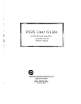
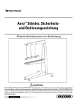
REAL TIME
CLOCK/CALENDAR
MODULE
FOR
COPYRIGHT' 1982
DUAL SYSTEl'v\S CORPORATION
FORM 880008 REVISED 09-20-82
ALL RIGHTS RESERVED
,
E
IEEE~696/S~100
odel
l
COMPUTER SYSTEMS
L
DUAL SYSTEMS CORPORAllON
2530 San Pablo Avenue" Berkeley" CA 94702 " (415) 549-3854 " 172029 SPX
po-
,...--
REAL TIME
CLOCK/CALENDAR
MODULE
~
L
I-
Model
CLK-24C
I....--
COPYRIGHT' 1982
DU AL SYSTEMS CORPORATION
FORM 880008 REVISED 09-20-82
ALL RIGHTS RESERVED
fOR IEEE-696/S-100 COMPUTER SYSTEMS
USER'S MANUAL
DUAL SYSTEMS CORPORATION
:)UAL
-s-ys-te-m-re-lia-bi-lity-/-sy-st-em-i-nt-eg-rit-y---
2530 San Pablo Avenue • Berkeley • CA 94702 .. (415) 549-3854 .. 172029 SPX
WARNING
Your Dual Systems CLK-24 non-volatile clock/calendar board is
equipped with a new LITHIUM battery.
This long-life battery will
keep time/date intact for three years (minimum) from date of
purchase.
Ho~ever,
board is placed on
~
this battery
~ill
be RUINED if the CLK-24
metal surface or accidentally allowed to be
shorted out Qy coming into contact with metal objects.
a charge of $10.00 plus shipping for
batteries.
There is
replacing of these
THEREFORE, DO NOT ALLOW THE CLK-24 TO COME INTO
CONTACT WITH METAL OBJECTS.
WHEN THE BOARD IS NOT ACTUALLY
INSTALLED IN A COMPUTER SYSTEM,
PROTECTIVE PINK ANTI-STATIC. BAG.
IT SHOULD BE STORED IN ITS
Real Time Clock/Calendar Module
CLK-24
User's Manual
o.
Introduction •••••••.•.•..••••....•..........•••• 2
Specifications ••.....•••....•..••••..•••..• 3
1.
Board Setup and Initial Configuration .•...•..••• 4
Unpacking .•••.•..•.•••...••.••...•••..•.••• 4
Port Address Selection ..•..•••.••••...•.••. 4
Write Protect Switch ..••.••••..•.....••••.. 5
Installing the CLK-24 ••••••••••••••..•••••• 5
0-1.
1-1.
1-2.
1-3.
1-4.
2.
2-1-
2-1-1.
2-1-2.
2-2.
2-3.
3.
3-13-1-1 .
3-2.
3-2-1.
How to use the CLK-24 ....••..•...•••..•••••••••• 6
Control Codes and Special Functions ..•••••• 7
Control Codes •...•••..••.•..•.•.•.•••• 8
Special Functions ••.••.•.•••••..•.•..• 8
CLEAR Control Code •....•..•.••..•..•..•.••• 9
Time Setting Protection ••...•..•..•••.•.•• 11
Programming in BASIC ••••••••••..••....••••.•.•• 12
Reading the Time in BASIC .•..•..•.•.•.•••• 12
Sample Read Program •........••.•.•.•. 14
Setting the Time in BASIC •..••••...••.••.. 15
Sample Write Program ••.•..••...•.••.• 15
4.
4-1.
Programming in Assembly Language •••..•••••••••. 16
Sample Program in 8080/8085/Z-80
Assembly Language
16
5.
5-1-
Using Interrupts ••....•...••••.•.••.•.••....... 18
Sample Interrupt Program in
68000 Assembly Language •.....•.••.••..•. 21
Sample Interrupt Program in
z-80 Assembly Language •.••••.•....•.•.•• 22
5-2.
6.
6-16-2.
6-2-1 .
6-2-2.
6-3.
Theory of Operation .•.••...•.•••.•••••....•••.. 23
Control Register ••......•..•.••...•.••.... 23
Tim i ng . ~
Read Cycle
III
,.
..
II!
I!l
II
!I!
..
II
'1l
~
'"
I!I
l!I
a
II!
III
II>
III
11"
III
""
'"
....
III
""
!'6
•
III
III
•
"
...
t.l
It
"
•
l!I
,.
..
III
iii
'"
10
•
""
011
..
25
25
Wri te Cycle •••••.......•...••••.•••.• 26
Explicit Description of Control Codes ...•. 27
Appendices
A.
B.
C.
D.
E.
F.
G.
Using the Hold Disable Pin •...•....•...•.•..... 28
Battery Replacement .....•.•••...•.•.••••••.•... 29
Note to Users of
CLK-24 purchased before 5/12/81 •...•.•.•..••• 30
In Case of Trouble •••••••..•.....•••.....•....• 31
OK1 Clock Chip Data Sheet
32
Schematic Drawing .......••.•.•....••••......... 36
Programmi ng Summary .....••......•..•........•.. 37
-1-
o.
INTRODUCTION
The Dual Systems model CLK-24 is an industrial grade realtime clock/calendar board that provides the date and time to any
computer that meets the IEEE S-100 bus standard.
The heart of the CLK-24 is a new CMOS large-scale integrated
circuit, the OKI MSM5832, which can be read by the computer to
give the current time or date. The CMOS integrated circuit uses
so little power that with one small battery it can keep time for
over three years with the computer power off.
The CLK-24 is easy to use. The time and date may be set or
read from either BASIC, assembly language, or any other language
that allows access to the I/O ports. Programming examples are
included in this manual which can be used as a framework for
building systems using the CLK-24.
For critical timing applications or operating system
requirements the CLK-24 can generate vectored interrupts on
intervals of minutes, seconds, 1/64 second and 1/1024 second.
This is useful if, for example, you wish to display the current
time every second or minute, concurrent with normal system
operation.
WARNING:
Do not place the CLK-24 directly on a metal sur:face.
To do this will resul t in a short circui t which will damage the
battery, and void the warranty.
-2-
0-1.
FUNCTION:
SPECIFICATIONS
Precision real time clock and calendar wi th on- board
ba t tery backup.
BUS INTERFACE:
Plugs into virtually any S-100 type computer. Meets
the IEEE 696/S-100 standard.
Compatible with GODBOUT
COMPUPRO,
NORTH STAR HORIZON,
IMSAI,
ITHACA
INTERSYSTEMS, IMS, and CROMEMCO , as well as the new
16 bit systems (e.g. Dual Systems CPU/68000.)
IEEE 696 BUS COMPATIBILITY:
Slave (D8) (18)
VI
F5
T60
W
(SH)
TIME KEEPING FUNCTIONS:
Provides current year, month, day, day of week,
AM/PM, hour (12 or 24 hour format), minute, and
second. Also provides jumper selectable interrupts
every minute, second, 1/64th second or 1/1024th
second. Each of these intervals can be jurnpered to
any of the eight interrupt levels, or NMI.
ACCURACY:
± 50 seconds per month.
Controlled by 32.768 KHz
tuning fork resonator with accuracy, in normal use, of
better than ± 20 parts per million. On board trimmer
is provided to adjust the clock accuracy.
OPERATING POWER:
Operates from the +8 volt (nominal) line on the S-100
bus.
Usable operating range is +7.5 to +14 volts.
Current consumption is less than 250 rnA during
operation (typically 175mA).
STANDBY POWER:
Supplied by a 3-10 year sealed 3.6 volt lithium
battery on the CLK-24 board. Current consumption is
30 uA maximum, 13 pA typical.
TIMEKEEPING DURATION WITH COMPUTER POWER OFF:
With factory supplied battery:
three
between battery replacements.
-3-
years
minimum
1.
1-1.
BOARD SETUP
UNPACKING:
Carefully remove the board from its protective antistatic
bag. Do not place the CLK-24 on any metal surface, as this may
accidentally discharge the battery.
1-2.
PORT ADDRESS SELECTION:
The CLK-24 has two registers, the data register and the
Control Register.
Each is accessed through an 110 port.
Notice
that there is only one 110 address switch on the board.
switch sets the data port address.
This
The Control port address is
always the data port address + 1. The swi tch sets the data port
to any even address (eg. 0, 2, 4, .. 252, 254). For example, if
the data address is 240 (as delivered) the Control address is
241.
Before installing the CLK-24 it is important to make sure
that the two addresses selected are not used by any other part of
the computer system.
Check the serial 110, disk 1/0, bank
select, extended addressing port, and any other 1/0 mapped
devices in your system to be sure the addresses do not conflict.
The CLK-24 is factory configured with a data port address of
240
decimal
(FO
Hex)
which
standard computer systems.
should
be
compatible with most
To change this address
it is
necessary only to change the DIP switch settings on the board.
Each switch selects one address bit (A7 to A1). When a switch is
"ON" (UP position), that address bit is a logical O.
When a
switch is "OFF" (DOWN), that bit is a logical 1.
the arrangement and values of these switches.
-4-
Figure 1 shows
Value
Name
Switch No.
UP: 0
DOWN: 1
4 8 16 32 64 128
.
A2~
A3 A4 A
A5 A6 A7
1
WRITE ENABLE
2
..
••
~
FIGURE
WRITE PROTECT
,.
Adding up the values of all the switches set for logical 1
gives the value of the base address.
Example:
The board is
delivered with the switches set as shown in Figure 1. The base
address is then 128 + 64 + 32 + 16:
1-3.
240 decimal.
WRITE PROTECT SWITCH:
The position 8 paddle on the DIP sWit<;?h shown in Figure 1
is the Write Protect Switch.
When the switch is in the UP (on)
position, the CLK-24 will allow the time & date to be reset or
changed.
When the switch is in the DOWN (off) position the
previously set time is protected from being changed. To be safe,
always keep the Write Protect Switch in the protect mode (DOWN),
except when changing the time.
1-4.
INSTALLING THE CLK-24:
Once the data address has been set, the CLK-24 may be
installed into the computer system. The power HUST BE TURNED
OFF, and left OFF for at least 30 seconds. and then the board may
be placed into any unused slot in the S-100 card cage.
Be sure
the gold tabs on the board are lined up with the socket on the
motherboard and then carefully press the board all the way into
place.
Be sure the battery
adjacent board.
on.
does not accidentally touch the
If everything appears correct, turn the computer
-5-
2.
HOW TO USE THE CLK-24
The time is read from or written to the CLK-24 one digit at
a time. The Control port is used to set the mode of the CLK-24
and select which digit is to be read or written. The digits are
read or written through the data port.
To READ a given digit, simply OUTPUT the Control Code for
that digit to the Control Register and INPUT the digit from the
data port.
To WRITE a given digit, simply OUTPUT the digit to the data
port, then OUTPUT the Write Control Code (Control Code + 16) for
that digit to the Control Register, lastly OUTPUT the CLEAR Code
to the Control Register.
The following algorithm READS the time from the CLK-24:
1) OUTPUT Control Code for the desired digit (e.g. seconds
units, seconds tens, etc.) to the Control port.
2) INPUT the digit from the data port.
3) REPEAT Steps 1 and 2 until all digits are read then
OUTPUT the CLEAR Code.
The following algorithm WRITES the time to the CLK-24:
1) OUTPUT the desired digit to the data port.
2) OUTPUT the Control Code plus the Wri te Code to the
Control port. (The Write Code is 16.)
3) OUTPUT the CLEAR Code to the Control port after EACH
digi t is wri t ten.
4) REPEAT Steps 1 through 3 until all digits are written.
The INPUT and OUTPUT functions for the CLK-24 can be
executed using the appropriate input-output instructions for 1/0
ports. These are the INP and OUT instructions in BASIC, the IN
and OUT instructions in 8080 assembly language, or the
appropriate MOVE instructions in 68000 assembly language.
-6-
There is a restriction on the minimum amount of time which
must elapse between setting the Control Port and reading the Data
Port.
This restriction is usually satisfied in high level
languages, under a normal instruction set; but, in assembly
language it might be necessary to program this delay. Please
refer to Section 6 for further details.
The clock chip requires 150 pSec to either read or set the
time. The CLK-24 incorporates circuitry to automatically suspend
the operation of the computer for this period. The user is then
unburdened of this task. See Section 6 for further details.
2-1.
CONTROL CODES AND SPECIAL FUNCTIONS:
The Control Register Codes given below are used to select
which digit of the date or time is to be read or written.
Control Codes are also used to select the read or write mode.
Table 1 summarizes these Contol Codes and Special Functions.
Refer to Section 6-3 for an explicit description.
DIGIT
WHEN READING
WHEN WRITING
#
o
1
2
3
4
5
6
7
8
9
10
11
12
16
64
128
143
1·
10
1
10
1
10
SECOND
SECONDS
MINUTE
MINUTES
HOUR
HOURS
"AND" DIGIT WITH 3
DAY OF WEEK*
1 DAY
10 DAYS
"AND" DIGIT WITH 3
1 MONTH
10 MONTHS
1 YEAR
10 YEARS
ADD 4 FOR PM, 8 FOR 24
HOUR FORMAT.
ADD 4 FOR LEAP YEAR
WRITE
CLEAR
HOLD DISABLE (OPTIONAL)
ENABLE INTERRUPTS
* 0 is SUNDAY .•. 6 is SATURDAY
TABLE
1.
Control Register Codes, & Special Functions.
..7-
2-1-1.
CONTROL CODES:
Recall that the Control Code must be sent to the Control
Register for every digit, either before the digit can be read
from the data port, or after the digit has been written to data
port.
The Control Code for the read functions is simply the
Control Code for that particular digit.
(e.g. reading the
minutes digit of the time simply requires the Control Code to be
2.) To derive the Control Code for writing a digit, simply add
the Control Code for the Write function to the Control Code for
that particular digit. (e.g. setting the minutes digit of the
time requires the Control Code to be 2+16 = 18.)
The Days of the week are encoded as follows:
1 is Monday, ••. , 6 is Saturday.
2-1-2.
0 is Sunday,
SPECIAL FUNCTIONS:
The CLK-24 provides the following Special Func~ions:
Selection of either the AM/PM format or the 24 Hour format; and,
recognition of a leap year. These functions are encoded in the
data for two digits. These are the tens of Hours and tens of
Days digit. Table 1 summarizes these functions.
The '10 Hours' and the '10 Days' digits serve multiple
purposes. The additional information contained in the '10 Hours'
digit is for selecting the 12 hour AM/PM format or the 24 hour
format. The additional information contained in the '10 Days'
digit is for selecting a leap year.
When INPUTTING the data for both of these digits 'AND' the
data with 3, to mask out the extra information, making the value
for that digit useable.
To determine whether the time is in the AM or the PM, the
12/24 hour data must be masked out. This is done by 'AND'ing the
input data for the '10 Hours' digit with 7 when the data is first
input, before doing anything else. Now if the remaianing value
-8-
is greater than 3, the time is in the PM, otherwise it is in the
AM. Next, to get the value of the '10 Hours' digit simply mask
out all extra information by 'AND'ing the remaining data with 3,
as above.
To determine whether the year is a leap year, simply compare
the unmasked '10 Days' digit to 3. If it is greater than 3, then
the year is a leap year, otherwise it isn't a leap year. Next,
just 'AND' the data with 3, to mask out the leap year
information.
When setting the time, to select the AM/PM format, 'ADD'
four (4) to the '10 Hours' digit before OUTPUTTING it to the CLK24.
To select the 24 hour format, 'ADD' eight (8) to the '10
Hours' digit before OUTPUTTING it to the CLK-24. To select a
leap year, add four (4) to the '10 Days' digit before OUTPUTTING
it to the CLK-24. Following are some examples of how to use the
special functions provided with these digits:
- to set the time such that the 10's of hours digit is 1,
say 1:22 PM, the digit must be set with 1+4 = 5; but to set
the time to 1:22 AM, the digit must simply be set with 4.
The Control Code in both cases would be 5+16 = 21.
- to set the date to, say 1-21-82 (not a leap year), the
10's of days digit must simply be set with 2+0 = 2; but to
set the date 1-21-84 (a leap year), this digit must be set
wi th 2+4 = 6. The Control Code in both cases would be 8+ 16
= 24"
2-2.
CLEAR CONTROL CODE
Most clocks that read one digit at a time have a potential
source of error.
Suppose it is 1:59. Your program reads the
clock starting with 10's of hours ending with 1's of minutes.
Suppose the time changes from 1:59 to 2:00 after the l's of hours
digit has been read. The time is now 2:00 and the program will
procede to read the 10's and 1's of minutes.
Both of those
digits will now be O. Thus the program will read the incorrect
time of 1:00.
The CLK-24 has been designed to eliminate this problem.
-9-
Circuitry on board latches the time so that whenever you read the
clock, the time is stable for 1/2 second. This does not affect
the accuracy of the clock in any way.
All readings within the
1/2 second will be consistent. After the 1/2 second the clock is
again allowed to advance. If you wish to read the time more than
once per second, then you must signal to the CLK-24 to update the
time out of sequence.
(You want the clock to advance BETWEEN
complete date/time readings.)
This is done with the CLEAR
Control Code. If the CLEAR Control Code is not used, subsequent
time readings within the 1/2 second interval will yeild the same
resul t.
The following algori thm will accurately read the time,
even at a rate of more than once per second:
1)
2)
3)
READ the entire time once.
OUTPUT CLEAR Control Code;
Jump to 1; (perform next entire read)
Similarly, most clocks that set time one digit at a time
also have a potential source of error. Since many digits may
need to the set, either one of the following extremes could cause
the time to be incorrectly set:
1)
If the time setting routine is too slow, then it is
conceivable that the desired time will have advanced
before the routine is finished setting the previously
desired time.
2)
If the time setting routine is too fast, then it is
likely that the routine will not allow enough time for
the actual write function to be completed.
The CLK-24 has been designed to eliminate these problems
also.
The CLEAR Control Code is very useful here because it
produces an appropriate delay for the completion of a write
function to the clock.
The following algori thm will provide an
optimum time setting procedure:
1)
2)
3)
4)
Prepare and OUTPUT next digit to Data Port;
OUTPUT the appropriate value to the Control Port;
OUTPUT the CLEAR Control Code;
Jump to 1; (prepare and 'write' next digit)
-10-
2-3Q
TIME SETTING PROTECTION
The CLK-24 has four features to prevent accidental wri ting
of the time.
ENABLE.
The rightmost DIP switch (#8) is labelled WRITE
When this switch is ON (up) the clock can be set.
it is OFF, the board is write protected.
When
We suggest that you
leave the board in the WRITE PROTECTED (switch OFF) position all
the time except on the rare occasions that the time must be
set~
Write errors are usually caused by microprocessors which
execute random programs as the power falls (either when the
computer is turned off or during a power fail).
The CLK-24 is
designed so that data can be written to the clock only AFTER the
proper sequence of instructions are executed. This means that a
single random OUT instruction cannot affect the clock, even if
the clock
is left with the WRITE PROTECT switch not
protect mode.
in the
(See Section 1.3)
In addition, the CLK-24 monitors the S-100 power supply and
detects when the power starts to drop.
It also monitors the
PWRFAIL* (powerfail) line on the bus which will go active when
the power is about to fail (if your computer has this new IEEE-
696/S-100 feature).
When any of these conditions occur, the
CLK-24 board is deselected.
-11-
3.
PROGRAMMING IN BASIC
3-1.
READING THE TIME IN BASIC
The following BASIC fragment will read the day of week (0
for Sunday to 6 for Saturday), and store this number in the
variable "DAY".
100
110
OUT 241,6
DAY = INP(240)
:REM 6 IS CONTROL CODE FOR DAY OF WEEK
:REM READ DATA
This and all programming examples assume that the CLK-24 is
configured with a base address of 240 (see section 1-2).
In
addition, all examples in BASIC are written in Microsoft BASIC-80
for CP/M.
Note that 10's of hours and 10's of days serve additional
functions (i.e. AM/PM,leap year, etc.). The extra bits must be
masked (removed) when the digit is read.
For example, this
program fragment reads the hours:
100
110
120
130
140
: REM SET CONTROL REG. FOR 1'S OF HOURS
OUT 241,4
: REM READ 1'S OF HOURS
UHOUR = INP(240)
: REM SET CONTROL REGISTER FOR 10'S HRS
OUT 241,5
THOUR = INP(240) AND 3 :REM STRIP AM/PM BIT
PRINT "HOURS= "; THOUR; UHOUR
The BASIC "AND" statement here removes all but the two
least significant bits of the digit from the data port.
Some versions of BASIC.do not provide the AND statement so
you must use the INT function or the IF statement to do the same
work. To remove the format and PM bits from the 10's of hours
you can execute:
100 THOUR=THOUR - (4*INT(THOUR/4» :REM MASK ALL BUT 2 LOW BITS
(The above is identical to THOUR=THOUR AND 3.)
-12-
If you know that only single extra bit may be set, then
check for that bit explicitly. For example, if you read the
of days and want to remove the leap year bi t then you
execute:
:REM REMOVE LEAP YEAR
100 IF TDAY > 3 THEN TDAY = TDAY - 4
you can
10's
can
BIT
In most applications, however, you will be reading more than
one digit at a time. A loop is a more efficient way to do this.
For example, the following program reads the time and prints it
out as fast,as possible:
'I
1000
1010
1020
1030
1040
1050
1060
1070
1080
1090
CR=241 : DR=240
:REM DEFINE PORT ADDRESSES
DIM T(6)
:REM ARRAY TO HOLD THE DATA
FOR 1=0 TO 5
:REM LOOP FOR ALL DIGITS
OUT CR,I
:REM SEND CONTROL CODE FOR DIGIT
T(I)=INP(DR)
:REM READ DIGIT FROM THE DATA PORT
NEXT I
OUT CR,64
:REM SEND "CLEAR" CONTROL CODE
T(5) = T(5) AND 3
:REM STRIP AM/PM BIT FROM HOURS
PRINT T(5);T(4);":";T(3);T(2);":";T(1);T(0) :REM PRINT TIME
GOTO 1020
:REM DO AGAIN
Note that we have used the algorithm as described in section
2-2. Since this program will be reading the time faster than
once per second, we output a CLEAR Control Code to the Control
Register so that the next reading of the CLK-24 will yield a more
recent time. The command used to send the CLEAR Control Code is:
1060
OUT CR,64
Again, this is only needed in programs which read the time
more than once per second, such as programs which repeatedly read
the time while waiting for a certain reading.
-13-
3-1-10
SAMPLE READ PROGRAM:
The following is a more complete program which determines
the time, date, and day of week. It also uses the status bit to
determine AM/PM.
In most programs which do any extensi ve
processing of the data it is useful to store the data in a string
or array before further processing. Storing the data simplifies
the program structure and also has another advantage: If the
clock is read continuously for more than 1/2 second then there is
some chance that the time will change during the reading (see
section 2-2.). If you store the data directly into an array then
you can be sure that all digits will be read in less than 1/2
second regardless of what other processing or printing is done.
:REM AN ARRAY FOR TIME AND DATE
1000 DIM D(12)
:REM SET NAMES OF CONTROL AND DATA PORT
1010 CONTROL=241:DTA=240
:REM LOOP FOR ALL 12 DIGITS OF INFO
1020 FOR 1=0 TO 12
:REM SET UP TO READ I,TH DIGIT OF DATA
1030 OUT CONTROL,I
1040 D(I)=INP(DTA)
:REM READ DIGIT AND SAVE IN ARRAY
10S0 NEXT I
10SS OUT CONTROL,64
:REM SEND "CLEAR" CONTROL CODE
1060 D(S)=D(S) AND 7
:REM STRIP 12/24 HR BIT (BIT 3)
1070 IF D(S) > 3 THEN M$="PM" ELSE M$="AM" :REM CHECK BIT 2 FOR AM/PM
1080 D(S)=D(S) AND 3
:REM STRIP AM/PM BIT (BIT 2)
lOgO D(8)=D(8) AND 3
:REM STRIP LEAP YEAR BIT
1100 P$=""
:REM SET PRINT STRING TO NULL
1110 FOR 1=0 TO 12
:REM LOOP THROUGH ALL DIGITS
1120 P$ = HEX$(D(I» + P$
:REM CONVERT TO ASCII AND ADD TO STRING
1130 REM NOTE THAT EACH NEW CHAR IS ADDED AT LEFT END OF STRING
1140 NEXT I
:REM COUNT UP TO DAY OF WEEK
11S0 FOR 1= 0 TO D(6)
1160 READ DAY$
:REM READ NAME OF EACH DAY
1170 NEXT I
:REM EXIT WHEN WE REACH THE RIGHT DAY
1180 REM NOW PRINT DAY
MONTH/DAY/YEAR
11g0 PRINT DAY$, MID$(P$,3,2) + "/" + MID$(P$,S,2) + "/" + LEFT$(P$,2),
1200 REM NOW PRINT
HOUR:MIN:SEC
AM/PM
1210 PRINT MID$(P$,8,2) + ":" + MID$(P$,10,2) + ":" + RIGHT$(P$,2), M$
1220 RESTORE
:REM RESET READ DATA
1230 GOTO 1020
:REM READ DATA AND TIME AGAIN
1240 DATA "SUN","MON","TUES","WED","THURS","FRI","SAT"
-14-
3-2.
SETTING THE TIME FROM BASIC
To set the day of week to Monday, use the following BASIC
fragment:
100 OUT 240, 1
110 OUT 241, 16 + 6
120 OUT 241, 64
:REM SEND "MONDAY" TO DATA PORT
:REM SEND TO CONTROL "WRITE" (16) +
CODE FOR DAY OF WEEK (6)
:REM SEND CLEAR CODE TO CONTROL PORT
Note the use of the CLEAR Control Code.
3-2-1.
SAMPLE WRITE PROGRAM
The following program sets the time and date.
Data
statements and read statements are used for the prompts. Data is
read from the terminal one digit at a time and stored in an
array. Then a loop is used to send all the data to the clock.
10
20
30
40
SO
60
70
80
90
100
120
130
140
1S0
160
170
180
CONTROL=241:DTA=240
:REM PORT ADDRESSES
DIM SET(12)
:REM ARRAY TO HOLD DATA
FOR"I= 2 TO 12
:REM LOOP FOR ALL DIGITS BUT SECS
READ MES$
:REM READ A PROMPT
PRINT MES$;
:REM PRINT IT
INPUT SET(I)
:REM INPUT ONE DIGIT
NEXT I
INPUT "AM? (Y OR N)",A$
:REM ASK IF AM OR PM
IF A$="N" THEN SET(S)=SET(S)+4 :REM SET PM BIT TO HOURS DATA
FOR I= 0 TO 12
:REM LOOP TO WRITE ALL DIGITS
OUT DTA,SET(I)
:REM SEND DIGIT TO DATA PORT
OUT CONTROL,16+I
:REM SEND WRITE CODE + CONTROL CODE
OUT CONTROL,64
:REM SEND "CLEAR" CODE
NEXT I
DATA "MIN 1","MIN 10","HR 1","HR 10" :REM DATA FOR TIME PROMPTS
DATA "DAY OF WK? (SUN=O .. SAT=6)"
:REM DAY OF WEEK PROMPT
DATA "DAY 1","DAY 10","MO 1","MO 10","YR 1","YR 10" :REM DATE PROMPTS
-15-
4.
PROGRAMMING IN ASSEMBLY LANGUAGE
SAMPLE PROGRAM IN BOBOIBoB5/Z-BO ASSEMBLY LANGUAGE:
4.1
The following program reads a pair of digi ts from the CLK24, converts the two digits from hex to BCD digits, then stores
each pair of digits in a memory location as shown in the table
below.
DATA
DEST.
DAY
YEAR
HOURS
MINUTES
SECONDS
11H
12H
13H
14H
15H
CLOCK FUNCTION CODES
7,B
TABLE
11,12
4,5
2,3
0, 1
2.
These locations are unused by the CPIM operating system and
are accessed by Sorcim's Pascal/M for the time functions.
Hopefully they conform to some kind of standard.
The only critical timing consideration when programming the
CLK-24 in assembly language is to be sure that you allow at least
6 microseconds between outputting to the Control port and
inputting a digit from the data port.
DATAR:
CONTR:
SECS:
REST:
ORG
EQU
EQU
0100H
0240D
0241D
MVI
LXI
CALL
CALL
CALL
ANI
MOV
MVI
CALL
MVI
CALL
ANI
MOV
CALL
RET
B,OOH
H,0016H
PAIR
PAIR
PAIR
03FH
M,A
B,11D
PAIR
B,7D
PAIR
03FH
M,A
PAIR
ADDRESS OF DATA REGISTER
ADDRESS OF CONTROL REGISTER
CLOCK FUNCTION FOR SECONDS
MEMORY LOCATION FOR SECONDS + 1
GET SECONDS
READ MINUTES
; READ HOURS
MASK PM AND 24 HR BITS
SAVE CORRECT DIGITS
FUNCTION CODE FOR YEARS
READ YEARS
FUNCTION CODE FOR DAYS
READ DAYS
MASK LEAP YEAR BIT
SAVE CORRECT DIGITS
READ MONTHS
DONE
-16-
****************.*********.*.*.************.*****************************
**
'PAIR' READS A PAIR OF DIGITS FROM THE CLOCK BOARD AND RETURNS
**
•
WITH THE TWO DIGITS (IN BCD) IN THE ACUMULATOR. THE ROUTINE ALSO
*
* DECREMENTS THE HL PAIR AND THEN STORES THE PAIR OF DIGITS IN *
* MEMORY POINTED TO BY HL. UPON ENTRY, THE B REG SHOULD HAVE THE *
* CLOCK CONTROL CODE FOR THE FIRST DIGIT. THE HL PAIR SHOULD HAVE *
* ONE MORE THAN THE DESTINATION IN MEMORY OF THE PAIR OF DIGITS. *
* THE HL PAIR WILL BE DECREMENTED SO THAT UPON EXIT, IT WILL POINT *
* TO WHERETHE DATA WENT. ALSO, THE B REGISTER IS INCREMENTED *
* TWICE TO ANTICIPATE THE CLEAR CLOCK CONTROL CODE.
*
*****.****.******* •• *•• *••• *.*** •••••••• ****.* •• *.*.* •• *•••• ***.***********
PAIR:
MOV
OUT
NOP
NOP
NOP
NOP
INR
IN
MOV
MOV
OUT
NOP
INR
DCX
IN
RLC
RLC
RLC
RLC
ORA
MOV
RET
A,B
CONTR
GET CLOCK CODE IN A
; SET UP CLK-24 FOR READING DIGIT
WAIT FOR DATA VALID (6 USEe)
NEXT STATEMENT ALSO KILLS TIME
PREPARE FOR NEXT READ
READ DIGIT
SAVE DIGIT FOR LATER
GET CLOCK CODE INTO A
SEND CONTROL CODE
ANOTHER DELAY
ANTICIPATE NEXT READ
PREPARE FOR NEXT DESTINATION
READ HIGH DIGIT
ROTATE HIGH DIGIT INTO HIGH 4 BITS
B
DATAR
C,A
A,B
CONTR
B
H
DATAR
MERGE HIGH AND LOW DIGITS
STORE INTO MEMORY
C
M,A
-17-
5.
USING INTERRUPTS
Interrupts are used when sub-second precIsIon is needed from
the clock, or for real-time applications where polling (checking
the clock continously until the right time is reached) is not
appropriate. The CLK-24 can provide interrupts at 4 different
rates: once every minute, every second, every 1/64th second or
every 1/1024th second (.97 millisecond). The correct interval
should be jumpered to the desired interrupt level. Pins are
provided for connection to the S-100 interrupts VIO-VI7, as well
as NMI. These pins may be found at the bottom left of the board,
below U9 and U10. The "MIN" jumper has a dual function. It will
provide either a 1 minute interrupt, or a 1/64 second interrupt,
depending on the position of jumper J5, shown in figure 2b.
Method of connection is demonstrated by the example in figure 2a.
til
S
Example showing connection
of 1-second interrupt interval
to S-100 vectored interrupt
level 5 (VI5)
Iii
.
....
....
~
til
I
I
~
I
I
I
I
Z
~
o
H
:>
r-f
N
M
~ ~ 30 gauge wirewrap wire
"""
\0
r-11)
H
:>
FIGURE
2.a.
.. .
••
A
••
t
•
• • •
•• :
••
•••
•
•
~ .~
U7
•
YlIII
Jumper for 1/64
second into
FIGURE 2 .. b ..
..
J~per
for
minute interrupt.
The use of interrupts is tied to the characteristics of the
host CPU, and it is necessary to have some understanding of the
behavior of the CPU on receipt of an interrupt request. When the
interrupt is received, the processor finishes the current
instruction, saves the current address (PC), and jumps to a
specific memory location. Some sort of interrupt service routine
must previously have been stored at that location.
-18-
The exact behavior, and especially the memory location to
which execution jumps,
depends on the CPU. Two examples are
provided in the table below:
Host Processor
3-100 int
VI7
VI6
VI5
VI4
VI3
VI2
VI1
VIa
NMI
68000
z-80
jump to 38 (hex)
" " 30
" " 28
" " 20
" " 18
" " 10
"
"
not supported
not supported
( IP1) jump to
(IP2)
" "
(IP3)
"II "
(IP4)
"
(IP5)
"
" It
(IP6 )
"
(IP7)
" It
8
jump to 66 (hex)
TABLE
64 (hex)
68
6C
70
74
78
7C
3.
Note that the space provided for each interrupt level is
insufficient to hold an entire interrupt service routine. They
should only contain a jump to the proper routine. For the Z-80,
the actual machine code for the JMP instruction must be provided,
along with the address. For the 68000 only the address (4 bytes)
is to be supplied. The NMI is different from the other interrupts
in that it is non-maskable (i.e.,
may not be inhibited). The CP/M
operating system uses location 66, making NMI unavailable for
those systems which use CP/M.
It is the responsibility of the interrupt service routine to
make sure that
any registers
program are preserved,
so
being
that
used
by
the
interrupted
once the service routine
is
exited, execution can be resumed by the main program as if there
had been no interrupt (the main program should not be aware of
the occurrence of interrupts). The most common technique is to
push everything that must be preserved onto the stack. It is very
important, however, to make sure that everything pushed onto the
stack is popped before the service routine is exited, since the
information needed by the processor to return is generally on the
stack as well.
-19-
To enable the CLK-24 interrupts, once the proper jumpers
have been installed on the board, output the code 143 (8F hex) to
the Control port. The service routine should acknowledge the
interrupt (clear the interrupt line) by outputting the code 142
(8E hex) to the Control port. (See section 2-1 for details on the
Control Codes).
The following sample program will demonstrate simple use of
the CLK-24 interrupts. All that is done in this example is to
increment a counter each time an interrupt is received. A
possible use of this routine would be to time the execution of a
program. The program would start up the clock, execute, and then,
on termination, read the counter to see how many interrupts had
occurred. The time would be the number of interrupts times the
interrupt interval.
The following program is presented in two versions, one in 68000
assembly language, and the other in 8080 assembly (for use on the
8080 or Z-80). In each case, the clock's interrupt level has
been jumpered to the 3-100 VI5 pin, as in the example in the
beginning of this section (see Figure 2).
-20-
5-1.
*
**
SAMPLE INTERRUPT PROGRAM IN 68000 ASSEMBLY LANGUAGE:
*
CLK-24 interrupt service example (68000 processor)
*
***INIT*** should be called when the interrupts are to be
started up, probably at the beginning of the program
*
*lOPAGE
CTL
DATA
ENlNT
DISABLE
VECTOR
**
*INIT
COUNT
EQU
EQU
EQU
EQU
EQU
EQU
$FFFFOOOO
241 + lOPAGE
240 + lOP AGE
$8F
$8E
$64
*
*
*
*
*
*
*
1/0 locations for DUAL CPU/68ooo
Clock control port
Clock data port
Enable interrupt code
Interrupt acknowledge code
Interrupt jump location: 64 hex for
68000 IP1 (S-100 interrupt VI5)
***INIT*** initializes the clock and the counter
MOVE.W
MOVE.L
MOVE.B
JMP
#0, COUNT
initialize counter to 0
#INTACK, VECTOR store addr of service routine
RENINT, CTL
enable interrupts
MAIN
jump to main program
DS.W
o
*
***INTACK***
*INTACK
MOVE.B
*
ADDQ.W
MOVE.B
MOVE.W
RTS
define storage area for count
services the interrupt from the CLK-24
RDISABLE, CTL
t/1, COUNT
fIENINT, CTL
flO, SR
-21-
disable interrupts
increment counter
enable clock interrupts
reset CPU interrupt mask
and return to caller
5-2.
••
••
•
•
•
DATA
SAMPLE INTERRUPT PROGRAM IN Z-80 ASSEMBLY LANGUAGE:
CLK-24 interrupt service example (Z-80 processor)
•• *INIT* •• should be called when the interrupts are to be
started up, probably at the beginning of the program
CTL
ENINT
DISABLE
VECTOR
JUMP
EQU
EQU
EQU
EQU
EQU
EQU
241
240
08FH
08EH
028H
OC3H
•
clock data register
; clock control register
enable interrupt code
; interrupt acknowledge code
; jump location for level 5 interrupt
; machine code for JMP instruction
*·*INIT·*· initializes
*
*INIT:
XRA A
COUNT
the clock and the counter
STA
MVI
STA
LXI
SHLD
MVI
OUT
EI
RET
COUNT
A,JUMP
VECTOR
INTACK
VECTOR+1
A,ENINT
CTL
initialize counter to zero
load code for jump
store
load addr of service routine
and store
DW
0
define storage area for count
•• *·*INTACK*·* service
•INTACK: PUSH PSW
MVI
OUT
LDA
INR
STA
MVI
OUT
POP
RET
enable clock interrupts
enable interrupts
the interrupt from the CLK-24
save status
A,DISABLE
CTL
COUNT
acknowledge clock interrupt
get counter
increment
and store
A
COUNT
A,ENABLE
CTL
PSW
reenable clock interrupts
get status back
-22-
6.
THEORY OF OPERATION
This section discusses, in more technical detail, the
operation of the CLK-24.
The information contained wi thin will
be useful for determining the Programming approach for
applications where timing restrictions are strict.
6-1.
CONTROL REGISTER:
The Control Register sets the mode of the CLK-24.
the following bit definitions:
D7
D6
D5
D4
D3
D2
D1
DO
CONTROL REGISTER
(switch address+1)
-
It has
hold disable
clear
x
write
B3
B2
B1
BO
-
-
-
"X" means "unused"
FIGURE
3.
READ/WRITE Bit:
When this bi t is HIGH then the board WRITES the digi t in the
data latch to the clock. When this bit is LOW then the board is
set for READING.
HOLD DISABLE Bit:
The hold disable bit allows more direct control over the
clock board for faster reading. It disables the HOLD pin on the
clock chip and disables the automatic wait state generation
needed for the relati vely SLOW clock chip.
-23-
The use of this feature is only suggested for assembly
programs which are interrupt driven or for systems which cannot
tolerate the 150 pSec wait states.
Host assembly language
programs should access the CLK-24 just as the BASIC programs
outlined above.
The clock chip has a HOLD pin which keeps the data from
changing between successive reads. Whenever the HOLD pin is set
the clock chip requires a 150 ~Sec setup time before any other
acti on can take place. Normally the CLK-24 board takes care of
all timing on this pin (With the help of the CLEAR instruction.)
The HOLD DISABLE bit is included to allow user programs to
override the automatic HOLD generation and wait states. This
should only be needed for interrupt driven programs where high
speed is important.
When the Control Code is sent to the clock, there must be 6
uSec for the data to stabilize before attempting to read it.
(see clock chip data sheet included). This is only a factor in
assembly language.
Remember, there is some chance that the time will change
between digit readings. Therefore, if you must use the HOLD
DISABLE bi t, the recommended procedure is to store all the read
data in an array. Then read the digits again and compare them to
the corresponding digits in the array.
If there is a
disagreement then start the procedure over.
(See BASIC program
in appendix A.)
After an interrupt the time is guaranteed to be stable for
.5 mSec. If your interrupt response time is less than.5 mSec
then the time can be read directly with no danger of error.
-24-
6-2.
TIMING:
The clock chip HOLD pin keeps the clock from advancing when
it is held high.
second
for
properly.
This pin must be brought low at least once per
at least
150 pSec to allow
the clock to advance
Circuitry on the CLK-24 takes care of setting and
resetting the HOLD pin automatically.
Wai t
states are inserted
by the CLK-24 during the 150 pSec interval.
READ CYCLE:
6-2-1.
Assume the clock has not been accessed for at least one
second.
normally.
The
clock HOLD
pin
is
low
and
the
clock
advances
When a read command is received (output to Control
port with read/write bit low) the HOLD pin is brought high.
The
CLK-24 generates wait states for 150 pSec to allow the HOLD pin
to set up.
A read from the data port then reads directly from the clock
chip.
As the HOLD pin goes high,
stay on for 1/2 second.
a monostable is set which will
Subsequent reads do not reset either the
hold Vin or the 1/2 second monostable.
Note that we do assume
that the Control port is written to at least 6 nSec before the
data
is
read.
This
is
a
valid assumption
in a
high
level
language, because the instruction execution time for the high
level languages is long enough to automatically program the
needed delay; but,
in assembly language wi th a fast CPU it may
be necessary to program this delay.
When 1/2 second has passed
or the CLEAR command is executed, the monostable turns off.
This
brings down the HOLD pin and wait states are inserted to insure
that the HOLD pin stays low for 150 pSecs.
-25-
6-2-2.
WRITE CYCLE:
The HOLD pin must be high for a write to the clock to take
place. When data is sent to the data port in preparation for a
write, a flip-flop is set to enable writing.
Then when the
Control Register Code (with write bit set) is sent to the Control
port,
the write pin and the HOLD pin are raised. Wait states
are generated for 150 uSecs to insure that the write has time to
take place. The 1/2 second monostable is also set. The CLEAR
Control Code will clear the 1/2 second monostable and set the
CLK-24 up for another write. The HOLD pin will go low when the
CLEAR Control Code is sent or when the 1/2 second monostable
expires.
-26-
6-3.
EXPLICIT DESCRIPTION OF CONTROL CODES AND DATA BITS:
II
Control
Code
Bits
C C C c
3 2 1 0
o
o
1
F
Data
Type
Data
Limits
(Digit)
Notes
Seconds are reset
to zero whenever
a write is executed
to these registers.
Seconds
B3 B2 B1 BO
0-9
000 1
10 Seconds
- B2 B1 BO
0-5
2
o
0 1 0
1
Minutes
B3 B2 B1 BO
0-9
3
o
0 1 1
10 Minutes
- B2 B1 BO
0-5
4
1 0 0
1
Hours
B3 B2 B1 BO
0-9
5
o
o
1 0 1
10 Hours
F AlP B1 BO
0-2
F=O for 12 hour format,
F=1 for 24 hour format.
A/P=O for AM,
A/P=1 for PM
6
o
1 1 0
Day of
Week
- B2 B1 BO
0-6
O=Sunday .. 6=Saturday
1
o
1 1 1
1
Day
B3 B2 B1 BO
0-9
8
1 000
10 Day
L B1 BO
0-3
9
100 1
1
Month
B3 B2 B1 BO
0-9
10
1 0 1 0
10 Month
- BO
0-1
11
1 0 1 1
1
B3 B2 B1 BO
0-9
12
1 1 0 0
10 Years
B3 B2 B1 BO
0-9
0 0 0
1
Data
Bits
D3 D2 D1 DO
Year
L=1 for Leap year,
Otherwise L=O.
BO,B1,B2,B3 are bi ts of binary representing the digi t being
read or written to.
F, AlP, and L are status bits which set the status of the
clock when written, and allow the clock status to be determined
during a read cycle. The Data Limits do NOT include these status
bits.
Table 2
Description of Control Codes, & Data Bits
-27-
APPENDIX A.
USING
THE
HOLD DISABLE PIN
This is another version of the complete date and time
routine. This one uses the HOLD DISABLE bit so that the hold pin
on the clock is never set and wait states are not generated.
This is useful for certain systems that have dynamic memories or
disk controllers which cannot tolerate 150 pSec wait states.
This version reads the data twice and compares the first and
second readings. If the time has changed, then the procedure
starts over.
1000
1010
1020
1030
1040
1050
1060
1070
1080
10g0
1100
1110
1120
1130
1140
1150
1160
1170
1180
1190
1200
1210
1220
1230
1240
1250
1260
1270
1280
DIM D(12)
:REM AN ARRAY FOR TIME AND DATE
CONTROL=241:DTA=240
:REM SET NAMES OF CONTROL AND DATA PORT
FOR 1=0 TO 12
:REM LOOP FOR ALL 12 DIGITS OF INFO
OUT CONTROL,128+I
:REM READ WITH HOLD DISABLE
D(I)=INP(DTA)
:REM READ DIGIT AND SAVE IN ARRAY
NEXT I
FOR 1= 0 TO 12
:REM LOOP FOR CHECKING
OUT CONTROL,128+I
:REM READ AGAIN FOR CHECKING
IF D(I) INP(DTA) THEN GOTO 1020 :REM IF DATA CHANGED THEN REPEAT
NEXT I
D(5)=D(5) AND 7
:REM STRIP 12/24 HR BIT (BIT 3)
IF D(5) 3 THEN M$="PM" ELSE M$="AM" :REM CHECK BIT 2 FOR AM/PM
D(5)=D(5) AND 3
:REM STRIP AM/PM BIT (BIT 2)
D(8)=D(8) AND 3
:REM STRIP LEAP YEAR BIT
P$=""
:REM SET STRING TO NULL
FOR 1=0 TO 12
:REM LOOP THROUGH ALL DIGITS
P$=CHR$«D(I)AND15)+48)+P$:REM STRIP BITS 4-7 AND CONVERT TO ASCII
REM NOTE THAT EACH NEW CHAR IS ADDED AT LEFT END OF STRING
NEXT I
FOR 1= 0 TO VAL(MID$(P$,7,1» :REM COUNT UP TO DAY OF WEEK
READ DAY$
:REM READ NAME OF EACH DAY
NEXT I
:REM EXIT WHEN WE REACH THE RIGHT DAY
REM NOW PRINT DAY
MONTH/DAY/YEAR
PRINT DAY$,MID$(P$,3,2)+"/"+MID$(P$,5,2)+"/"+LEFT$(P$,2),
REM NOW PRINT
HOUR:MIN:SEC
AM/PM
PRINT MID$(P$,8,2)+":"+MID$(P$,10,2)+":"+RIGHT$(P$,2),M$
RESTORE
:REM RESET READ DATA
GOTO 1020
:REM READ DATA AND TIME AGAIN
DATA "SUN","MON","TUES","WED","THURS","FRI","SAT"
This routine can be executed by either a call from another
program, or by executing the command:
GOSUB
1000
-28-
APPENDIX B.
BATTERY REPLACEMENT
The long-life lithium battery in your CLK-24 should last between
3 and 10 years. Hence, you may never need to replace it.
If, however, the battery does require replacement (usually due to
accidently placing the CLK-24 on a metal surface), it may be
removed using a de-soldering tool, or de-soldering wick.
There
are
two
al terna te 'procedures
for
ha ving
the
ba t tery
replaced:
1.)
A new battery may be installed by soldering it in place of
the old.
The battery is of the following type
Electrochem Industries
Part #BCX50
A replacement cell may be purchased from Dual Systems Control
Corporation, for $15.00.
2.)
The board may be returned to Dual, with a check for $15.00.
It will then be promptly returned to you with a new battery.
-29-
APPENDIX C..
NOTE TO USERS OF OLD CLK-24
If yqu have purchased a CLK-24 before May 12,1981, there are
some differences between your old CLK-24 and the present versiono
First, the operation of the HOLD pin has been made
completely automatic. In keeping with this revision, what was
previously the HOLD bi t on the Control Register is now the HOLD
DISABLE bit. That is, asserting this bit disables the automatic
hold sequence.
As a result of this particular revision programs which could
read the old CLK-24 can still read the the new CLK-24, However
p~rams which set the old CLK-24 will NOT be able to set the new
CLK-24.
-30-
APPENDIX D.
IN CASE OF TROUBLE
If your CLK-24
does
not
work
immediately check
the
following:
1.)
Your program prints the time as FF/FF/FF or ??I??I??
The problem is probably that either the port address switch on
the CLK-24 is set incorrectly or that your program is accessing
the wrong port address.
2.)
You cannot set the time at all.
Check switch #8 to make sure that it is in the 'WR' position.
Check the port address. If you still cannot set the time install
jumper J-2.
3.)
If all else fails, gives us a call. Our Engineering Hotline
is 415-549-3854.
-31-
APPENDIX E..
OKI CLOCK CHIP DATA SHEET
OKI
FEBRUARY 1981
:s:
en
s:U1
CO
W
N
semiconductor
MSM5832 MICROPROCESSOR REAL-TIME
CLOCK/CALENDAR
-os:
GENERAL DESCRIPTION
FEATURES
o
The M8M5832 is a monolithic, metal-gate CMOS integrated
circuit that functions as a real time clock/calendar for use in
bus-oriented microprocessor applications. The on-chIp 32,768
Hz crystal controlled oscillator time base is counted down to
provide addressable 4-bit 1/0 data of SECONDS, MINUTES,
HOURS, DAY-DF-WEEK, DATE. MONTH, and YEAR. Data access is controlled by 4-bit address, chip select, read. write and
hold inputs. Other functions Include 12H/24H format seleClJon,
leap year identification and manual:! 30 second correction.
... Microprocessor bus-oriented
The MSM5832 normally operates from a 5 volt '" 5% supply
Battery back-up operation down to 2.2 yolts allows contInuation
of time keeping when main power is off One test Input facilitates rapid testing of the time keeping operations. The MSM5832
is offered in an 18-lead dual-in-line plastic (AS suffix) package
TIME
MONTH
2359:59
12
:::D
-a
DATE
YEAR
DAY OF WEEK
- -31- - - 99- - - - - - -
• 4-BIT DATA BUS
en
en
'" Read, Write, Hold, Chip select inputs
• Interrupt signal outputS-l 024, 1, 1 (60, 1;3600 Hz
• 32 768 KHz crystal controlled operation
o
.. Leap year register bit
.. 12 or 24 hour format
:::D
:::D
.. :'.: 30 second error correction
• Single 5 volt power supply
m
vee ~2.2 v
»
r-
" Low Power Dissipation
90 ~w Max. at vee ~ 3 V
2.5 mw Max. at vee = 5 V
• High DenSity 300 mil 18-Pin Package
FUNCTIONAL BLOCK DIAGRAM
PIN CONFIGURATION
XT~_-r---,
VC(
WRITE
READ
Ac.
A
,
'-'
18 HOLD
2
17
3
g
.
WRITE
JD AOJ
cs
o-ti:::tr)--~""'-~
Dc.
"
Xi
30 AOJ
"
"
A,
HOLD
"
~2
~'
10
TEST
GNO
0,
D.
D'
O-:H::!3-}-----~------J.-+~-+~
Ao to A3: Address Inputs
o-n:::Jr'l----~-_-.-J
WRITE: Write Enable
cs
READ: Read Enable
HOLD: Count Hold Enable
CS: Chip Select
Do to 03: Data Input/Output
TEST: Test Input
± 30 ADJ: ± 30 Second
Correction Input
XT & XT: xtal oscillator
connections
Vcc:
+ 5 V Supply
GND: Ground
-32-
o
o
m
• 4-BIT ADDRESS
• Back-up battery operation to
:::D
•
-t
3:
-
m
o
ro
o
"o»
..........
r-
m
Z
c
»
:::D
FIGURE 1
FUNCTION TABLE
ADDRESS INPUTS
.110
Al
A2
.113
0
0
0
0
INTERNAL
COUNTER
1
0
0
0
810
1
0
0
MI1
1
1
0
0
MilO
0
0
1
0
H1
1
0
1
0
H 10
0
1
1
0
W
1
1
1
0
D1
0
0
0
1
D10
1
0
0
1
Mal
0
1
0
1
MO 10
1
1
0
1
Y1
0
0
1
1
Y 10
----
D,
··
··
··
· ··
·
81
0
DATA I/O
Do
·
·
·
D.
03
··
·
··
·
··
DATA
LIMITS
8, or 810 are reset to zero irrespective of input
data Do- D3 when write instruction is executed
with address selection
0-9
0-5
0-9
-0-5 '.,
0-9
· Z
··
···
··
····
····
· ··
··
t
NOTES
t
-2
D3 = "1" for 24 hour format
D3 = "0" for 12 hour format
D2="1"forPM
D2 = "0" for AM
0-6
0-9
t
D2 = "1" for 29 days in month 2
D2 = "0" tor 28 days in month 2
0-3
(2)
0-9
0-1
0-9
-
0-9
(1) • data valid as "0" or ''1''
blank does not eXIst (unrecognized during a write and held at "0 ' during a read)
t data b,ts used for AM PM 12124 HOUR and leap yea,
(2) If 02 previously set to "1 ", upon completion of month 2 day 29,02 will be Internally reset to "0"
TYPICAL CHARACTERISTICS-Oscillator Frequency Deviations
Frequency Deviation
vs Temperature
Ta
Vee
25'C
3V T
Frequency Deviation
vs Supply Voltage
(ppm)
(ppm)
1000000.0
·30
lIS
Vee
5V T :;- 999999 7 ItS
(Oppm)
Sample - 2 T
_6
I
1000000 B "5
(0 ppm) I
, 000000 2 ,,5 I
a
·40
,20
(0 ppm)
- 20
"
h
~
- 20
=1 T
Sample
-
(0 ppm)
~
V
3v
4a
V
5v V
60
25 - 40
- 60
" 80
TWel I - - -
~
i"..'
. , 0
"&.
-......
2 a 25 30 35 40 45 5
55 60 6,5 7
~
1a
.'\.
a
Vco
(V)
'
Sample - 1
2.0
FIGURE 2
FIGURE 3
-33-
Sample
2
FIGURE 4
READ CYCLE
50'\,
50%
HOLD
----...JI
!HS
AEA~D,--
~r
I
Ao - AJ
00·- 03
(DATA OUT)
HIGH IMPEDANCE
DATA INVALID
DATA VAllO
HIGH IMPEDANCE
N_= 1. A Read occurs during the overlap ot a high CS and a high READ
2. Output Load: 1 TIL Gate. CL = 50 pt and RL = 4.7 Kll
3. CS may be a permanent "1". or may be coincident with HOLD pulse
WR!TE CYCLE
(Vee
=0
5V± 5%; Ta
=0
25°C)
Symbol
Min.
HOLD Set-up Time
tHS
150
p.S
HOLD Hold Time
tHH
0
ILS
HOLD Pulse Width
tHW
Parameter
Typ.
Max.
1
Unit
SEC
ADDRESS Pulse Width
tAW
1.7
DATA Pulse Width
tow
17
p.S
DATA Set-up Time
tDS
0.5
p.S
DATA Hold Time
tDH
0.2
p.S
WRITE Pulse Width
tww
1.0
p.S
p.S
FIGURE 5
WRITE CYCLE
tHW
HO LD
..,
50'\,
50'\,
'HS
~
AD
- A3
\
'HH
lAW
~
50%
..,11 50'\,
50'\,
~
50'\,
~
~
~
50'\,
I
tDW
Do - D3
(DA TA IN)
WA ITE
\
I
..,
I
50%
tww
------50'\,
;f
N_: 1. A WRITE occurs during the overlap of • high CS .• high HOLD and a high WRITE
2. CS may be a permanent "1", or mllY be coincident with HOLD pulse
-34-
\
50%
FUNCTIONAL DESCRIPTION
A block diagram of the MSM5832 microprocessor real-time
clock/calendar and a package connection diagram are shown
on the first page Figure 9 Illustrates a method of interfacing
between the clock/calendar circuit and a micro processor.
Figures 9, 10 and 11 illustrate alternative standby power supply
circuits. A function table listing relationships between address
inputs, data input/output and internal counter selection is
shown in Figure 1. Unless otherwise ind;cated, the following
descriptions are based on the block diagram
32.768 K Hz OSCILLATOR (pins 16 end 17): An internal inverting amplifier with feedback resistor. AFB. is connected with a
crystal and two capacitors as shown ;n Figure 6 to form a stable,
accurate oscillator -which serves as the precision time base of
the circuit. Capacitors C1 and C2 in series provide the parallel
load capacitance required for precise tuning of the quartz crystaL Typical oscillator performance as a function of ambient
temperature and supply voltage is shown In Figures 2 and 3
respectively
OSCILLATOR
CIRCUIT
Ao - .3 (pins" - 7): Address Inputs. used to select internal
counters for read/write operations (see function table-FIgure
7) A "1" is defined as Vee; a "0" is GND. Pull-down to GND
is provided by internal resistors
Do - 03 (pins 9 - 12): Data Inputs/Outputs. two-way bus lines
controlled by READ and WRITE inputs. As shown In FIgure 7
external pull-up resistors of 4.7K or higher are required by the
open-drain N-channel MOS outputs 03 is the MSB; Do is the
LSB
TEST (pin 14): Normally this Input is unconnected-pull-down
to GND is provided by an internal resistor-or connected to
GND. With CS at Vee. pulses to vee on the TEST input will
directly clock the S1. M110. W, 01 and Y1 counters, depending
on which counter is addressed (Wand 01 are selected by 01
address in this mode only). Roll-over to next counter is enabled
in this mode
DATA I/O
FIGURE 6 CIRCUIT
FIGURE 7
"'''''''---000
I
i
R
I
I
Do
GNO or VDO
I
I
I
I
I
I
I
I
I
c\
C;>
- 5V
, 5 -. 30 pF
R
I
I
I
I
I
I
,....,t>-I-o.. 003
I
03 I
CHIP SELECT (pin 8): Connecting CS Input to vee enables all
inputs and outputs, Unconnected-pull-down to GND is pro~
vided by an internal resistor-or connecting CS to GND will diSable HOLD, WRITE, READ, ,30 ADJ. 00-03. Ao-D3 and
TEST
As shown in Figure 9 C8 can be used to detect system power
failure by connecting system power (-0. 5V) to CS, so that when
system power is on. all inputs and outputs will be enabled, and
when system power is off. all inputs and outputs will be disabled.
The threshold voltage of CS is higher than all other inputs to
insure correct operation of this function
HOLD (pin 18): SWitching this Input to Vee inhibits the Internal
1Hz clock to the S1 counter. After the specified HOLD set-up
time (150 pS), all counters will be in a static state, thus allowing
error-free read or write operations. So long as the HOLD pulse
width is less than 1 second, accuracy of the real time will be
undisturbed. Pull-down to GND is provided by an internal
resistor
READ (pin 3): Read function as shown in Figure 4 is enabled
When READ is switched to vee. Pull-down to GND is provided
by an internal resistor
WRITE (pin 2): Write function as shown in Figure 5 is enabled
when WRITE is switched to vee. Pull-down to GND IS proVided
by an internal resistor.
± 30 ADJ (Pin 15): Momentarily connecting this input to vee
(>31.25 ms) will reset seconds (81,510 counters and 2" __ 21~
frequency diViders) to 00; if seconds were 30 or more, one
minute is added to the minutes (MI 1 counter) and if seconds
were less than 30. the minutes are unchanged. Pull-down 10
GND is provided by an internal resistor
-35-
C.S
MSM5832RS
REFERENCE SIGNAL OUTPUT
Reference signa~s are available as outputs on DQ -.03 if CS,
READ and AD - A3 are at vee. Reter to FIgure 8 for speCifiCS.
As shown in Figure 9 these signals may be used to generate
interrupts for the microprocessor
REFERENCE SIGNAL
OUTPUTS
FIGURE 8
CONDITIONS
OUTPUT
REFERENCE
PULSE
FREQUENCY
WIDTH
HOLD = L
Do (1)
READ = H
01
1 Hz
C.S = H
02
1/60 Hz
Ao-A3=H
03
113600 Hz
1024 Hz
duty 50%
122.1 f'S
122.1
~s
122.1 f'S
(1) 1024 Hz signal at DO not dependent on HOLD input level
·3
PRDY
illr,
~!!!lll . I
2
z.,
a:
ll!~~!~
;OQ..t/):>)o-~
lL. ~"-l>VJC'h
~I~~~~;
~~f;:):!.
I-
if
0>~OO
... I
... 2
ID~
a:
;:;m
0117
.£!..!
DJ2
DIJ
~
E!..!
DIG
@
D/7
JUft OI1m
.
.b.,"":,~",,,
~-
At
=--
-
5~
CP
- ~.
~
£sit _ ___=_-:::::::;;;p-
DUA
L SYS TEMS CCRP _
APPENDIX
G"
PROGRAMMING SUMMARY
DATA PORT:
CONTROL PORT=
CONTROL
1
1
10
2
1
3
10
4
1
5
10
o
(240 STANDARD)
(241 STANDARD)
"TIME"= ONE DIGIT OF DATA
PORT CODES:
SECOND
SECONDS
MINUTE
MINUTES
HOUR
HOURS
ADD 4 FOR PM,
o
8 FOR 24 HOUR FORMAT (AND WITH
3 WHEN READING)
IS SUNDAY •. 6 IS SATURDAY
6
7
8
9
10
11
12
DAY OF WEEK
1 DAY
10 DAYS
1 MONTH
10 MONTHS
1 YEAR
10 YEARS
16
64
128
WRITE
CLEAR CONTROL CODE
HOLD DISABLE
ADD 4 FOR LEAP YEAR (AND WITH 3 WHEN READING)
STANDARD READ PROCEDURE:
OUT CONTROL PORT, CONTROL CODE
TIME = INP (DATA PORT)
OUT CONTROL PORT, 64 .....•........ BETWEEN COMPLETE READ CYCLES IF
MORE THAN ONE PER SECOND.
STANDARD WRITE PROCEDURE:
OUT DATA PORT, TIME
OUT CONTROL PORT, CONTROL CODE + 16
OUT CONTROL PORT,64 •.••.•••.......•... AFTER EACH DIGIT IS WRITTEN
ENABLE INTERRUPTS:
OUT CONTROL PORT, 143
AWKNOWLEDGE INTERRUPTS:
OUT CONTROL, 142 OR READING THE CLOCK.
-37-
WARRANTY
Dual Systems Corporation warrants
the
equipment
covered
hereby
to be free from defects in material and workmanship
for twelve (12) months from date of
original
shipment
to
purchaser.
During
this warranty period Dual Systems will
repair or replace defective equipment FOB its place of business without charge to purchaser.
This warranty applies to defects arising out of normal
use
and
service of the equipment as specified by Dual Systems.
This warranty does not
cover abnormal
operation of
the
equipment,
accident,
alteration,
negligence, misuse
and
repairs or service performed by
other
than Dual Systems'
authorized representatives.
Purchaser shall upon request by
Dual Systems furnish reasonable evidence that
the defect
arose from causes placing a liability on Dual Systems.
The obligation of Dual Systems under this warranty
is
limited to repair or replacement of the defective equipment and
is the only warranty applicable to the equipment.
Duai Systems
shall not
be
liable for any injury, loss or damage,
direct or consequential, arising out of the use or inability
to
use
the
product.
No changes in the warranty shall be
effective without the prior approval in writing of both parties.
This
warranty
and
obligations and
liabilities
thereunder
shall replace all warranties
or
guarantees
express
or
implied
including the implied warranty of merchantability.
Dual Systems Corporation
2530 San PablO Avenue
Berkeley, California 94702
(415) 549-3854