1
PeakTech® 1860
Operation Manual
Programmable Digital Power Supply
1. Safety Precautions
This product complies with the requirements of the following European Community Directives: 89/336/EC
(Electromagnetic Compatibility) and 73/23/EC (Low Voltage) as amended by 93/68/EC (CE-Marking). Overload
protection category II, pollution degree 2.
CAT I: For signal level, telecommunication, electronic with small transient over voltage
CAT II: For local level, appliances, main wall outlets, portable equipment
CAT III: Distribution level, fixed installation, with smaller transient overvoltages than CAT IV.
CAT IV:Units and installations, which are supplied overhead lines, which are stand in a risk of persuade of a lightning, i.e.
main-switches on current input, overvoltage-diverter, current use counter.
To ensure safe operation of the equipment and eliminate the danger of serious injury due to short-circuits (arcing), the
following safety precautions must be observed.
Damages resulting from failure to observe these safety precautions are exempt from any legal claims whatever.
*
*
*
*
*
*
*
*
*
*
*
*
*
*
*
*
*
*
*
*
*
*
*
*
This unit must be used within its specified range.
The rated input voltage can be found on the rating label under the unit.
Before plugging into the AC supply outlet, check whether the input rating conform with your local supply.
Because to use this unit within the specified ambient temperature range listed in the specification table.
As the unit is cooled by natural convertion, do not place objects on top to block the convertion.
User must avoid to place the unit on rear any heat emitting devices or use multiple units in stacked configuration.
For best result, use the unit in an environment that is as well cross-ventilated as possible.
Do not exceed the maximum permissible input ratings (danger of serious injury and/or destruction of the equipment).
Replace a defective fuse only with a fuse of the original rating. Never short-circuit fuse or fuse holding.
Check test leads and probes for faulty insulation or bare wires before connection to the equipment.
To avoid electric shock, do not operate this product in wet or damp conditions.
Comply with the warning labels and other info on the equipment.
Do not subject the equipment to direct sunlight or extreme temperatures, humidity or dampness.
Do not subject the equipment to shocks or strong vibrations.
Do not operate the equipment near strong magnetic fields (motors, transformers etc.).
Keep hot soldering irons or guns away from the equipment.
Allow the equipment to stabilize at room temperature before taking up measurement (important for exact
measurements).
Periodically wipe the cabinet with a damp cloth and mid detergent. Do not use abrasives or solvents.
The power supply is suitable for indoor use only
Do not operate the meter before the cabinet has been closed and screwed safely as terminal can carry voltage.
Do not store the power supply in a place of explosive, inflammable substances.
Do not modify the equipment in any way
Opening the equipment and service – and repair work must only be performed by qualified service personnel
Measuring instruments don’t belong to children hands.
1.1. Introduction
This unit is a high quality Micro-controller Based DC power supply with a total 90 W output power. By using a digital
operation control and an analogue output control, the unit combines the advantages of ease and accuracy of digital
control with the clean analogue DC supply.
USB 1.0 and RS-485 interface are standard and supplied with software to be used with WindowsTM operating systems.
By using the RS-485 interface, one PC can do remote control and data logging as many as 31 power supplies. RS-232
interface is an optional replacement for USB 1.0 as alternatives.
In order to gain the greatest benefit from this power supply it is imperative that you read the instruction manual in full
before operating the unit.
2. Precautions for use
2.1. Confirming the supply range
The unit must be used within it´s specified range. The rated input voltage can be found on the rating label under the unit.
Before plugging into the AC supply outlet, check whether the input rating conforms with your local supply. For certain
models, a voltage selector is available, please switch the voltage selector to the appropriate position before use.
-1-
2.2. Operating environment
-
Because to use this unit within the specified ambient temperature range listed in the specification table.
As the unit is cooled by natural convection, do not place objects on top to block the convection. Also user must not
place the unit on or near heat emitting devices or use multiple units in stacked configuration. For best result, use the
unit in an environment, that is as well cross-ventilated as possible.
At 1 kV or fast transient burst environment, the captioned model may have trouble in operation and require user reset.
At 3 V/m radiated immunity environment, the voltmeter may take a reading error +/- 2 V max. of the captioned model
and back to normal operation without the interferences.
Altitude up to 2000 m
Installation category: CAT II
Pollution degree: 2
Indoor use only
3. PRECAUTIONS FOR USE
3.1. Confirming the supply range
The units must be used within its specified range. The rated input voltage can be found on the rating label under the unit.
Before plugging into the AC supply outlet, check whether the input rating conform with your local supply . For certain
models, a voltage selector is available, please switch the voltage selector to the appropriate position before use.
3.2. Operating Environment
-
Because to use this unit within the specified ambient temperature range listed in the specification table.
-
Because the unit is cooled by natural convection, do not place objects on top to block the convection. Also, user must
not to place the unit on or rear any heat emitting devices or use multiple units in stacked configuration. For best result,
use the unit in an environment that is as well cross-ventilated as possible.
-
At 1KV of fast transient burst environment, the captioned model may have trouble in operation and require user reset.
-
At 3V/m radiated immunity environment, the voltmeter may take a reading error +/-2V max. of the captioned model
and back to normal operation without the interference.
-
Altitude up to 2000M
-
Installation category : CAT II
-
Pollution degree : 2
-
Indoor use only
4. Specifications
Output Voltage:
0 - 30 V DC
Output Current:
0–3A
Output Power:
90 W
Ripple & Noise (rms):
3 mVrms
Load Regulation (voltage):
4 mV
Line Regulation (voltage):
3 mV
Load Regulation (current):
4 mA
Line Regulation (current):
2 mA
Input Voltage:
230Vac, 50Hz
Power Consumption:
Approx. 220 V A/W
-2-
Display Meter:
4 digits - Display LED Ammeter and Voltmeter
Meter's Accuracy:
± 0.1 % + 2 counts
Indicators:
Constant Current and Constant Voltage LED Indicators
Cooling System:
Natural Convection
Operating Temperature:
5 - 40º C
Protection:
-Tracking OVP (Over Voltage Protection),
-Current Limiting,
-Over Temperature Protection.
Approvals:
CE EMC -- EN 55011, CE LVD -- EN 61010
Dimension (W x H x D):
205 x 115 x 275 (mm)
Weight:
approx. 5kg
Accessory:
User Manual, 32-bit Windows® Control Software for Windows®
98/98SE/ME/2000/XP, LabView® Driver, Command Set, USB 1.0 Driver,
USB Cable, RS485 Connector and one 120ohms Resistor.
Optional Accessory:
RS232-to-RS485 Adapter ATR-2485
Remarks:
-Adjustable Upper Voltage Limit,
-Power Factor Correction.
4.1. Remote Programming Specifications
Communication Interface:
USB 1.0 (Single Power Supply) and RS-485 (up to 31 Power Supplies)
Remote Programming Functionality:
Full control of power supply functions and data read-back
Data Logging:
Yes, with supplied software
Baud Rate:
9600 bps
-3-
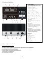
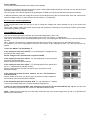
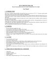
5. Controls and Indicators
1. Power Switch.
Turns power supply ON or OFF
2. Ammeter Display
Indicates output current
3. Voltmeter Display
Indicates output voltage
4. Output "+" Terminal (RED)
Positive polarity output terminal
5. Output "-" Terminal (BLACK)
Negative polarity output terminal
6. Ground "GND" Terminal
(GREEN)
Ground terminal connected to
chassis
7. CC Display
Indicates the unit is in constant
current mode (Minute indicator
in Timed Programming).
8. CV Display
Indicates the unit is in constant
voltage mode (Second indicator
in Timed Programming).
9. KEYPAD
10. USB Interface
11. RS-485 Interface
12. FUSE
13. Mains Cable
6. Operating Instructions
6.1. General Operation Principle
This section contains a condensed overview of the unit. Read this section to quickly get started.
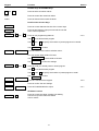
6.1.1. Getting Started with Keypad Functions
The front Keypad is organised and summarized as follow:
(1) Number Keys & UP/DOWN Keys
(2) 4 Dual Function Control Keys
-4-
Keypad
Function
Section
Number Keys & UP/DOWN Keys
0
thru 9
Press to select numerical values
▲ UP
Press to ascend the numerical values
▼ DN
Press to descend the numerical values
Dual Function Control Keys
SHIFT
Press to access alternate function of the control keys
CLEAR
PROG.
Press to terminate any input process and the unit will
exit to normal operation
0
thru
9
Press to use programming features.
Use 0
to recall the timed program
Use 1 thru
Use
SHIFT
USB/RS-485
4.4.2
9
ENTER
to specify the location of preset program to be stored
to confirm
Press to enter the PC interface selection menu.
You can choose either USB or RS-485
USB/RS-485
Use
to select USB or RS-485
Use
RECALL
0
thru
9
ENTER
Press to recall your stored preset or timed program
Use
0
Use 1
Use
SHIFT
Lock/Unlock
ENTER
SHIFT
to confirm the settings
to recall the timed program
thru 9
ENTER
to specify the location of preset program to recall
to confirm
Press to Lock/Unlock the Keypad
Press to confirm the new settings
O/P on/off
Press to Enable/Disable the output
SPECIAL Function
SHIFT
4.3.2
0
Press to access the Upper Voltage Limit Setting
Use thru to input the numerical values
Use to confirm
-5-
4.3.1
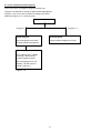
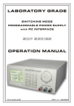
6.1.2. The Timed and Preset Programs
The unit can store 10 programs (program number 0-9).
Program 0 is reserved for storing 20 steps (timed subprograms).
Program 1 to 9 is for 9 sets of presets of voltage and current.
Please see Figure 5.1.2. for the structure.
Programming Features
Program 0
Program 1-9
Timed Program
Preset Program
The timed program can store
20 steps (timed subprograms)
9 sets of preset voltage and current
Time Subprogram
Each subprogram is capable
of storing 1 second to 99
minutes operation period.
The timed program can run
repeatly 1 to 999 cycles or
infinite cycles ("0")
Figure 5.1.2.
-6-
6.2. Standard Operation Mode
After switching on the unit, prior to any power being delivered, the unit will go through its start-up self-diagnostic routine.
As the unit carries out its diagnostic routine you will see both displays count from zero to nine.
The unit will now be in standard operation mode and will resume the voltage and ampere settings to those during
previous power down.
Warning !
For the above reason do not connect any equipment to the unit if you have any
doubt as to what its setting were at previous power down.
The unit will always maintain either the maximum set voltage or current within its capability. During operation either the
C.V. or C.C. indicator will be illuminated. These indicate whether the unit is running in constant voltage or constant
current mode respectively.
This unit has a built in O.V.P (over voltage protection) feature. In the event of the voltage becoming significantly greater
than the Upper Voltage Limit, the O.V.P. will be triggered. In this instance power delivery will be cut and an warning will
be displayed. When you get this warning, switch the unit off and remove all loadings.
If you then switch the unit back on it should resume normal operation.
In the event this problem persists, the unit must be returned to the agent for further investigation.
6.3. Setting of Operation Modes
6.3.1. Output On/Off Mode
1. Press SHIFT key.
The display will show .... ....
2. Press (O/P On/Off) key within 3 seconds.
3. Watch for the appearing “ ” in the display to confirm your setting, otherwise repeat the above procedures.
6.3.2. Lock/Unlock the keypad
1. Press SHIFT key.
The display will show .... ....
2. Press Lock/Unlock key within 3 seconds.
3. Press any number keypad and “LOC” will appear on the display.
This confirms keypad is locked otherwise repeat the above procedures
6.3.3. PC Interface USB/RS-485
1. Press SHIFT key.
The display will show .... ....
2. Press USB/485 key within 3 seconds.
3. Select desired PC Interface by pressing the UP or DN Key.
4. For USB, press ENTER to confirm setting.
5. For RS-485, enter 485 address followed by ENTER to confirm setting.
6.3.4. Upper Voltage Limit Setting
This feature limits the upper level setting of output voltage to prevent inadvertent setting of high output voltage which may
damage your equipment.
The value of this upper voltage range limit will be retained until further reset.
1.
2.
3.
4.
Press SHIFT and follow by 0 key.
The UP-L will appear in the display and enter your desired setting.
Enter your desired setting and press ENTER to confirm setting.
Recheck setting by repeating 1.
-7-
6.4. Manual Operation Mode
In manual operation mode, once the voltage and current have been set, the unit will maintain these settings until
reprogrammed.
There are two ways of setting up the unit in standard operation mode, either by manual operation or use of the preset
setting feature. Both methods are described below:6.4.1. Setting Voltage and Current by Manual Operation
1 Press ‘ENTER’ key
The left-hand display will show ‘S-E’ (i.e. set voltage) and the present voltage setting
will be shown in the right-hand display.
Set voltage to required level using either the number or up and down keys
(If you enter a voltage outside the unit’s capability, an error message will be
displayed followed by the maximum allowable voltage of the unit. You must re-enter
the voltage).
2 Press ‘ENTER’ key
The left-hand display will show ‘S-C’ (i.e. set current) and the present current setting
will be shown in the right-hand display.
Set the required current level using the keypad (If you enter a current level
larger than the units capability, an error message will appear followed by the
maximum allowable current of the unit. You must re-enter the required current)
3 Press ‘ENTER’ and the unit will immediately assume inputted settings.
The unit will now maintain these settings until it is in some way reprogrammed.
6.4.2. Using the Pre-set Feature
The unit has the ability to store nine pre-programmed voltage and current settings. Once programmed these settings will
be stored by the unit even when switched off.
PRE-SET PROGRAMMING
1 Press ‘PROG.’ key
The display will show ‘P- ’. Input the location of the pre-set (1 to 9) you wish to program.
2 The display will now show ‘P. ’ followed by the pre-set location you chose
and ‘ ’ (i.e. program pre-set voltage).
Using the keypad set your required voltage then press ‘ENTER’.
3 The display will now show ‘P.’, pre-set number, ‘C. ’ (i.e. program pre-set
current).
Set the required current level followed by the ‘ENTER’ key.
4 The unit will now ask you to set the next pre-set, i.e. ‘P ’, next pre-set, ‘E ’.
If you do not wish to change these settings press the ‘ENTER’ key and the unit will retain the current value and advance
to the next stage.
If you go through the above, up to the ninth pre-set, when you press ‘ENTER’, the pre-sets have now been successfully
programmed.
Whenever you want to terminate programming you can press the ‘CLEAR’ key to return to normal operation mode. The
programmed value for the preceding locations will be retained.
SELECTING PRE-SETS
1 Press ‘RECALL’ key
The left-hand display will show ‘L- ’.
2 Input the pre-set location you wish to use.
The unit will now display the setting for the chosen pre-set and both decimal places
will flash.
-8-
3 Press ‘ENTER’
The unit will immediately assume the chosen pre-set settings.
If during any of the above procedures you fail to input a setting within approximately ten seconds, the unit will cancel that
procedure and resume its previous settings.
You can exit any of the above operations by pressing the ‘CLEAR’ key and the unit will assume its previous setting.
In Manual Operation mode the voltage and current can be adjusted using the UP and DN keys within the units limits at
constant voltage mode (C.V.) and constant current mode (C.C.) respectively.
6.4.3. Using the Timed Programming
In the programmable mode the unit can be set to change the voltage and current settings for up to ten pre-set time
periods.
Once in the program mode, the unit will loop through the programmed settings for the previously entered cycles unless
interrupted by pressing ‘CLEAR’.
PROGRAMMING THE UNIT
This unit can be programmed to operate up to 20 timed subprograms ( GO to 19 ).
In the event you require to run 0 to 5 subprograms in the cycle, only set as 0 - 5 subprograms.
After which, set the time for the remaining subprogram to zero. Any subprogram with a time frame of zero will effectively
not exist.
Note – When the unit reaches an subprogram with a time frame of zero, it will return to the first subprogram (GO ).
For example if you set the subprogram 7 with zero time period, all the subprograms after 7 (i.e. 8,9,10) become nonexisted.
1 Press the ‘PROG.’ key followed by ‘0’.
2 The display will now show ‘GOOE’ (i.e. set subprogram 0 voltage) and any
previous pre-set voltage value.
Set the voltage to the required value and press ‘ENTER’.
3 The display will now show ‘GOOC ’ (i.e. set subprogram 0 current) and the
previously programmed value.
Set the current level and press ‘ENTER’.
4 The display will now show ‘GOOt ’ (i.e. set subprogram 0 time period) and
the ‘C.C.’ will illuminate to indicate minutes.
Set the number of whole minutes you require (up to a maximum of 99)
and press ‘ENTER’.
5 The display will remain as before, however, the ‘C.V.’ will illuminate to
indicate seconds.
Set the number of seconds you require (up to a maximum of 59) in addition to
the previously set minutes and press ‘ENTER’.
6 The left-hand display will now show ‘G IE ’ (i.e. set subprogram 1 voltage).
You must now repeat steps 2 to 5 for all 9 remaining subprograms.
7 After you have pressed ‘ENTER’, after setting the seconds for the twentieth address (No. 19), the unit has now
been successfully programmed and will return to standard operation mode.
NOTE : Please be aware that the life of the relay will limit the life of the power supply which is 100 X 10 operations as
stated by the manufacturer.
-9-
RUNNING THE TIMED PROGRAM CYCLES
Once all the subprograms have been filled, as explained in the previous section, to recall the program:
1 Press ‘RECALL’ followed by the ‘0’ key.
The display will show ‘rOOE’ (recalled subprogram 0 voltage) with the corresponding
value for subprogram 0.
Using the up and down keys you are now able to move up and down to check all four
values for all ten subprograms.
2 Once you are satisfied that all the subprograms are correct, press ‘ENTER’.
The display will show ‘run ’ and ‘000 ’.
Using the up and down keys set the number of cycles you require (0-999, 0 being
infinity).
3 Once the number of cycles is set press ‘ENTER’.
The unit will run through the program starting with subprogram 0.
You will know the unit is in running-in programmed mode as a dot on the extreme bottom right of the right hand display
will flash.
In order to exit the program, press the CLEAR button. The unit will resume in the standard operation mode. The voltage
and current settings will be those of the address the unit was up to at the point of exit from the program.
If during any of the above procedures you fail to input a setting within approximately ten seconds, the unit will cancel that
procedure and assume its previous settings.
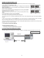
7. PC Interface Control User Manual
This section shows how to connect:
– Single power supply via USB1.0 Interface
– 2 or above(up to 31) power supplies via RS-485 Interface
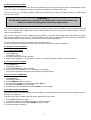
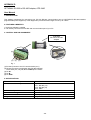
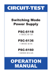
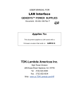
7.1. Connect a Single Power Supply to PC via USB1.0
The power supply can be connected to PC via USB1.0 as Figure 7.1a. Please use the provided USB connection cable.
Connect the USB cable to
the USB port at rear panel
5
USB-cable
5 m max.
Fig. 7.1a
-10-
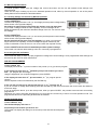
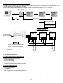
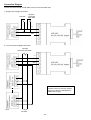
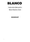
7.2. Connect Multiple Power Supplies to PC via RS-485
For multiple power supplies, use the RS-485 Interface through the RS-485 port at rear panel of the power supply. Up to
31 power supplies can be connected via RS-485.
You will need a RS-232 to RS-485 Adapter (optional accessory ) and the connection is as Fig. 7.2a & 7.2b.
RS-232 to RS-485
Adapter
10 m
1000 m max.
Fig. 7.2a
RS-232 connection
RS-485 connection
RS-485 Connector
1
GND B- A+
Connect to PC´s
RS-232 C port
2
GND B- A+
3
GND B- A+
NOTE
Please connect the provided 120
Ohm resistor across +A and –B of
the first and last power supplies.
Figure 7.2b
7.3. PC Application Software
7.3.1. What the application software will do
The application software can perform:
– Timed Programming
– Preset Programming
– Data logging
– Voltage, current and Upper voltage limit setting
7.3.2. System Requirements
–
–
–
–
CPU 450 Mhz or above
128 MB Ram
Min. monitor screen resolution: 800 x 600 pixels.
Operating systems: Windows® XP, ME, 2000, 98SE, 98
All brand or trade names are trademarks or registered trademarks of their respective companies.
-11-
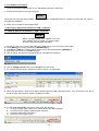
7.3.3. Installation of software
1. Place the provided installation disc in your CD ROM Drive and run setup.exe.
2. Follow the instructions in the setup program.
NOTE
During the running of the setup program, you may encounter “VERSION CONFICT” remarks, ignore it and click “YES” to
complete the installation.
3. A NDP icon is created in the Program Menu.
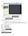
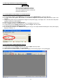
7.4 Running the Application Software for USB 1.0 Interface
7.4.1 Getting Started with Software for USB 1.0 Interface
NOTE
Before running the application software, you must
have installed and connected your power supply
to the PC using the provided USB cable.
1.
2.
3.
4.
5.
Ensure your PC is off ,connect USB cable to the USB plug of your PC and the power supply.
Press [SHIFT] then quickly followed by [USB/RS-485] key.
Use [UP] and [DN] key to select USB as shown in the LCD and followed by [ENTER] key.
Switch on your PC and run the NDP program.
Click on Setup, and select the desired USB port. The default is USB port 1.
Fig. 7.4a
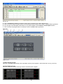
6. Click on Supply Connect, then click on Single in the drop menu.
7. An “Internal Timed Program” window as shown in Figure 7.4b will appear.
Fig. 7.4b
8. When the right bottom corner of the display window shows the UVL value(see Figure. 74c), connection to the PC is
made correctly and the power supply is operating normally.
Fig. 7.4c
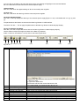
9. If it shows No Connection (see Figure 74d), check the following:
A. Go back to setup check if the correct USB/COM port has been assigned.
B. Check the Power Supply if USB has been selected.
C. Check the USB cable connections.
D. Check the power supply is ON.
Fig. 7.4d
-12-
Remarks:
Fig. 7.4e
(1)
Setting ------- one click , then the pop-up
Data Log Sampling Time
You can input your desired sample time from 1 second up or select from the drop menu.
Voltage Upper Limit Setting
You can set your output voltage upper limit value to further safeguard your low voltage applications.
(2)
Data Log window
A)
You can use the Data Log window to view present output data or stored data.
B)
All the parameters at the bottom of the window display can be changed by direct entry from the PC (with
decimal point) and then confirm by the Enter key of the PC , or select the values from respective drop
menu.
Parameters at the bottom of the Data Log window:
V Min. ------V Max. ------C Min. ------C Max. ------W Min. ------W Max. -------
Minimum voltage level.
Maximum voltage level.
Minimum current level.
Maximum current level.
Minimum power level in watt.
Maximum power level in watt.
(3) Log Name -------
Untile
▼
Click cursor on “Untitle” , type in a name for your log.
Note how the ###(5) icon changes to solid colour
(4) Log Description
You can type in your detail description of your log.
-13-
(5) ###Save Log
(a) This function (and the icon) becomes effective when a Log Name is entered to replace the “Untitle”.
(b) Click on it will save the current data onto the PC.
(c) To retrieve the data , go to the drop menu at (3) Log Description.
(6) ##### Export to a file of xls type
Click on this icon will export the collected data (in the Save Log) in xls format to your PC.
(7) XXX Delete
Click on this icon will delete the current log or retrieved log on display at (3).
(8) Print Log in xls format.
(9) Time minimum and Time Length
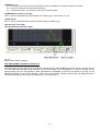
Fig. 7.4f
Bottom part of data log window
THE TIME FRAME CONCEPT OF DATA LOG
The data logging function starts when the software is started running. When T Min is set to zero second, it means the unit
is on real time and the length of time lapsed is on the left hand side of the Time Minimum. T Len is the length of time
lapsed starting from the Time Minimum. Both parameters are adjustable so that any time period of the log can be
displayed for analysis. In the above example, T Min is set to 0 second and T length to 120 second, the display shows the
output data starting at 0 second ago and ending at the 120 second mark.
-14-
7.4.2. General Operation
Please refer to Figure 7.4g for the following description.
Figure 7.4g
(10) Power Supply Description:
Test00
You may click on and assign an Description for your power supply in use.
Actually this feature is mainly for multiple power supplies application with RS-485.
(11) Power Supply Address :
00
▼
This function is for multiple power supplies application. Each power supply has a unique address. Ignore this function
when using USB.
(12) Location:
Workshop 1
You may click on and assign an identification for your power supply in use. Actually this feature is mainly for multiple
power supplies application with RS-485.
(13) Voltage:
##.V
Enter the desired output voltage with decimal point.
-15-
(14) Current:
#.## A
Enter the desired current limit with decimal point.
(15) OUTPUT o------o
Left click on icon will switch on or off the output.
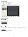
7.4.3. Internal Timed Program
The PC interface remote mode really eliminates the tedious process in keying in groups of entries on the power supply.
Because all the data are displayed together in the monitor, possibility of wrong entry is greatly reduced. Data of different
groups can be classified, stored, exported and retrieved for use at any time.
Furthermore, retrieved data will be in red colour if they exceed the present preset limits of voltage in upper voltage level
or current limiting value.
The operation principle of Saving, Exporting, Filing, Deleting and Printing are the same as the Data Log function.
Clear Table
Save to PS
Read fro PS
Run
-----------------------------
Delete all data on the Display Table to ready for new data entry.
Transfer data from the Display Table to the Power Supply.
Get data from the Power Supply.
To run the timed program.
7.4.4. External Timed Program
External Timed Program is different from the Internal Timed Program. External Timed Program is completely controlled by
PC, PC counts the time and changes voltage and current of power supply. Internal Timed Program is using built-in
function of the power supply.
Select External Timed Program tap to switch to the External Timed Program Page.
Select number of steps for the program: Enter the number of steps in the field of No. of Rows and press Enter
(Maximum 100 Steps)
The operation principle of Saving, Exporting, Filing, Deleting and Printing are the same as the Data Log function.
Clear Table
Run
---------------------
Delete all data on the Display Table to ready for new data entry.
To run the timed program.
7.4.5. Internal Preset Memory
The operation principle is the same as Internal Timed Program.
To activate the selected preset click on the box of the option column then click Run.
-16-
7.5. Running the Software using RS-485 Interface
NOTE
Before running the application software,
you must have installed and connected
your power supplies to the PC via RS-485
as Figure 7.2a and 7.2b.
7.5.1. Getting Started with Software for RS-485 Interface
1. On your power supplies, press [SHIFT] key, then quickly press [USB/RS-485] key and select RS-485.
2. A 2-digit number will appear. This number is the address assigned to the power supply and will be used in the
software.
3. Using the Key Pad to key in the address to assign for each power supply. The range is 00 ~ 30 and each of the power
supplies requires an unique address.
4. Switch on your PC and run the NDP program.
5. Click on Setup, and select the desired Com. Port. The default is set at Com 1.
6. In the tool bar, Click on Supply Connect, then click on Single in the drop menu.
7. An Internal Timed Program window will appear.
8. By choosing the address in the Address field (Figure 7.5a) you can input the desired settings for each power supply
as given in Section 7.2.
Fig. 7.5a
7.5.2. Configuration of Multi Windows Analysis
1. In the tool bar, Click on Supply Connect, then click on Multi in the drop menu.
2. A Multi Windows window (Figure. 7.5.1a) will appear.
3. Click on the icon (circled as below), a Multi Power Supply Connect Setup (Figure 7.5.1b) will appear.
Fig. 7.5.1a
-17-
Fig. 7.5.1b
4.
5.
6.
7.
Click on AutoScan Connect, the window will show the connected power supply indicted as “Y”.
Click on the box along the Visible Column to set the desired power supply to be visible in Multiple Data Log Window.
You can type in the description and location of your power supplies in the Location and Description Column.
Click on Close icon(at right bottom of window) to return to Multiple Data Log Window.
Remarks:
Figure 7.5.1c
(1) Multi Alleyway Display
One click, it will display the Data log and output data of all the power supplies. It will activate the icon (2), (3) and (4).
(2) Show Digital and Log
One click, it will show both the data log of all the connected power supplies.
-18-
You can click on the data log to select the power supply, the data log will highlight in blue and the address
bar in the left bottom window will show the selected power supply.
(3) Show Digital
One click, it will show the digital readings of all the connected power supplies.
(4) Show Log
One click, it will show the data log of all the connected power supplies.
(5) Single Alleyway Display
One click, it will only display the data log of the selected power supply(Figure 7.5.1d). It will disable the icon (2), (3) and
(4).
The parameters at the bottom are same as the Data Log Window in USB Interface.
The All SP Tick box --- Tick to apply the parameters to all Data Log Window in Multi Alleyway Display.
(6) Log Thumbnails Size Setup
One click, it let user to adjust the window size of the Data log Window in Multi Alleyway Display.
Use the sliders to adjust the height and width of the Data Log Windows.
Scale 4:3 tick box can enable 4:3 screen size for the Data Log Windows.
(7) (8) (9) (10) (11) (12)
Fig. 7.5.1e
#
(7)
(8)
(9)
(10)
(11)
(12)
(13)
(14)
(15)
(16)
Icon
Save Log
(13)
(14)
(15)
(16)
Description
a) Click on it and save log window (Fig. 11) will appear
b) Click on the box along the Save column to choose the desired power supplies´
data log to save.
c) Type in the Table Name.
d) Click save will save the current data onto the PC
e) To retrieve data, go to the drop menu at Log (13)
Delete Log
It can delete the log data in the PC
Export to a file log of xls type Click on this icon will export the collected data (in Data Log) in xls format to your PC.
Open file Log of xls type
Click on this icon will import the collected data in xls format file to the NPD software
Close file Log of xls type
Click on this icon will close the import xls format file.
Print Log
Print Log in xls format.
Log
Click on it to select the save log data.
Sample
Click on it to select the sampling time.
SetV
Click on it and type in to change the voltage setting of the selected power supply.
SetC
Click on it and type in to change the current setting of the selected power supply.
-19-
8. Maintenance
WARNING !
This is a factory sealed unit and the only maintenance that can be carried out is described
below. You should under no circumstances remove any of the casing from the unit. In case that
you encounter problems which cannot be solved using the methods described below then the whole
unit must be returned to the agent.
8.1. Fuse Replacement
If the fuse blows, the unit will not operate. Under normal circumstances the fuse should not blow, hence if it does this may
indicate some problem with the unit.
Before replacing the fuse, remove any loading from the unit and then only replace with a fuse of the correct rating.
8.2. Recalibration
This in-case recalibration is to reduce:
1. The difference between set value and the actual output value from the output terminal. (see section 7.3)
Note: You only do section 7.3 when the difference is greater than 0.1V for voltage and 0.01A for current
2. The difference between set value and the LED Display value. (see section 7.4)
Note: You only do section 7.4 when the difference is greater than 0.1V for voltage and 0.01A for current
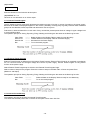
8.3. Recalibrating the Set Value and the Actual Output Value
8.3.1. Calibrating Voltage
1 Connect a voltmeter to the output terminals (see fig. 1).
2 Set the voltage and current value as follow:
Set voltage value
Set current value
15.0 V
1,50 A
3 Compare the voltmeter reading with the set voltage value.
4 Calculate : Difference = Set Value – Voltmeter reading.
5 Use the calculated difference to find the corresponding offset value on the look up table for voltage calibration in
appendix A.
6 Press on the keypad in the sequence: “SHIFT” -> “3” -> “9”.
This will gain you access to the calibration mode and the display will show ‘CAL A-d ’.
7 Using the up and down keys to select (d-A) and press ‘ENTER’.
This will gain you access to calibrate the difference between set value and the actual output value.
8 The display will show “d-A ----E” and press “ENTER”.
9 The display will show “Ad-E OFSt ” and press “ENTER”.
10 Key in the offset value you find on the look up table and press “ENTER”.
11 If you press ‘CANCEL’ at any time during calibration you will jump out the calibration process and
no change will be made to the memory.
8.3.2. Calibrating Current
1 Prepare an ammeter and make sure it can measure up to 5A.
Connect the ammeter to the unit(see fig. 2).
2 Set the voltage and current value as follow:
Set voltage value
Set current value
15.0 V
1.50 A
3 Compare the ammeter reading with the set current value.
4 Calculate : Difference = Set Value – ammeter reading.
5 Use the calculated difference to find the corresponding offset value on the look up table for current calibration in
appendix B.
6 Press on the keypad in the sequence: “SHIFT” -> “3” -> “9”.
This will gain you access to the calibration mode and the display will show ‘CAL A-d’ .
7 Using the up and down keys to select (d-A) and press ‘ENTER’.
This will gain you access to calibrate the difference between set value and the actual output value.
8 The display will show “d-A --C ” and press “ENTER”.
-20-
9 The display will show “Ad-E OFSt” and press “ENTER”.
10 Key in the offset value you find on the look up table and press “ENTER”.
11 If you press ‘CANCEL’ at any time during calibration you will jump out the calibration process and no
change will be made to the memory.
8.4. Recalibrating the Set Value and the LED Display Value
8.4.1. Calibrating Voltage
1 Set the voltage and current value as follow:
Set voltage value
Set current value
15.0 V
1.50 A
2 Compare the voltmeter reading with the set voltage value.
3 Calculate : Difference = Set Value – Voltmeter reading.
4 Use the calculated difference to find the corresponding offset value on the look up table for voltage calibration in
appendix A.
5 Press on the keypad in the sequence: “SHIFT” -> “3” -> “9”.
This will gain you access to the calibration mode and the display will show ‘CAL A-d’ .
6 Using the up and down keys to select (A-d) and press ‘ENTER’.
This will gain you access to calibrate the difference between set value and the actual output value.
7 The display will show “A-d ---E” and press “ENTER”.
8 The display will show “Ad-E OFSt” and press “ENTER”.
9 Key in the offset value you find on the look up table and press “ENTER”.
10 If you press ‘CANCEL’ at any time during calibration you will jump out the calibration process and no change will be
made to the memory.
8.4.2. Calibrating Current
1 Set the voltage and current value as follow:
Set voltage value
Set current value
15.0 V
1.50 A
2 Compare the ammeter reading with the set current value.
3 Calculate : Difference = Set Value – ammeter reading.
4 Use the calculated difference to find the corresponding offset value on the look up table for current calibration in
appendix B.
5 Press on the keypad in the sequence: “SHIFT” -> “3” -> “9”.
This will gain you access to the calibration mode and the display will show “CAL A-d” .
6 Using the up and down keys to select (A-d) and press ‘ENTER’.
This will gain you access to calibrate the difference between set value and the actual output value.
7 The display will show “A-d ---C” and press “ENTER”.
8 The display will show “Ad-E OFSt” and press “ENTER”.
9 Key in the offset value you find on the look up table and press “ENTER”.
10 If you press ‘CANCEL’ at any time during calibration you will jump out the calibration process and no change will be
made to the memory.
-21-
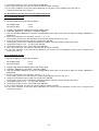
APPENDIX A
LOOK UP TABLE FOR VOLTAGE RECALIBRATION
Difference
Offset
Difference
Offset
Difference
Offset
Difference
Offset
+ 0.00
0 or 127
+ 0.33
33
+ 0.66
66
+ 0.99
99
+ 0.01
1
+ 0.34
34
+ 0.67
67
+ 1.00
100
+ 0.02
2
+ 0.35
35
+ 0.68
68
+ 1.01
101
+ 0.03
3
+ 0.36
36
+ 0.69
69
+ 1.02
102
+ 0.04
4
+ 0.37
37
+ 0.70
70
+ 1.03
103
+ 0.05
5
+ 0.38
38
+ 0.71
71
+ 1.04
104
+ 0.06
6
+ 0.39
39
+ 0.72
72
+ 1.05
105
+ 0.07
7
+ 0.40
40
+ 0.73
73
+ 1.06
106
+ 0.08
8
+ 0.41
41
+ 0.74
74
+ 1.07
107
+ 0.09
9
+ 0.42
42
+ 0.75
75
+ 1.08
108
+ 0.10
10
+ 0.43
43
+ 0.76
76
+ 1.09
109
+ 0.11
11
+ 0.44
44
+ 0.77
77
+ 1.10
110
+ 0.12
12
+ 0.45
45
+ 0.78
78
+ 1.11
111
+ 0.13
13
+ 0.46
46
+ 0.79
79
+ 1.12
112
+ 0.14
14
+ 0.47
47
+ 0.80
80
+ 1.13
113
+ 0.15
15
+ 0.48
48
+ 0.81
81
+ 1.14
114
+ 0.16
16
+ 0.49
49
+ 0.82
82
+ 1.15
115
+ 0.17
17
+ 0.50
50
+ 0.83
83
+ 1.16
116
+ 0.18
18
+ 0.51
51
+ 0.84
84
+ 1.17
117
+ 0.19
19
+ 0.52
52
+ 0.85
85
+ 1.18
118
+ 0.20
20
+ 0.53
53
+ 0.86
86
+ 1.19
119
+ 0.21
21
+ 0.54
54
+ 0.87
87
+ 1.20
120
+ 0.22
22
+ 0.55
55
+ 0.88
88
+ 1.21
121
+ 0.23
23
+ 0.56
56
+ 0.89
89
+ 1.22
122
+ 0.24
24
+ 0.57
57
+ 0.90
90
+ 1.23
123
+ 0.25
25
+ 0.58
58
+ 0.91
91
+ 1.24
124
+ 0.26
26
+ 0.59
59
+ 0.92
92
+ 1.25
125
+ 0.27
27
+ 0.60
60
+ 0.93
93
+ 1.26
126
+ 0.28
28
+ 0.61
61
+ 0.94
94
+ 1.27
127
+ 0.29
29
+ 0.62
62
+ 0.95
95
+ 0.30
30
+ 0.63
63
+ 0.96
96
+ 0.31
31
+ 0.64
64
+ 0.97
97
+ 0.32
32
+ 0.65
65
+ 0.98
98
-22-
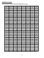
APPENDIX A (Continue)
LOOK UP TABLE FOR VOLTAGE RECALIBRATION (Continue)
Difference
Offset
Difference
Offset
Difference
Offset
Difference
Offset
- 0.01
129
- 0.34
162
- 0.67
195
- 1.00
228
- 0.02
130
- 0.35
163
- 0.68
196
- 1.01
229
- 0.03
131
- 0.36
164
- 0.69
197
- 1.02
230
- 0.04
132
- 0.37
165
- 0.70
198
- 1.03
231
- 0.05
133
- 0.38
166
- 0.71
199
- 1.04
232
- 0.06
134
- 0.39
167
- 0.72
200
- 1.05
233
- 0.07
135
- 0.40
168
- 0.73
201
- 1.06
234
- 0.08
136
- 0.41
169
- 0.74
202
- 1.07
235
- 0.09
137
- 0.42
170
- 0.75
203
- 1.08
236
- 0.10
138
- 0.43
171
- 0.76
204
- 1.09
237
- 0.11
139
- 0.44
172
- 0.77
205
- 1.10
238
- 0.12
140
- 0.45
173
- 0.78
206
- 1.11
239
- 0.13
141
- 0.46
174
- 0.79
207
- 1.12
240
- 0.14
142
- 0.47
175
- 0.80
208
- 1.13
241
- 0.15
143
- 0.48
176
- 0.81
209
- 1.14
242
- 0.16
144
- 0.49
177
- 0.82
210
- 1.15
243
- 0.17
145
- 0.50
178
- 0.83
211
- 1.16
244
- 0.18
146
- 0.51
179
- 0.84
212
- 1.17
245
- 0.19
147
- 0.52
180
- 0.85
213
- 1.18
246
- 0.20
148
- 0.53
181
- 0.86
214
- 1.19
247
- 0.21
149
- 0.54
182
- 0.87
215
- 1.20
248
- 0.22
150
- 0.55
183
- 0.88
216
- 1.21
249
- 0.23
151
- 0.56
184
- 0.89
217
- 1.22
250
- 0.24
152
- 0.57
185
- 0.90
218
- 1.23
251
- 0.25
153
- 0.58
186
- 0.91
219
- 1.24
252
- 0.26
154
- 0.59
187
- 0.92
220
- 1.25
253
- 0.27
155
- 0.60
188
- 0.93
221
- 1.26
254
- 0.28
156
- 0.61
189
- 0.94
222
- 1.27
255
- 0.29
157
- 0.62
190
- 0.95
223
- 0.30
158
- 0.63
191
- 0.96
224
- 0.31
159
- 0.64
192
- 0.97
225
- 0.32
160
- 0.65
193
- 0.98
226
- 0.33
161
- 0.66
194
- 0.99
227
7
-23-
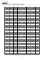
APPENDIX B
LOOK UP TABLE FOR CURRENT RECALIBRATION
Difference
Offset
Difference
Offset
Difference
Offset
Difference
Offset
+ 0.000
0 or 127
+ 0.033
33
+ 0.066
66
+ 0.099
99
+ 0.001
1
+ 0.034
34
+ 0.067
67
+ 0.100
100
+ 0.002
2
+ 0.035
35
+ 0.068
68
+ 0.101
101
+ 0.003
3
+ 0.036
36
+ 0.069
69
+ 0.102
102
+ 0.004
4
+ 0.037
37
+ 0.070
70
+ 0.103
103
+ 0.005
5
+ 0.038
38
+ 0.071
71
+ 0.104
104
+ 0.006
6
+ 0.039
39
+ 0.072
72
+ 0.105
105
+ 0.007
7
+ 0.040
40
+ 0.073
73
+ 0.106
106
+ 0.008
8
+ 0.041
41
+ 0.074
74
+ 0.107
107
+ 0.009
9
+ 0.042
42
+ 0.075
75
+ 0.108
108
+ 0.010
10
+ 0.043
43
+ 0.076
76
+ 0.109
109
+ 0.011
11
+ 0.044
44
+ 0.077
77
+ 0.110
110
+ 0.012
12
+ 0.045
45
+ 0.078
78
+ 0.111
111
+ 0.013
13
+ 0.046
46
+ 0.079
79
+ 0.112
112
+ 0.014
14
+ 0.047
47
+ 0.080
80
+ 0.113
113
+ 0.015
15
+ 0.048
48
+ 0.081
81
+ 0.114
114
+ 0.016
16
+ 0.049
49
+ 0.082
82
+ 0.115
115
+ 0.017
17
+ 0.050
50
+ 0.083
83
+ 0.116
116
+ 0.018
18
+ 0.051
51
+ 0.084
84
+ 0.117
117
+ 0.019
19
+ 0.052
52
+ 0.085
85
+ 0.118
118
+ 0.020
20
+ 0.053
53
+ 0.086
86
+ 0.119
119
+ 0.021
21
+ 0.054
54
+ 0.087
87
+ 0.120
120
+ 0.022
22
+ 0.055
55
+ 0.088
88
+ 0.121
121
+ 0.023
23
+ 0.056
56
+ 0.089
89
+ 0.122
122
+ 0.024
24
+ 0.057
57
+ 0.090
90
+ 0.123
123
+ 0.025
25
+ 0.058
58
+ 0.091
91
+ 0.124
124
+ 0.026
26
+ 0.059
59
+ 0.092
92
+ 0.125
125
+ 0.027
27
+ 0.060
60
+ 0.093
93
+ 0.126
126
+ 0.028
28
+ 0.061
61
+ 0.094
94
+ 0.127
127
+ 0.029
29
+ 0.062
62
+ 0.095
95
+ 0.030
30
+ 0.063
63
+ 0.096
96
+ 0.031
31
+ 0.064
64
+ 0.097
97
+ 0.032
32
+ 0.065
65
+ 0.098
98
-24-
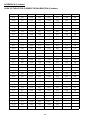
APPENDIX B (Continue)
LOOK UP TABLE FOR CURRENT RECALIBRATION (Continue)
Difference
Offset
Difference
Offset
Difference
Offset
Difference
Offset
- 0.01
129
- 0.34
162
- 0.67
195
- 1.00
228
- 0.02
130
- 0.35
163
- 0.68
196
- 1.01
229
- 0.03
131
- 0.36
164
- 0.69
197
- 1.02
230
- 0.04
132
- 0.37
165
- 0.70
198
- 1.03
231
- 0.05
133
- 0.38
166
- 0.71
199
- 1.04
232
- 0.06
134
- 0.39
167
- 0.72
200
- 1.05
233
- 0.07
135
- 0.40
168
- 0.73
201
- 1.06
234
- 0.08
136
- 0.41
169
- 0.74
202
- 1.07
235
- 0.09
137
- 0.42
170
- 0.75
203
- 1.08
236
- 0.10
138
- 0.43
171
- 0.76
204
- 1.09
237
- 0.11
139
- 0.44
172
- 0.77
205
- 1.10
238
- 0.12
140
- 0.45
173
- 0.78
206
- 1.11
239
- 0.13
141
- 0.46
174
- 0.79
207
- 1.12
240
- 0.14
142
- 0.47
175
- 0.80
208
- 1.13
241
- 0.15
143
- 0.48
176
- 0.81
209
- 1.14
242
- 0.16
144
- 0.49
177
- 0.82
210
- 1.15
243
- 0.17
145
- 0.50
178
- 0.83
211
- 1.16
244
- 0.18
146
- 0.51
179
- 0.84
212
- 1.17
245
- 0.19
147
- 0.52
180
- 0.85
213
- 1.18
246
- 0.20
148
- 0.53
181
- 0.86
214
- 1.19
247
- 0.21
149
- 0.54
182
- 0.87
215
- 1.20
248
- 0.22
150
- 0.55
183
- 0.88
216
- 1.21
249
- 0.23
151
- 0.56
184
- 0.89
217
- 1.22
250
- 0.24
152
- 0.57
185
- 0.90
218
- 1.23
251
- 0.25
153
- 0.58
186
- 0.91
219
- 1.24
252
- 0.26
154
- 0.59
187
- 0.92
220
- 1.25
253
- 0.27
155
- 0.60
188
- 0.93
221
- 1.26
254
- 0.28
156
- 0.61
189
- 0.94
222
- 1.27
255
- 0.29
157
- 0.62
190
- 0.95
223
- 0.30
158
- 0.63
191
- 0.96
224
- 0.31
159
- 0.64
192
- 0.97
225
- 0.32
160
- 0.65
193
- 0.98
226
- 0.33
161
- 0.66
194
- 0.99
227
-25-
Appendix C
Command Set
{ }- command data, [ ] - return data, [OK] = "OK", [CR] = 0dh
???? = 30h, 30h, 30h, 30h - 39h, 39h, 39h, 39h (4 bytes data)
??? = 30h, 30h, 30h - 39h, 39h, 39h (3 bytes data)
?? = 30h, 30h – 39h, 39h (2 bytes data)
<address> 30h, 30h - 3fh, 3fh (2 bytes data).
BLUE – Input Command
RED – Return Data from Power Supply
PS = Power Supply
Command Code
Description
Input Command: SESS <address> <CR>
Disable front panel
keypad and make PS to
Remote Mode
Return Data from Power Supply: [OK] [CR]
Input Command: ENDS <address> <CR>
Enable front panel keypad
and make PS to exit
Remote Mode
Return Data from Power Supply: [OK] [CR]
Input Command:
CCOM <address> <RS> {000-255} <CR>
Change USB1.1/RS485
<RS> = 0 -> USB1.1
<RS> = 1 -> RS-485
Return Data from Power Supply:
[OK] [CR]
Input Command:
GCOM <address> <CR>
Get the RS-485 address
Return Data from Power Supply:
[RS] RS485 Address [??] [CR]
[OK] [CR]
Get maximum voltage
and current of PS
Input Command:
GMAX <address> <CR>
Return Data from Power Supply:
Voltage [???] Current [???] [CR]
[OK] [CR]
Get Upper Voltage
Limit of PS
Input Command:
GOVP <address> <CR>
Return Data from Power Supply:
Voltage [???] [CR]
[OK] [CR]
Input Command:
GETD <address> <CR>
Get Voltage & Current
reading from PS
Return Data from Power Supply:
Voltage [????] Current [????] [0] [CR][OK]
Voltage [????] Current [????] [1] [CR][OK]
[CR]
[CR]
PS in CV mode
PS in CC mode
Get Voltage & Current
Set Value from PS
Input Command:
GETS <address> <CR>
Return Data from Power Supply:
Voltage [???] Current [???] [CR]
[OK] [CR]
-26-
Command Code
Description
Get All Preset
Memory
Values from PS
Input Command:
GETM <address> <CR>
Return Data from Power Supply:
Memory 1 Voltage [???] Current [???] [CR]
Memory 2 Voltage [???] Current [???] [CR]
.
.
.
.
.
.
.
.
.
.
.
.
.
.
.
Memory 9 Voltage [???] Current [???] [CR]
[OK] [CR]
Input Command:
GETM <address> location {1-9} <CR>
Get Memory from
Specific Preset of
PS
Get all the Timed
Program Memory of
PS
Return Data from Power Supply:
Voltage [???] Current [???] [CR] [OK] [CR]
Input Command:
GETP <address> <CR>
Return Data from Power Supply:
Program 00 Voltage [???] Current [???] Minute [??]Second [??] [CR]
Program 01 Voltage [???] Current [???] Minute [??]Second [??] [CR]
.
.
.
.
.
.
.
.
.
.
.
.
.
.
.
.
.
.
.
.
.
Program 19 Voltage [???] Current [???] Minute [??] Second [??][CR]
[OK] [CR]
Input Command:
GETP <address> program {00-19} <CR>
Return Data from Power Supply:
Voltage [???] Current [???] Minute [??] Second [??][CR]
[OK] [CR]
Input Command:
VOLT <address> voltage {000-XXX} <CR>
Get Timed Program
Memory from
Specific Program of
PS
Set Voltage Level
XXX-Max. Output
Rating Voltage =
XX.X V Current =
X.XX V
Set Current Level
Return Data from Power Supply:
[OK] [CR]
Input Command:
CURR <address> current {000-XXX} <CR>
Return Data from Power Supply:
[OK] [CR]
Set Upper Voltage
Limit of PS
Input Command:
SOVP <address> voltage {000-XXX} <CR>
Return Data from Power Supply:
[OK] [CR]
Disable Output of
PS
Input Command:
SOUT <address> 1 <CR>
Return Data from Power Supply:
[OK] [CR]
Enable Output of
PS
Input Command:
SOUT <address> 0 <CR>
Return Data from Power Supply:
[OK] [CR]
-27-
Command Code
Description
Input Command:
PROM <address> location {1-9} Voltage {000-XXX} Current {000-XXX} <CR>
Return Data from Power Supply:
[OK] [CR]
Input Command:
PROP <address> location {00-19} Voltage {000-XXX} Current {000-XXX}
Minute {00-99} Second {00-59} <CR>
Return Data from Power Supply:
[OK] [CR]
Input Command:
RUNM <address> location {1-9} <CR>
Set Voltage and
Current values of
Preset Memory
Set Voltage,
Current and Time
period of Timed
Program
Recall Preset
Memory
1-9
Return Data from Power Supply:
[OK] [CR]
Input Command:
RUNP <address> times {000-999} <CR>
Run Timed Program
(000 = run infinite
times)
Stop Timed
Program
Return Data from Power Supply:
[OK] [CR]
Input Command:
STOP <address> <CR>
Return Data from Power Supply:
[OK] [CR]
-28-
APPENDIX D
OPTIONAL RS-232 to RS-485 Adapter; ATR-2485
User Manual
1. INTRODUCTION
This Adapter is designed for connecting your PC with RS-232 communication port to HALFDUPLEX RS-485 interface
programmable power supplies (or other equipment). Its transmission length can be up to 1000m.
2. FEATURES & BENEFITS
1. No driver software is needed
2. Can directly connected to male RS-232 communication port of your PC
3. CONTROL AND PIN ASSIGNMENT
ATR-2485
RS-232 to RS-485
Adapter
(2)
(1)
(3)
(4)
(5)
Fig. 1
(1) RS-232 (Connect to the PC communication port )
(2) RS-485 (Connect to equipment with RS-485 interface)
There are 6 pins, only A+, B- and GND pin are useful.
(3) Pin A+
(4) Pin B(5) Pin GND
4. SPECIFICATIONS
RS-232 side of the adapter
RS-485 side of the adaptor
Connection Speed
Transmission Length
Dimension
Weight
DB-9 female connector
3-pin connector
pin 1: RS-485 (+A)
pin 2: RS-485 (-B)
pin 3: GND
9600bps
Up to 1000 m
33mm (W) x 17mm (H) x 87mm (D)
40 g
-29-
Connection Diagram
Connect the RS-232 side of ATR-2485 to the PC Communication port.
1. Single Power Supply Connection
120 Ohm
120 Ohm
come with
ART-2485
A+
BGND
2. 2 or more power supplies connection:
120 Ohm
come with ATR-2485
A+
BGND
NOTE
Please connect a 120 Ohm resistor
across A+ and B- of the First and
Last power supply.
Fig. 3
120 Ohm
-30-