1
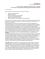
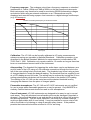
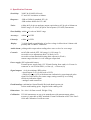
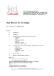
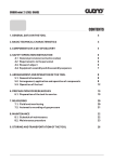
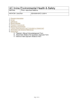
User Manual
JCI 140 Static Monitor
1. Introduction
2. The JCI 140 Static Monitor
3. Use of Instrument
4. Specification Features
WARNING
Please note that this equipment is not suitable for use where hazardous
flammable atmospheres are or may be present (hazardous areas as defined in IEC
60079-10-1 and IEC 60079-10-2 inside or outside the equipment). Furthermore,
even in the absence of designated hazardous areas, this equipment should not be
used in close proximity to flammable substances without first conducting a risk
assessment which is the responsibility of the end user company.
CE Conformance
Declaration of CE conformance
Chilworth Technology Ltd, Beta House, Southampton Science Park, Southampton.
SO16 7NS, UK declares, as designer and manufacturer of the JCI 140 Static Monitor,
that the design and construction of these instruments conform to the requirements of
the EC Directive on Electromagnetic Compatibility (EMC) 89/336/EEC to Standards EN
50081-1:1992 and EN 50082-1: 1992. These instruments also conform to the
requirements of the Electrical Equipment (Safety) Regulations 1994 (S.I. 1994/3260).
Dr Stephen Rowe, for and on behalf of Chilworth Technology Ltd.
RoHS and WEEE Directives
JCI Chilworth electrostatic measuring instruments are not required to conform to the
RoHS Directive because they come within Category 9 exemption.
To comply with the requirements of the EC WEEE (Waste Electrical & Electronic
Equipment) Directive all JCI Chilworth instruments, at the end of their useful life, should
be returned to Chilworth Technology Ltd for disposal or recycling in an environmentally
appropriate way. Chilworth Technology Ltd is a member of the Producer Compliance
Scheme ECONO-WEEE Ltd registration number WEE/KB1414VU.
PRODUCT WARRANTY
All test instrumentation supplied by Chilworth Technology Ltd., is manufactured to the highest
specification, and as such Chilworth Technology Ltd., warrants the product against defects in materials
and workmanship for a period of twelve (12) months from the date of receipt at the Customer premises,
on a return to base policy.
It is a necessary requirement of the warranty conditions that the instructions given in the user manual are
read, understood and adhered to before putting the instrumentation into first use. If any doubt exists, please
consult the manufacturer for further assistance. In such cases where the product is returned to Chilworth
Technology Ltd., we will inspect the product on receipt to diagnose the fault, and will issue the Customer with
an inspection and condition report.
If the product proves defective during the warranty period, Chilworth Technology Ltd., at its option, will
repair the product at our facilities in Southampton, UK.
Provided the product has been used in accordance with the manufacturers guidelines and that the fault is due
to a manufacturing defect or component failure and is not due to expected wear and tear caused by the
operating environment in which it is used, this warranty covers all parts and labour, but specifically excludes
any consumable parts supplied with the product and any shipping costs to Chilworth Technology Ltd.
Chilworth Technology Ltd. shall not be obliged under this warranty:
a)
b)
c)
d)
e)
f)
g)
h)
i)
j)
to repair damage resulting from attempts by personnel other than Chilworth Technology Ltd.
representatives to install, repair or service the product unless directed by a Chilworth Technology
Ltd. representative,
to repair damage, malfunction, or degradation of performance resulting from improper use or
connection to incompatible equipment or memory,
to repair damage, malfunction, or degradation of performance caused by the use of non Chilworth
Technology Ltd. supplies or consumables or the use of Chilworth Technology Ltd. supplies not
specified for use with the product,
to repair an item that has been modified or integrated with other products when the effect of such
modification or integration increases the time or difficulty of servicing the product or degrades
performance or reliability,
to perform user maintenance or cleaning or to repair damage, malfunction, or degradation of
performance resulting from failure to perform user maintenance and cleaning as prescribed in
published instruction/user manual,
to repair damage, malfunction, or degradation of performance resulting from use of the product in
an environment not meeting the operating specifications set forth in the instruction/user manual,
to repair damage, malfunction, or degradation of performance resulting from failure to properly
prepare and transport the product as prescribed in published product materials
to replace items that have been refilled, are used up, abused, misused, or tampered with in any
way;
to support software not supplied by Chilworth Technology Ltd.;
to provide software or firmware updates or upgrades.
In the maintenance of the product, Chilworth Technology Ltd. may use new or equivalent to new parts,
assemblies or products for equal or improved quality. All defective parts, assemblies, and products become
the property of Chilworth Technology Ltd.
Any additional service identified and provided by Chilworth Technology Ltd. at the Customer’s request shall
be invoiced to Customer at Chilworth Technology Ltd.’s current rates for parts, labour and travel.
User Manual
JCI 140 Static Monitor
The JCI 140 is a compact instrument for easy, sensitive
and reliable measurement and monitoring of electrostatic conditions
1. Introduction
Static electricity causes problems in many areas of industry:
•
•
•
•
•
•
ignition of flammable gases
shocks to personnel
attraction of airborne dust and debris
cling of thin films and light fabrics
damage to semiconductor devices
upset of operation of microelectronic system operation
Static electricity arises when materials in contact are separated and the speed of charge
movement on either surface and away to earth is long compared to the time for the
surfaces to move apart.
Many operations in industry and normal life involve the contact and separation of
materials that are poor or bad conductors of electricity - plastics are notable examples.
Common examples are the occurrence of sparks when combing the hair or taking off an
acrylic jumper, shocks when getting out of a car and shocks after walking across a
nylon carpet and touching earthed conductors. The separation of such surfaces is often
associated with retention of static charge. Voltages of several thousand volts (and up to
20kV) can be generated on our bodies as we go about normal daily activities. When we
touch a metal object and feel a shock or, for example, when we hear a crackle as we
take off an acrylic jumper we create an electrical discharge. This may give us a shock,
damage a microelectronic circuit or couple into the computer and upset computer
operation.
Manufacturing operations may involve the handling of thin sheet materials - for instance
in the printing and packaging industries. Static can cause sheets to stick together or be
attracted to nearby surfaces. This attraction is a particular problem with lingerie that
may tend to cling to the body. It will cause attraction of dust and debris from the air - so
packages become 'dirty' when left on the Supermarket shelf. With powders (for
instance in the pharmaceutical industry) material flow may be restricted. In flammable
atmospheres static build up leading to the occurrence of sparks can cause explosions
and fires - with the risk of loss of life and damage to plant and people.
Controlling static: The secret is to prevent any major build-up of static on people, on
industrial plant or on materials. This requires effective linking to 'earth'. With metal
plant and equipment this means good and reliable earth bonding - links you can see
and check. With many materials it is not so easy. Most plastics are bad conductors of
electricity - i.e. charge does not move easily over or through the material. To enable
such materials to dissipate static fairly quickly they need to have additives included in
their manufacture or have surface treatment. Static charge needs to be able to leak
away to earth over and through materials within a fraction of a second.
Role of measurements: How do you know if you have problems with static, how do
you find the source and cause of problems, how do you know if remedial actions are
effective and how do you choose appropriate material? The answer is measurements.
JCI manufactures a number of instruments to measure static conditions in practical
situations and to assess the suitability of materials for particular applications and to
avoid risks and problems (the JCI 155 Charge Decay Test Unit).
2. The JCI 140 Static Monitor
The JCI 140 is a compact sensitive 'field mill' instrument to measure the voltage of
surfaces at a distance. The voltage sensitivity can be switched between 2000 and
20,000 volts full scale for 100mm (4") separation. Measurements are shown on a 3½
digit liquid crystal display with decimal point and low battery indication. An audio alarm
gives warning of any voltages above a user set threshold level. The electric field
sensitivity is 23V m-1 for a reading of .001 on the 2kV range. The response of new
version instruments (after August 2006) enables measurements to be made of voltages
and electric fields created by mains frequency sources.
As a 'field mill' instrument there is no need to switch-on in a 'static free' environment, no
need for measurements to be made within a limited time and no need to worry about the
influence of air ionisation – all worries with simple 'induction probe' type instruments.
The novel mode of operation of the JCI 140, with no earthing of the rotor, provides
quiet, stable operation with fast response and long operational life.
Interpretation of the readings obtained with the JCI 140 needs to be approached with
care. For instance, a charged plastic film lying on an earthed surface may show only a
low surface voltage - but this (and the associated electrostatic energy) can increase
dramatically when it is lifted up. The significance of readings depends very much on the
practical situation and the type of risk or problem involved. The user needs to be aware
of the need to assess the significance of readings appropriately. If in doubt it will be
helpful to consult some of the Codes of Practice or Standards available, for example
'The control of undesirable static electricity' BS 5958: Part 1: 1991 and/or 'Methods for
measurements in electrostatics' BS 7506: Part 1: 1995 and Part 2: 1996. There are also
the Notes from the ‘Introductory Workshop in Electrostatics’ on the JCI Website
(www.jci.co.uk/Electrostatics/Wshop-00.html).
3. Use of Instrument
3.1 Getting started:
By the time you read this User Manual you will already have opened the JCI 140
carrying case. Now take out the instrument. Hold the instrument in the hand with the
liquid crystal display upwards and the gold plated sensing aperture away from the
body. Take the earth bonding lead (yellow) out of the case and connect it to the
'earth bonding point' on the right hand side of the back of the instrument. Connect the
other end of the lead to an earth point - using either the 'Durable Dot' connector or the
crocodile clip.
Now switch on the instrument. The ON/OFF switch (with the black slider) is towards
the top right hand side of the back plate. The switch has 3 positions: left is off, middle
is ON for a sensitivity of 2000V full scale and fully to the right is for a sensitivity of
20,000V full scale. When the instrument is switched on you should hear the motor
inside start and see the LCD start to show numbers. A piece of plastic (polythene
bag, biro) rubbed and held in front of the sensing aperture will make the displayed
numbers change - and give larger readings when closer.
3.2 Aspects of operational use:
Earth bonding: The instrument needs to be bonded to earth via the bonding point on
the back if the readings are to be meaningful.
Handheld operation: The instrument can be held by the side grooves with the
display uppermost facing towards the operator. The hand should be towards the rear
of the instrument to minimise the influence on sensitivity.
Switch-on: The instrument is switched on by the slide switch at the right side of the
back surface. The switch positions are marked 0 for 'off', 1 for the ±2 kV range of
sensitivity and 2 for the ±20 kV range (±20kV and ±200kV on low sensitivity
instruments).
Static conditions at switch-on: No special precautions need be taken about electric
fields around the instrument at switch-on.
Zeroing: It is best to use a clean metal cup over the sensing aperture (either touching
the front of the instrument or earthed) for checking the zero reading and during zero
adjustment. (A hand over the sensing aperture is convenient but not as good). The
zero setting is adjusted through hole 'Z' in the back plate. The zero may take several
seconds to fully stabilise after switch-on or adjustment.
Sensitivity: The analogue output signal may be used for remote display and for
recording on a paper chart recorder or using a digital storage oscilloscope (e.g. a
Picoscope). While the operating sensitivity is manually set by the on/off switch it can
also be controlled remotely by holding the range output line high (+5V) to select the
2kV range – or low (0V) for the 20kV range. The sensitivity varies with separation
distance from surfaces as shown:
VARIATION OF SENSITIVITY OF JCI 140 WITH DISTANCE
Reading for 1kV on large plate:
3
2.5
2
1.5
1
0.5
0
0
20
40
60
80
100
Separation distance (mm):
120
140
160
Lower readings will be seen with small targets and where the target is against an
earthed backing surface - as shown below:
Response of JCI 140 to targets of various diameters with open and earthed backing
1
0.9
Fractioanl response of JCI 140
0.8
0.7
0.6
0.5
0.4
0.3
0.2
0.1
0
0
20
40
60
80
100
120
140
160
Diameter of target (mm)
open backing
earthed backing
Poly. (earthed backing)
Poly. (open backing)
The electric field sensitivity of JCI 140 instruments is about 23V m-1 at the sensing
aperture for a reading of 1V or 1mV analogue output.
Frequency response: The analogue output has a frequency response on standard
instruments of -3dB at 120Hz and -3dB at 400Hz on the fast response instruments.
Both instruments may therefore be used for monitoring 50/60Hz alternating voltages
and electric fields using an external multimeter on a.c. Observations may be
displayed and recorded using a paper chart recorder or a digital storage oscilloscope
(e.g. a Picoscope).
Variation of sensitivity with frequency for JCI 140 and JCI 140F
1
0.9
0.8
0.7
0.6
0.5
0.4
0.3
0.2
0.1
0
0
50
100
150
200
250
300
350
400
450
500
Frequency (Hz)
Calibration: The JCI 140 can be formally calibrated at JCI using measurements
whose accuracies are traceable to National Standards. Calibration procedure is as
described in the British Standard 'Methods for measurements in electrostatics' BS
7506: Part 2: 1996. Calibration only remains valid for 12 months so long as there has
been no unauthorised access inside of the instrument.
Alarm setting: The threshold for triggering the audio alarm may be set between zero
and full scale of the LCD using a 2 mm diameter screwdriver through the hole to the
left of the zero setting hole in the back plate. The threshold may be set using a piece
of charged plastic to create the desired reading. The threshold level as supplied is set
at a LCD reading around full scale. The setting may be reduced by turning the 20 turn
setting potentiometer clockwise until the alarm sounds at the desired LCD reading.
The reading of the JCI 140 can be varied around the desired threshold level by
changing the distance from the piece of charged plastic.
Flammable atmospheres: The JCI 140 and JCI 140F instruments are not certified
for use in areas where flammable gases are or may be present. Only BASEEFA or
similarly Certified instruments should be used in such atmospheres.
Care of instrument: JCI 140 instruments are designed to be easy to use in normal
work areas. They will withstand normal handling but may be damaged if knocked or
dropped. Care should be taken in use and storage to avoid dust, dirt or fluff entering
the sensing apertures. This will impair operation - as shown by unstable readings
and/or an appreciable shift of zero setting. It may be possible to remove dust or dirt
with a fine brush or by blowing or using an aerosol spray cleaner. If the problem
persists the instrument should be returned to JCI for servicing.
Signal outputs: The 8w miniature DIN connector in the back cover provides the
following signal outputs. It also provides opportunity for power supply input for long
term continuous monitoring operation:
8 pin miniature DIN:
earth
cable sheath
1
black
earth
2
white
Cable screen
range/alarm 3
red
HI and LO level and pulsed alarm signal
4
yellow
signal
5
violet
+2.0V signal FSD of LCD
+ve supply 6
blue
7
green
-ve supply 8
brown
The signal cable supplied with the instrument should be used to ensure conformance
to EMC requirements.
The analogue output signal may be used for remote display and for recording on a
paper chart recorder or using a digital storage oscilloscope (e.g. a Picoscope). The
operating sensitivity of the instrument can be selected remotely by setting for low
sensitivity at the on/off switch when application of +5V to pin 3 (red lead) will select
the 2kV range.
Low Battery: LO BATT indication on the display will start to flash when the battery
voltage has fallen to about 7.3V. Performance will remain satisfactory for a time after
this but the battery should be renewed for reliable operation.
Effect of ionized air: Operation is generally immune to the presence of ionized air.
This is because air ionization currents are in quadrature to electric field signals and so
are removed by phase sensitive detection.
Batteries: JCI 140 and JCI 140F instruments are operated by a 9V PP3 battery.
Access to the battery compartment is achieved by turning the instrument over and
sliding the battery compartment cover forward. Take the battery out and carefully
remove the connector. The snap-on connector should be securely connected to the
new battery before the battery is replaced and the cover slid closed. Batteries should
not be left in the instrument for extended periods as any fluid leakage from an old
battery could cause corrosion and damage. Over 4 hours continuous operation can
be expected from a new PP3 battery.
External power supply: JCI 140 and JCI 140F instruments may be used with an
external power supply for long term continuous monitoring observations. The power
supply required is 12V isolated from earth. Power may be supplied to the instrument
either via the 8w mini DIN connector or via the 2.1mm d.c. power connector in the
back cover. A 12V 250mA regulated supply e.g. from an isolated supply ‘wall cube’
(with center positive) will be suitable.
Attachments: JCI 140 instruments can be used in conjunction with proprietary
attachments for the measurement of charge (JCI 147), for assessing the
performance of air ionisation equipment (JCI 145) and for the zero current drain
measurement of electrostatic voltages (JCI 148).
6. Specification Features
Sensitivity:
2000V & 20,000V full scale.
1V and 10V resolution at 100mm.
Response:
-3dB at 120Hz for standard JCI 140
-3dB at about 400Hz for JCI 140F
Noise:
within 4mV pk-pk on analogue output (equivalent to 4V pk-pk at 100mm on
2000V range). 10-15mV pk-pk for fast response (JCI 140F) instruments.
Zero Stability: within +10 volts on 2000V range
Accuracy:
within +2% FSD
Linearity:
within +1% FSD
Display:
3½ digit liquid crystal display of surface voltage in kilovolts at 100mm with
polarity and 'LO BATT' indication
Audio alarm: pulsing audio output when reading above user set level or over-range
Controls:
on/off slide switch: OFF, ON (range 1), ON (range 2)
screwdriver zero adjustment (hole Z in back cover)
screwdriver alarm threshold setting (hole adjacent to Z hole)
remote range selection via ‘red’ analogue output lead
Power supply: PP3 replaceable battery
External power supply unit (12V 250mA floating from earth) via 2.1mm d.c.
connector or via 8w mini DIN (+ve blue (6), –ve brown (8))
Signal outputs: via 8 pin miniature DIN socket:
- signal output:+2.0V for full scale of LCD
- sensitivity range (0/2V) with alarm state indication by superimposed pulse
signal. Provides facility for remote range setting control by over-riding
sensitivity indication signal.
- analogue earth connection
Earth bonding: combination 10mm 'Durable Dot' and 4mm bayonet pin
socket earth bonding point. Supplied with earthing cord.
Dimensions: 34 x 66 x 149.5mm overall. Weight: 320g
Calibration: JCI 140 instruments are set up in manufacture with measurements whose
accuracy is traceable to NPL standards. Formal Calibration to BS 7506: Part 2:
1996 and Calibration Certificate extra.
JCI Chilworth manufactures a wide range of high quality, state of the art electrostatic
instrumentation. We also carry out servicing and repairs for JCI instruments, and where
appropriate calibration traceable to national and international standards. JCI Chilworth is part
of Chilworth Global.
Chilworth Global brings together leading expert consultants in the fields of electrostatics
and process safety, and GLP compliant laboratories, to provide a single point of contact for
all electrostatic and process safety needs. Our laboratories provide material properties data
for electrostatic problems and hazards, fire and explosion hazards (including liquids,
vapours, gases and powders), chemical reaction hazards and regulatory testing. Our
consultant engineers are all experienced in process safety, with individual expertise that
includes electrostatics, chemical reaction hazards, and other particular aspects.
Contact Information
For further information on JCI Chilworth
products and services visit:
www.jci.co.uk
email: [email protected]
Chilworth Technology Ltd
Beta House, Southampton Science Park
Southampton, SO16 7NS, UK
Tel : +44 (0)23 8076 0722
Fax : +44 (0)23 8076 7866
For Further information on Chilworth Global
process safety services visit:
www.chilworth.co.uk
email: [email protected]