1
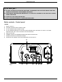
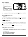
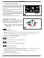
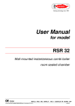
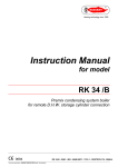
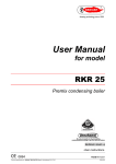
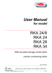
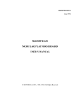
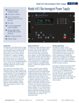
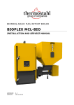
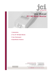
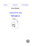
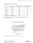
User Manual
for model
EKR 18
Premix condensing boiler
CE 0694
ENGLISH
USER INSTRUCTIONS
BOILER OPERATING INSTRUCTIONS
Make sure that the authorised technician who tested the boiler has stamped the guarantee booklet.
The installation, first start-up, regulation and maintenance operations must be carried out exclusively by
qualified personnel (e.g. THERMOSTAHL authorised Service Centres). Incorrect installation can cause
damage to property and injury to persons or animals, for which the manufacturer will not be held responsible.
During the installation, the technician must carry out the following checks:
■ The data on the data plate must correspond to that of the mains supply networks (gas, electricity, water).
■ The boiler must be regulated according to its designed use and performance.
■ The flue gas exhaust and combustion air intake system must be correctly installed and operational.
■ The exhaust gas discharge and ventilation systems must comply with the requirements of national and local
standards regardless of whether the boiler is installed indoors, outdoors or in its own cabinet (see section
“Reference standards”.
General warnings
If there is any doubt as to whether the appliance has been tested by an authorised technician, do not attempt
to start it. All maintenance and gas conversion operations MUST BE CARRIED OUT BY PROFESSIONALLY
QUALIFIED PERSONNEL, registered in accordance with current legislation.
Make sure that the requirements relating to the air intake and ventilation of the room in which the
boiler is to be installed have been complied with.
The boilers can be installed outdoors in a partially protected location, in accordance with current
standards and where the minimum external temperature does not fall below –10°C. The manufacturer
will not be held responsible for installation in locations where the temperature falls to below –10°C.
The boiler is fitted with an antifreeze system. If the boiler is installed in a location where there is a risk of
freezing, the anti-freeze system will only come into operation if the power is on and the gas supply valve is
open (the frost protection is active even with the ON/OFF switch in OFF position). The manufacturer will not
be held responsible for damage to the boiler caused by non-compliance with this instruction.
Should any part of the boiler freeze-up, do not attempt to light it under any circumstances, but instead call the
Service Centre immediately.
The appliance’s combustion system must be checked every two years. This check includes testing the
efficiency of the boiler and must be carried out by authorised personnel possessing the qualifications as
required by current law.
Do not obstruct the ventilation openings in rooms where there are gas-burning appliances installed (boiler,
cooker, etc.).
1
USER INSTRUCTIONS
If you smell gas …
DO NOT ACTIVATE ANY ELECTRIC SWITCHES, TELEPHONES OR ANY OTHER DEVICE THAT MAY
GENERATE ELECTRICAL DISCHARGES OR SPARKS.
OPEN DOORS AND WINDOWS IMMEDIATELY TO CREATE A CURRENT OF AIR THAT WILL RAPIDLY
CLEAR THE ROOM.
CLOSE ALL GAS TAPS AND VALVES.
CALL FOR PROFESSIONALLY QUALIFIED PERSONNEL.
Boiler controls - Control panel
LEGEND
1.
ON/OFF SWITCH
2. HEATING TEMPERATURE CONTROL KNOB
3.
D.H.W TEMPERATURE CONTROL KNOB.
4.
D.H.W TEMPERATURE DISPLAY BUTTON. (KEEP PRESSED FOR 5 SECONDS TO DISPLAY OUTSIDE
TEMPERATURE -ONLY WITH OPTIONAL OUTDOOR SENSOR)
5.
SERVICE BUTTON.
6.
SUMMER, WINTER OR SUMMER/WINTER MODE SELECTION BUTTON.
7.
TERMINAL BOARD FOR EXTERNAL WIRING.
8.
TEMPERATURE, ERROR CODE AND OPERATING STATUS DISPLAY.
8
Fig. 1
1
2
3
2
4 5 6
7
USER INSTRUCTIONS
Starting - up the boiler
•
Open the gas Isolation valve located under
the boiler.
•
Switch on the boiler by placing the ON/OFF
switch (1) in the ON position (see “Control
panel”).
•
The boiler will light automatically (with the
WINTER mode selected and room thermostat
connected).
•
Check that there are no flashing numbers on
the display 8 (see error codes). If code H2O
appears on the display 8 this denotes that
there is no water in the boiler. Consequently,
fill the system as described in section “Filling
the system”.
8
Fig. 1
1
2
3
4 5 6
7
■ “SUMMER” mode
To switch boiler operation to “SUMMER” mode, press button 6 (see fig. 1). The boiler will only work for the D.H.W
system. The “SUMMER” mode setting of the boiler is signalled by the symbol
panel.
lit continuously on the control
The automatic ignition system will light the burner every time there is a demand for domestic hot water. In this
case, the symbol
on the control panel will flash.
■ “WINTER” mode
To switch boiler operation to “WINTER” mode, press button 6 (see fig. 1). The boiler will only work for the central
heating system. The “WINTER” mode setting of the boiler is signalled by the symbol
control panel.
lit continuously on the
The automatic ignition system will light the burner every time there is a demand for room heating. In this case, the
symbol
on the control panel will flash.
■ “SUMMER-WINTER” mode
To switch boiler operation to “SUMMER/WINTER” mode, press button 6 (see fig. 1). The boiler will work for both
central heating/D.H.W systems. The “SUMMER/WINTER” mode setting of the boiler is signalled by the symbols
lit continuously on the control panel.
The automatic ignition system will light the burner every time there is a demand for room heating or domestic hot
water, the functioning is signalled by the symbols
flashing continuously on the control panel.
■ Regulating the heating temperature
The heating temperature is regulated by knob 2 (see fig.1).
•
Rotating the knob anticlockwise reduces the temperature.
•
Rotating the knob clockwise increases the temperature.
•
The range of temperature settings for the central heating runs from a minimum of 30°C to a maximum of
80°C, or, in the case of low temperature operation, from a minimum of 25°C to a maximum of 59°C.
■ D.H.W temperature control
The domestic hot water temperature is regulated by knob 3 (see “Control panel”).
•
Rotating the knob anticlockwise reduces the temperature.
•
Rotating the knob clockwise increases the temperature.
•
The range of temperature settings for the domestic hot water runs from a minimum of 35°C to a maximum of
60°C.
3
USER INSTRUCTIONS
■
Topping-up the system with water
The water pressure in the central heating circuit must be
checked during the entire period of operation of the boiler.
In this respect, the reading on the pressure gauge M (fig.
2), located on the lower part of the boiler, must not be less
than 1 bar.
If there is insufficient water in the boiler, the code H2O will
flash on the display (see fig 2).
To bring the system back up to pressure, open the
external filling tap R (fig. 2) and use the pressure gauge M
(fig. 2) to check that the systems pressure reaches the
middle of the green area (equal to 1,2 bar, see fig. 3) and
that the code H2O lights up.
R
M
2
When the operation is complete, close the fill tap.
Diagnostics – Error codes:
GREEN AREA
This paragraph contains a list of error codes that the boiler
may generate on the display 8 (see “Control panel”)
together with the relative indications and the operations
that the user can carry out to reset the boiler.
1.5 bar
1.2 bar
3 bar
0.5 bar
If the problem re-occurs after the following
actions have been taken, call an authorised
Service Centre.
3
_E01
E01_
E01 Ionisation block
Code E01 lit continuously on the display.
Check that the gas valve on the boiler and gas meter are open and that there is gas in the mains supply (or in
the tank).
Switch off then switch on the appliance using switch 1 (see “Control panel”) on the control panel.
When the error code on the display disappears, the boiler will restart.
If the problem persists, Call the Service Centre.
_E02
E02_
E02 Safety Thermostat tripped
Code E02 lit continuously on the display. Call the Service Centre.
_E03
E03_
E03 Flue Gas Thermostat tripped
Code E03 lit continuously on the display. Call the Service Centre.
_h2o
h2o_
h2o Water Pressure Switch tripped
Code H2O lit continuously on the display.
Check the water pressure in the central heating circuit. The reading on the pressure gauge M (see fig. 3),
located on the lower part of the boiler, must not be less than 1 bar .
If the pressure is less than 1 bar, top-up the system as described in paragraph “Filling the system”.
The boiler will restart automatically.
If the problem persists, Call the Service Centre.
4
USER INSTRUCTIONS
_E05
E05_
E05 Heating Sensor malfunction
Code E05 lit continuously on the display. Call the Service Centre.
_E06
E06_
E06 D.H.W Sensor malfunction
Code E06 lit continuously on the display. Call the Service Centre.
_E
E16_ Electric Fan Malfunction
Code E16 lit continuously on the display. Call the Service Centre.
_E22
E22_
E22 Parameter programming request
Code E22 lit continuously on the display. Call the Service Centre.
N.B. If the boiler is to be left unused for a long period of time, the user must do one of the following:
Make the boiler safe by disconnecting all the power supplies (electricity and gas), and draining the heating
system and the condensate trap.
Leave the boiler in standby, leaving the electricity and gas supplies connected and, consequently the anti-freeze
function.
5
THE TECHNICAL DATA AND MEASUREMENTS ARE PROVIDED FOR INFORMATION
PURPOSES ONLY AND ARE NOT BINDING. THE COMPANY RESERVES THE RIGHT
TO APPLY VARIATIONS WITHOUT PRIOR NOTIFICATION. NEITHER WILL THE
COMPANY BE HELD RESPONSIBLE FOR ANY INACCURACIES IN THIS HANDBOOK
DERIVING FROM PRINTING OR TRANSLATION ERRORS. E+OEALL RIGHTS
RESERVED. NO PART OF THIS DOCUMENT MAY BE REPRODUCED, MEMORISED
IN ANY FILING SYSTEMS OR TRANSMITTED IN ANY FORM WHATSOEVER,
INCLUDING ELECTRONIC, MECHANICAL, PHOTOCOPIES, RECORDINGS OR ANY
OTHER MEANS WITHOUT THE COMPANY’S PRIOR WRITTEN APPROVAL.