1
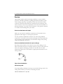
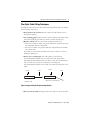
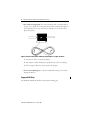
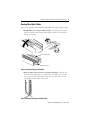
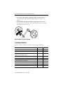
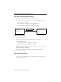
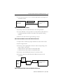
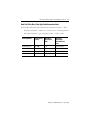
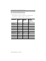
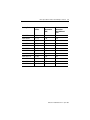
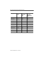
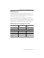
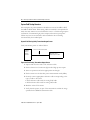
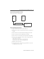
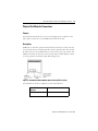
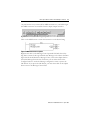
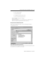
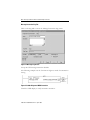
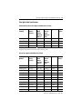
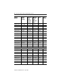
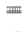
Fiber Optic Cable Installation and Handling
Instructions
Introduction
Fiber optic cables can be easily damaged if they are improperly handled or
installed. It is imperative that certain procedures be followed in the handling
of these cables to avoid damage and/or limiting their usefulness. The
information contained in this manual should serve as a guide to proper
handling, installing, testing, and for troubleshooting problems with fiber
optic cables.
For:
See page:
Overview
2
Fiber Optic Cable Pulling Techniques
3
Routing Fiber Optic Cables
5
Installation Checklist
6
Cleaning Techniques for Fiber Optic Cables
7
Fiber Optic Cable Attenuation Measurements
8
Plastic Fiber Optic Cable Attenuation Limits
12
SERCOS Attenuation Limits
15
System Field Testing Overview
16
Configuring Light Source
18
Physical Test Mode for Connections
19
Fiber Optic Cable Specifications
25
Rockwell Automation Support
BackCover
Publication 2090-IN010C-EN-P – April 2005
2
Fiber Optic Cable Installation and Handling Instructions
Overview
Optical fibers require special care during installation to ensure reliable
operation. Installation guidelines regarding minimum bend radius, tensile
loads, twisting, squeezing, or pinching of cable must be followed. Cable
connectors should be protected from contamination and scratching at all
times. Violation of any of these parameters causes increased attenuation or
permanent damage to the cable. The following are a few general comments
to consider when installing fiber optic cables.
Do not exceed maximum cable lengths
Make sure you check the installation instructions of the module for the
appropriate cable lengths to ensure proper operation.
You may experience additional attenuation loss when using bulkhead
connectors to join cables even when the total length is less than maximum.
Care should be used in maintaining total attenuation budget when joining
cables with bulkhead connectors.
Do not exceed minimum bend radius for a given cable type
Exceeding the bend radius of the cable can cause unseen damage to the
fibers of the cables that may not manifest itself for a period of time. This can
lead to an expensive restringing of cables at a later date. See the cable
specification tables later in this manual for appropriate bend radii for each
catalog number.
Bend
Radius
Figure 1 Correct Bend Radius
Avoid twisting cable
Use proper pulling techniques in laying out your cable. Putting twists in the
cable greatly increases your chances of breaking the fibers.
Publication 2090-IN010C-EN-P – April 2005
Fiber Optic Cable Installation and Handling Instructions
3
Fiber Optic Cable Pulling Techniques
Installation methods for both wire cables and optical fiber cables are similar.
Just remember these rules:
• Never pull on the connector. The connector/cable interface is not
designed for pulling.
• Use a pulling grip designed for pre-connected fiber optic cables. Grips
with a fixed pull ring should use a swivel to attach the pull rope.
• Monitor tension. Do not exceed the maximum tensile load.
– On runs from 40m to 100m, use proper lubricants and make sure they
are compatible with the cable jacket.
– On runs over 100m, use proper lubricants and pull from the middle
out to both ends.
If possible, use an automated puller with tension control or at least a
breakaway-pulling eye.
• Always use a straight pull. Use cable guides to maintain the
recommended bend radius. Do not exceed the cable bend radius.
Exceeding the bend radius harms the fibers. It may not be immediate, it
may even take a few years but eventually by exceeding the
recommended bend radius of the cable you reduce the useful life of the
cable.
Conduit
Straight Pull is OK.
Cable
Conduit
Cable
Offset Pull is not Recommended
Figure 2 Proper Pulling Technique Through Conduit
• Do not twist the cable. Putting a twist in the cable can stress the fibers.
Publication 2090-IN010C-EN-P – April 2005
4
Fiber Optic Cable Installation and Handling Instructions
• For a 40m or longer pull. If you are installing cable of lengths 40m or
longer, use a “figure 8" on the ground to prevent twisting. The figure 8
puts a half twist in on one side of the 8 and takes it out on the other,
preventing twists.
Figure 3 Prevent Twisting the Cable By Laying Cable in a Figure 8 Pattern
1. Lay cable on floor in a figure 8 pattern.
2. Turn Figure 8 cable 360 degrees (upside down) before continuing.
3. Pull in opposite direction (may require two people).
• Use a swivel-pulling eye, to prevent additional twisting of the cable
during installation.
Suggested Pull Grips
The Hubbell OPTISOK, Kellems Fiber-Optic Pulling grip
Publication 2090-IN010C-EN-P – April 2005
Fiber Optic Cable Installation and Handling Instructions
5
Routing Fiber Optic Cables
Take care to properly route cables through cabinets and right angle raceways.
• Install cables in raceways without loops. Avoid placing fiber optic
cables in raceways and conduits with copper cables to avoid excessive
loading or twisting.
Fiber Optic Cables
Power Cables
Figure 4 Using Raceways and Conduits
• Protect cables from excessive or frequent bending. Cables do not
have a flex rating. Routing on a cabinet door should be used as a last
resort. Special care must be taken to protect the cable and to avoid
exceeding the bend radius of the cable.
Figure 5 Routing Technique for Cabinet Door
Publication 2090-IN010C-EN-P – April 2005
6
Fiber Optic Cable Installation and Handling Instructions
• Use proper cable pulling techniques when routing cables. See
the section Fiber Optic Cable Pulling Techniques earlier in this
manual.
• Attach cables with plastic clamps having large surface areas.
Avoid pinching or squeezing cable. Cable clamps should be installed
manually with gentle pressure.
Figure 6 Proper Use of Plastic Clamps
Installation Checklist
Use the following installation checklist to ensure proper handling.
Installation Procedure
Maximum cable length not exceeded
Bending radius not exceeded
Maximum tensile load not exceeded;
proper pulling techniques used
Cable not squeezed or bent
Cable installed without loops in raceways
Cable protected from sharp edges
Fiber cable installed in separate raceways from copper
Cable connector cleanliness maintained
Cable connector finger tight to transceivers
Publication 2090-IN010C-EN-P – April 2005
Complete
Comments
Fiber Optic Cable Installation and Handling Instructions
7
Cleaning Techniques for Fiber Optic Cables
Proper cleaning of the fiber optic cable ends and transceivers is essential to
minimize system attenuation. Dirty fiber optic cables cross contaminate
their mating transceivers. Conversely a dirty transceiver contaminates its
mating fiber optic cable.
There are a variety of ways to clean fiber optic components. Readily available
prepackaged wipes, swabs and, canned air are suitable. Always choose an
optical grade cleaner for these purposes.
Cleaning Fiber Optic Cable Ends
Use a wet wipe to loosen particles on the end of the cable connector using a
circular or straight wiping motion while using care to avoid wiping over area
of pad that has already been used. Do not use a back and forth scrubbing
action. Always use a clean area of the swab for each connector. When in
doubt use a fresh wipe. Follow up the wet wipe cleaning with a dry wipe to
remove any residue. Use canned air to remove any lint from the cable end.
Cleaning Fiber Optic Transceivers
Choose an optical grade lint free swab that fits easily into the transceiver
barrel. Under some conditions a fast evaporating optical cleaning solvent
may be used to saturate the swab (e.g., 99% pure alcohol). The swab should
be gently placed into the barrel of the connector and rotate no more than
one turn. DO NOT rotate back-and-forth or round-and-round because this
could grind debris into the transceiver. The swabs should only be used
ONCE. Use a dry clean swab and insert into barrel and rotate once. Discard
swab. Use canned air to blow out the barrel.
Chemtronics and Coventry are just some of the manufacturers of suitable
cleaning swabs and wipes.
• Newark Electronics:
92N4770 Fiber Clean Dispense System (cleaning cloth/tape)
• Contact East supplies:
Optic Wipes part # 127-734
Fiber Optic Swabs part # 416-761
Publication 2090-IN010C-EN-P – April 2005
8
Fiber Optic Cable Installation and Handling Instructions
Fiber Optic Cable Attenuation Measurements
1. Inspect and clean the ends of the reference cable.
2. Securely connect appropriate reference cable corresponding to the
type of cable to be tested.
• POF reference cable used for testing POF cable
• HCS reference cable used for testing HCS cable
1 meter reference
LED Light Source
650nM nominal
Optometer Set to 0dB
reference
Figure 7 Zero dB Reference
3. Turn on light Source
4. Turn on optometer and select appropriate wavelength.
5. Verify Output Power
a. POF reference cable -7.5dBM to -3.5dBM
b. HCS reference cable -18dBM to -10dBM
Note: If output power is out of range, verify that the source has fresh
batteries and proper calibration.
6. Set the zero db reference for the optometer. (see optometer
reference manual)
Cable Attenuation Measurement
1. Inspect ends of cable for proper termination. Clean ends of fiber.
2. Turn on light Source
Publication 2090-IN010C-EN-P – April 2005
Fiber Optic Cable Installation and Handling Instructions
9
3. Verify that optometer is set to measure appropriate wavelength and
attenuation in dB.
Test Cable
Optometer measuring
loss in dB
LED Light Source
650nM nominal
Figure 8 Attenuation Measurement
4. Securely connect test cable between source and optometer.
5. Use the dB value on the optometer to verify that the cable under test
is within specification listed in the table for that specific catalog
number.
6. Reverse the cable and test again starting at step 2.
Cable Attenuation Measurement with Bulkhead Connector
1. Inspect ends of cable for proper termination. Clean ends of fiber.
2. Turn on light Source
3. Securely connect appropriate reference cable corresponding to the
type of cable to be tested.
• POF reference cable used for testing POF cable
• HCS reference cable used for testing HCS cable
4. Securely connect bulkhead connector to reference cable.
5. Securely connect test cable between bulkhead connector and
optometer.
LED Light
Source
650nM
nominal
1 meter
reference
cable
Coupler
2090-s-blhd
Test Cable
Optometer measuring
loss in dB
Figure 9 Attenuation Measurement with Bulkhead Connector
Publication 2090-IN010C-EN-P – April 2005
10
Fiber Optic Cable Installation and Handling Instructions
6. Verify that optometer is set to measure appropriate wavelength and
attenuation in dB.
7. Use the dB value on the optometer to verify that the cable under test
is within specification listed in the table for that specific catalog
number.
8. Reverse the cable and test again starting at step 2.
Recommended Equipment List
650 nm LED Light Source - Tempo 253B
Optometer - Tempo CP-3137
Mating adapters for SMA connectors - Tempo 905-120-5000
• 1m HCS Reference Cable with recorded attenuation - XSOPTZCS
T01SSFSF0001MZ
• 1m POF Reference Cable - Tempo PO1XSFS0001M1
Publication 2090-IN010C-EN-P – April 2005
Fiber Optic Cable Installation and Handling Instructions
11
Hard Clad Silica Glass Fiber Optic Cable Attenuation Limits
Hard Clad Silica Glass (HCS) Fiber cable attenuation calculations for cables <= 100m
HCS Cable Attenuation = Cable Loss + Connector Loss + Finishing Tolerance
HCS Cable Attenuation = ((15 - 4*log(Lkm))* Lkm) + 1.5dB + 0.5dB
Catalog Number
Length meters,
(inches)
Maximum
Attenuation
(dB)
Maximum
Attenuation
With Bulkhead
Conn.
2090-SCVG50-0
50, (1968)
3.01
NOT ALLOWED
2090-SCVG100-0
100, (3936)
3.90
NOT ALLOWED
2090-SCVG150-0
150, (5904)
3.90
NOT ALLOWED
2090-SCVG200-0
200, (7872)
3.90
NOT ALLOWED
Publication 2090-IN010C-EN-P – April 2005
12
Fiber Optic Cable Installation and Handling Instructions
Plastic Fiber Optic Cable Attenuation Limits
Plastic Fiber (POF) Attenuation Calculations:
POF Attenuation = Cable Loss + Connector Loss + Finishing Tolerance
POF Attenuation = (0.19dB/m * Length) + 1.5dB + 0.5dB
Catalog Number
Length meters,
(inches)
Maximum
Attenuation
(dB)
Maximum
Attenuation
With Bulkhead
Conn.
2090-SCEP0-1
0.1, (4)
2.02
5.02
2090-SCEP0-2
0.2, (7)
2.04
5.04
2090-SCEP0-3
0.3, (12)
2.06
5.06
2090-SCEP1-0
1, (39)
2.19
5.19
2090-SCEP3-0
3, (118)
2.57
5.57
2090-SCEP5-0
5, (197)
2.95
5.95
2090-SCEP8-0
8, (315)
3.52
6.52
2090-SCEP10-0
10, (394)
3.90
6.90
2090-SCEP15-0
15, (591)
4.85
7.85
2090-SCEP20-0
20, (787)
5.80
8.80
2090-SCEP25-0
25, (984)
6.75
9.75
2090-SCEP32-0
32, (1260)
8.08
11.08
Publication 2090-IN010C-EN-P – April 2005
Fiber Optic Cable Installation and Handling Instructions
Catalog Number
Length meters,
(inches)
Maximum
Attenuation
(dB)
Maximum
Attenuation
With Bulkhead
Conn.
2090-SCNP0-1
0.1, (4)
2.02
5.02
2090-SCNP0-3
0.3, (12)
2.06
5.06
2090-SCNP0-9
0.9, (35)
2.17
5.17
2090-SCNP1-0
1, (39)
2.19
5.19
2090-SCNP3-0
3, (118)
2.57
5.57
2090-SCNP5-0
5, (197)
2.95
5.95
2090-SCNP8-0
8, (315)
3.52
6.52
2090-SCNP10-0
10, (394)
3.90
6.90
2090-SCNP15-0
15, (591)
4.85
7.85
2090-SCNP20-0
20, (787)
5.80
8.80
2090-SCNP25-0
25, (984)
6.75
9.75
2090-SCNP32-0
32, (1260)
8.08
11.08
13
Publication 2090-IN010C-EN-P – April 2005
14
Fiber Optic Cable Installation and Handling Instructions
Catalog Number
Length meters,
(inches)
Maximum
Attenuation
(dB)
Maximum
Attenuation
With Bulkhead
Conn.
2090-SCVP0-1
0.1, (4)
2.02
5.02
2090-SCVP0-3
0.3, (12)
2.06
5.06
2090-SCVP0-9
0.9, (35)
2.17
5.17
2090-SCVP1-0
1, (39)
2.19
5.19
2090-SCVP3-0
3, (118)
2.57
5.57
2090-SCVP5-0
5, (197)
2.95
5.95
2090-SCVP8-0
8, (315)
3.52
6.52
2090-SCVP10-0
10, (394)
3.90
6.90
2090-SCVP15-0
15, (591)
4.85
7.85
2090-SCVP20-0
20, (787)
5.80
8.80
2090-SCVP25-0
25, (984)
6.75
9.75
2090-SCVP32-0
32, (1260)
8.08
11.08
Publication 2090-IN010C-EN-P – April 2005
Fiber Optic Cable Installation and Handling Instructions
15
SERCOS Attenuation Limits
The SERCOS standard defines different allowable attenuation losses for
both Plastic and Hard Clad Silica fiber optic cables. The differences for the
two types of fiber are due to the drive characteristics of the transmitters into
the different diameters of POF and HCS cables.
The fiber optic transmitter power is measured using a 1-meter length
reference standard cable to an optometer. SERCOS has system attenuation
limits, which are governed by the minimum light power required for proper
operation of the receiver. SERCOS generally includes a bulkhead connector
in the transmitter to receiver path. The table below shows these limits.
SERCOS System Optical Transmission line Specifications @ 650nM
Continuous Light ON
Plastic Optical Fiber
(POF)
Glass Optical Fiber
(HCS)
Transmitter Min Power
-7.5 dBm (uW)
-18 dBm (uW)
Transmitter Max Power
-3.5 dBm (uW)
-10 dBm (uW)
Receiver Min Power
-20 dBm (uW)
-22 dBm (uW)
Receiver Max Power
-5.0 dBm (uW)
-7.0 dBm (uW)
System Attenuation limit
POF Cable >= 29.6 m
HCS Cable >= 200 m
Max point to point
attenuation
12.5 dB
4.0 dB
Publication 2090-IN010C-EN-P – April 2005
16
Fiber Optic Cable Installation and Handling Instructions
System Field Testing Overview
The total point to point attenuation should never exceed 12.5dB for POF
and 4dB for HCS cables. Field testing cables as installed is accomplished in
much the same manner as tests described in section 1. Field-testing requires
verification of transmitter light power output and receiver input power.
Cables may have more attenuation after installation due to bending
encountered by the installed path.
System Field Testing Verify Transmitter Output Power
Verify transmitter power as outlined below:
SERCOS
Drive or
Module
Transmit
1 meter in length reference cable
Optometer Set to
measure power in dBm
Figure 10 Field Testing Transmitter Output Power
1. Inspect and clean the ends of the reference cable.
2. Put the Source into Continuous light mode. High power output.
3. Turn on optometer and select appropriate wavelength.
4. Put the meter into the absolute power measurement mode(-dBm)
5. Securely connect appropriate reference cable corresponding to the
type of cable to be tested.
• POF reference cable used for testing POF cable
• HCS reference cable used for testing HCS cable
6. Read the value off the meter.
7. Verify that the power out put of the transmitter is within the range
specified in the SERCOS attenuation table.
Publication 2090-IN010C-EN-P – April 2005
Fiber Optic Cable Installation and Handling Instructions
17
System Field Testing Verify Receiver Power
Verify receiver power as outlined below:
SERCOS
Drive or
Module
Receiver
SERCOS
Drive or
Module
Transmit
Cable under Test as installed
Optometer Set to measure
power in dBm
Figure 11 Field Testing Receiver Power
1. Inspect and clean the ends of the cable under test.
2. Disconnect the cable to be tested from the receiver of the Drive or
module.
3. Put the Source into Continuous light mode. High power output.
4. Turn on optometer and select appropriate wavelength.
5. Put the meter into the absolute power measurement mode(-dBm)
6. Securely connect appropriate reference cable corresponding to the
type of cable to be tested.
• POF reference cable used for testing POF cable
• HCS reference cable used for testing HCS cable
7. Read the value off the meter.
8. Verify that the power is within the range specified for a receiver in
the SERCOS attenuation table.
Publication 2090-IN010C-EN-P – April 2005
18
Fiber Optic Cable Installation and Handling Instructions
Configuring Light Source
Configure test module as test light source
1. Plug module into ControlLogix rack
2. Set desired light power. Switch up for hi power output. Switch down
for low power output.
Configure Ultra3000TM drive as test light source
1. Set baudrate rotary switch to the 9:00 position to enable continuous
light output mode.
2. Power up the drive
The drive is outputting in continuous light mode at maximum output power.
Configure KinetixTM family drive as test light source
1. Set DIP switch 1 to proper position to enable high power output.
(See drive user manual for proper position).
2. Connect a computer to the Drive via a serial port and anaconda.
3. Use drive explorer software to set IDN701 to a value of 91 to enable
continuous light output mode.
The drive remains in this mode until power is cycled.
Measurement using general purpose LED source.
Publication 2090-IN010C-EN-P – April 2005
Fiber Optic Cable Installation and Handling Instructions
19
Physical Test Mode for Connections
Purpose
The Physical Test Mode lets you to test and diagnose the condition of the
fiber optical connections to the SERCOS interface™ module.
Description
SERCOS is a real-time optical serial interface between the control unit and
its associated drives to transmit periodic and non-periodic data. The module
provides three tri-color LED indicators to show the state of the system. The
LEDs are located on the bezel of the module. These LEDs display a variety
of orange patterns for Physical Test Mode diagnostics.
Figure 12 1756-MxxSE Motion Module Bezel Showing LED Locations
The table below offers an explanation of the OK indicator.
If the OK indicator
displays:
The module status is:
Flashing orange light
Physical Test Mode is active.
Publication 2090-IN010C-EN-P – April 2005
20
Fiber Optic Cable Installation and Handling Instructions
The table below offers an explanation of the SERCOS ring indicator.
If the SERCOS ring
indicator displays:
The module status is:
Solid orange light
Continuous light is active.
Flashing orange light
Zero bit stream is active.
The table below offers an explanation of the CP indicator.
If the CP indicator
displays:
The module status is:
Flashing fast orange light
Hi power is active.
Flashing slow orange light
Low power is active.
To facilitate testing of fiber optical connections, a test mode via CIP Generic
Message Type to the SERCOS Axis object can be configured. This test
mode lets you set hi and low optical power, continuous light and zero bit
stream test modes. This service closes all connections upon execution,
which shuts down motion. It is recommended that all motion be shut down
prior to executing this instruction. The SERCOS fiber transmit cable should
also be disconnected from the module in preparation for attachment of
optical test equipment.
ATTENTION
The Module Must be Reset/RIUP (Removed & Inserted Under Power) to
cancel the test function.
Publication 2090-IN010C-EN-P – April 2005
Fiber Optic Cable Installation and Handling Instructions
21
To perform the test you must add an MSG instruction to your ladder logic.
The MSG instruction is accessible from the Input/Output selection.
Figure 13 MSG Instruction from Input/Output Tab
Click on the MSG button to insert the instruction on the desired rung.
Figure 14 MSG Instruction Faceplate
Right mouse click on the Message Control operand field and select New
Tag. Enter a name for the tag and make sure Message is the value in the Data
Type field. It should default to Message. If not, click on the ellipsis button
and select Message from the list. From here you can either click on the
Configure button to reach the Message configuration screen or press the
OK button. If you press the OK button, you must then click on the ellipsis
button next to the Message Control field.
Publication 2090-IN010C-EN-P – April 2005
22
Fiber Optic Cable Installation and Handling Instructions
Message Instruction Settings
The Message Configuration Screen has three tabs: Configuration,
Communication and Tag. This is where you set the values for the test.
Figure 15 Message Configuration Tab
Enter the following values for the fields on the Configuration Tab screen.
Message Type: CIP generic
Service Type: Custom
Service Code: 51 hex.
Class: 315 hex.
Instance: 0
Attribute: 0.
Source Element: The Source Element must be an INT array of 1. The
first element of the array needs to be set to the value of the desired test
mode.
Servicecode[0] = Value set to desired Physical testmode
Publication 2090-IN010C-EN-P – April 2005
Fiber Optic Cable Installation and Handling Instructions
23
0 = Set Continuous Light
1 = Set Zero Bit Stream
2 = Set High transmission power level
3 = Set Low transmission power level
Source Length: must be set to 2 bytes.
Destination Field: The resp_string must be set to a INT array of 1.
There is no response specific data for this instruction.
Message Instruction Communications Tab
Click on the Communication Tab to access the Message Instruction
Communication screen.
Figure 16 Message Communication Screen
At this screen you set the path to the module. Use the browse button to find
the module then set the Path to the module.
Publication 2090-IN010C-EN-P – April 2005
24
Fiber Optic Cable Installation and Handling Instructions
Message Instruction Tag Tab
Click on the Tag Tab to access the Message Instruction Tag screen.
Figure 17 Message Tag Screen
Accept the CIP message instruction defaults.
The following example sets the Continuous Light test mode for attenuation
testing.
Figure 18 Ladder Diagram of MSG Instruction
Check the LED display to verify instruction execution.
Publication 2090-IN010C-EN-P – April 2005
Fiber Optic Cable Installation and Handling Instructions
25
Fiber Optic Cable Specifications
Hard Clad Silica Glass Fiber Optic Cable Mechanical Limits
Catalog
Number
Length
meters,
(inches)
Long Term
Bend
Radius
No Load
mm (in.)
Maximum Impact
Tensile
Load
Newtons
(Lbs.)
Twist
(times)
2090-SCVG50-0
50, (1970)
30 (1.2)
<98 (22)
490 N/5 cm
Avoid*
2090-SCVG100-0
100, (3937)
30 (1.2)
<98 (22)
490 N/5 cm
Avoid*
2090-SCVG150-0
150, (5905)
30 (1.2)
<98 (22)
490 N/5 cm
Avoid*
2090-SCVG200-0
200, (7874)
30 (1.2)
<98 (22)
490 N/5 cm
Avoid*
*Highly susceptible to fracture under twisting load.
Plastic Fiber Optic Cable Mechanical Limits
Catalog
Number
Length
meters,
(inches)
Long Term
Bend
Radius
No Load
mm (in.)
Maximum Impact
Tensile
Load
Newtons
(Lbs.)
Twist
(times)
2090-SCEP0-1
0.1, (4)
25.4 (1.0)
< 70 (15)
0.4 N·m
5
2090-SCEP0-3
0.3, (12)
25.4 (1.0)
< 70 (15)
0.4 N·m
5
2090-SCEP0-9
0.9, (35)
25.4 (1.0)
< 70 (15)
0.4 N·m
5
2090-SCEP1-0
1, (39)
25.4 (1.0)
< 70 (15)
0.4 N·m
5
2090-SCEP3-0
3, (118)
25.4 (1.0)
< 70 (15)
0.4 N·m
5
2090-SCEP5-0
5, (197)
25.4 (1.0)
< 70 (15)
0.4 N·m
5
2090-SCEP8-0
8, (315)
25.4 (1.0)
< 70 (15)
0.4 N·m
5
2090-SCEP10-0
10, (394)
25.4 (1.0)
< 70 (15)
0.4 N·m
5
2090-SCEP15-0
15, (591)
25.4 (1.0)
< 70 (15)
0.4 N·m
5
2090-SCEP20-0
20, (787)
25.4 (1.0)
< 70 (15)
0.4 N·m
5
2090-SCEP25-0
25, (984)
25.4 (1.0)
< 70 (15)
0.4 N·m
5
Publication 2090-IN010C-EN-P – April 2005
26
Fiber Optic Cable Installation and Handling Instructions
Catalog
Number
Length
meters,
(inches)
Long Term
Bend
Radius
No Load
mm (in.)
Maximum Impact
Tensile
Load
Newtons
(Lbs.)
Twist
(times)
2090-SCEP32-0
32, (1260)
25.4 (1.0)
< 70 (15)
0.4 N·m
5
2090-SCNP0-1
0.1, (4)
25.4 (1.0)
< 70 (15)
0.4 N·m
5
2090-SCNP0-3
0.3, (12)
25.4 (1.0)
< 70 (15)
0.4 N·m
5
2090-SCNP0-9
0.9, (35)
25.4 (1.0)
< 70 (15)
0.4 N·m
5
2090-SCNP1-0
1, (39)
25.4 (1.0)
< 70 (15)
0.4 N·m
5
2090-SCNP3-0
3, (118)
25.4 (1.0)
< 70 (15)
0.4 N·m
5
2090-SCNP5-0
5, (197)
25.4 (1.0)
< 70 (15)
0.4 N·m
5
2090-SCNP8-0
8, (315)
25.4 (1.0)
< 70 (15)
0.4 N·m
5
2090-SCNP10-0
10, (394)
25.4 (1.0)
< 70 (15)
0.4 N·m
5
2090-SCNP15-0
15, (591)
25.4 (1.0)
< 70 (15)
0.4 N·m
5
2090-SCNP20-0
20, (787)
25.4 (1.0)
< 70 (15)
0.4 N·m
5
2090-SCNP25-0
25, (984)
25.4 (1.0)
< 70 (15)
0.4 N·m
5
2090-SCNP32-0
32, (1260)
25.4 (1.0)
< 70 (15)
0.4 N·m
5
2090-SCVP0-1
0.1, (4)
40.0 (1.6)
< 245 (55)
0.4 N·m
5
2090-SCVP0-3
0.3, (12)
40.0 (1.6)
< 245 (55)
0.4 N·m
5
2090-SCVP0-9
0.9, (35)
40.0 (1.6)
< 245 (55)
0.4 N·m
5
2090-SCVP1-0
1, (39)
40.0 (1.6)
< 245 (55)
0.4 N·m
5
2090-SCVP3-0
3, (118)
40.0 (1.6)
< 245 (55)
0.4 N·m
5
2090-SCVP5-0
5, (197)
40.0 (1.6)
< 245 (55)
0.4 N·m
5
2090-SCVP8-0
8, (315)
40.0 (1.6)
< 245 (55)
0.4 N·m
5
2090-SCVP10-0
10, (394)
40.0 (1.6)
< 245 (55)
0.4 N·m
5
2090-SCVP15-0
15, (591)
40.0 (1.6)
< 245 (55)
0.4 N·m
5
Publication 2090-IN010C-EN-P – April 2005
Fiber Optic Cable Installation and Handling Instructions
27
Catalog
Number
Length
meters,
(inches)
Long Term
Bend
Radius
No Load
mm (in.)
Maximum Impact
Tensile
Load
Newtons
(Lbs.)
Twist
(times)
2090-SCVP20-0
20, (787)
40.0 (1.6)
< 245 (55)
0.4 N·m
5
2090-SCVP25-0
25, (984)
40.0 (1.6)
< 245 (55)
0.4 N·m
5
2090-SCVP32-0
32, (1260)
40.0 (1.6)
< 245 (55)
0.4 N·m
5
Publication 2090-IN010C-EN-P – April 2005
Rockwell Automation Support
Rockwell Automation provides technical information on the web to assist
you in using our products. At http://support.rockwellautomation.com, you
can find technical manuals, a knowledge base of FAQs, technical and
application notes, sample code and links to software service packs, and a
MySupport feature that you can customize to make the best use of these
tools.
For an additional level of technical phone support for installation,
configuration and troubleshooting, we offer TechConnect Support
programs. For more information, contact your local distributor or Rockwell
Automation representative, or visit http://support.rockwellautomation.com.
Installation Assistance
If you experience a problem with a hardware module within the first 24
hours of installation, please review the information that's contained in this
manual. You can also contact a special Customer Support number for initial
help in getting your module up and running:
United States
1.440.646.3223
Monday – Friday, 8am – 5pm EST
Outside United
States
Please contact your local Rockwell Automation representative for
any technical support issues.
On-Line Documentation
Documentation for Rockwell Automation products can be downloaded free
of charge in pdf format from: http://literature.rockwellautomation.com
Ultra3000 and Kinetix are trademarks of Rockwell Automation.
www.rockwellautomation.com
Corporate Headquarters
Rockwell Automation, 777 East Wisconsin Avenue, Suite 1400, Milwaukee, WI, 53202-5302 USA, Tel: (1) 414.212.5200, Fax: (1) 414.212.5201
Headquarters for Allen-Bradley Products, Rockwell Software Products and Global Manufacturing Solutions
Americas: Rockwell Automation, 1201 South Second Street, Milwaukee, WI 53204-2496 USA, Tel: (1) 414.382.2000, Fax: (1) 414.382.4444
Europe: Rockwell Automation SA/NV, Vorstlaan/Boulevard du Souverain 36-BP 3A/B, 1170 Brussels, Belgium, Tel: (32) 2 663 0600, Fax: (32) 2 663 0640
Asia Pacific: Rockwell Automation, 27/F Citicorp Centre, 18 Whitfield Road, Causeway Bay, Hong Kong, Tel: (852) 2887 4788, Fax: (852) 2508 1846
Headquarters for Dodge and Reliance Electric Products
Americas: Rockwell Automation, 6040 Ponders Court, Greenville, SC 29615-4617 USA, Tel: (1) 864.297.4800, Fax: (1) 864.281.2433
Europe: Rockwell Automation, Brühlstraße 22, D-74834 Elztal-Dallau, Germany, Tel: (49) 6261 9410, Fax: (49) 6261 1774
Asia Pacific: Rockwell Automation, 55 Newton Road, #11-01/02 Revenue House, Singapore 307987, Tel: (65) 351 6723, Fax: (65) 355 1733
Publication 2090-IN010C-EN-P – April 2005
Supersedes publication 2090-IN010A-EN-P – March 2004
PN 321174-P03
Copyright © 2004 Rockwell Automation, Inc. All rights reserved. Printed in the U.S.A.