1
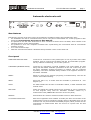
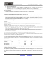
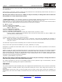
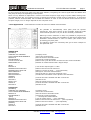
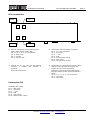
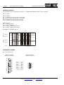
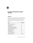
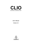
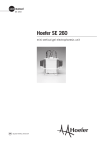
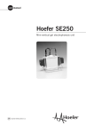
page 0
ET2-ST2 Electronic turntable
professional instruments
ET Commander 3.3
Automatic Electronic Turntable Program for
Win95/98
To start after installation please input your personal password
below.
Password
-
ET Commander XP
Outline ET2/ST2 Automatic Electronic
Turntable control software for Win 2000/XP
After installation the program do not ask any password.
Hardware & Software ET2 / ST2 - ET Commander 3.3 and
XP customer support email to: http\\[email protected]
outline s.n.c. di noselli g. & c. - v. leonardo da vinci, 56 - 25020 flero (bs) - italy - tel. +39-30-3581341 fax +39-30-3580431
Web Site: http://www.outline.it E-Mail : [email protected]
professional instruments
ET2-ST2 Electronic turntable
page 1
Automatic electronic unit
10
CO M PUTER
PA R A LL E L PO R T
T U R N TA B L E
(R E VE R S E S L AV E )
RES ET
AUTO
Z E R O
1 2.5
15
R
1 7.5
7 .5
5
M ANUAL
TTL O UTP UT
TIM E ADJ.
20
E
2 .5
E L E C T R O N IC ID S W IT C H
CO UN TER /CW
CLOCKW ISE
T
2
2 2.5
DEG STEP
CO UN TER /CW
CLOCKW ISE
A U T O M A T I C E L E C T R O N IC T U R N T A B L E
New features
Following the success of the first version of the Outline’s turntables, Outline has upgraded the units:
the turntables can now be controlled entirely via PC using the ET Commander 3.3 version program for Win
95/98 and ET Commander XP version for Win 2000/XP.
It's possible to use the same electronics to drive a second so-called “slave” turntable, which rotates in the
opposite direction to the main turntable.
It’s possible to drive two completes turntable sets synchronising the movements with ET Commander
software versions.
2.5° is the minimum step.
New ST2 mechanics has better robustness than precedent version in the same size.
Front panel
COMPUTER PARALLEL PORT:
connector for connection to the parallel port of a PC by means of the cable
supplied. Used to control the turntable with the ET Commander program.
For any software customizing, see “Control protocol”.
TURNTABLE (REVERSE SLAVE):
connector for connecting a second turntable. This must always be used
along with the Master turntable (connection on the rear of the unit), since
the Slave turntable’s forward movement or position can’t be controlled
separately. The Slave turntable always rotates in the opposite direction to
the Master turntable.
RESET:
button to reset at zero degrees (beginning of measurement). Can also be
used to avoid cables twisting.
ZERO:
when this LED is lit, it means that the turntable is positioned at
degrees (0°)
AUTO:
the LEDs indicate the direction of turntable rotation, in both automatic and
manual mode.
DEG STEP:
switch for setting the angular steps from a minimum of 2.5 to a maximum
of 22.5 degrees. Only used for automatic turntable control by a
measurement card (COMPUTER connector on the rear panel).
MANUAL:
these buttons are used for manual turntable control in both directions.
TTL OUTPUT DELAY ADJ:
Semi-fixed regulation which enables to modify the time of execution of the
measurement cycles by introducing a delay which is adjustable from 3 to 25
seconds. Can only be used with the MLSSA program, which provides for the
continuation of measurement after the arrival of a pulse from the ET2
control unit.
outline s.n.c. di noselli g. & c. - v. leonardo da vinci, 56 - 25020 flero (bs) - italy - tel. +39-30-3581341 fax +39-30-3580431
Web Site: http://www.outline.it E-Mail : [email protected]
zero
page 2
ET2-ST2 Electronic turntable
professional instruments
Rear panel
VCC IN 12/20 V:
XLR connector for the power supply of the entire system with a DC power
supply of between 12 and 20 Volts. The LED alongside lights up when
current reaches this connector.
TURNTABLE:
connector for connecting the control unit to the MASTER turntable.
COMPUTER:
connector for connection to the measurement card (LMS, MLSSA, CLIO, TEF
or others for which manufacturer suggest to use ET2/ST2 Outline).
Interconnections
- ET Commander - the turntable is controlled directly by the PC through its parallel port. A connector cable is
supplied with a 25-pin connector (DB25) and a 9-pin connector (DB9). In the event of two turntables being
controlled by a single PC, a splitter must be requested.
- LMS Applications - the turntable is synchronized by means of the TTL pulse on the 15-pin connector (DB15)
of the LMS PC CARD (see Operation Manual LMS4 1-9). The cable necessary for this connection is supplied with
the turntable. An extension cable with 9-pin connectors (DB9) is also supplied, as this is indispensable for
completing the LMS PC CARD / CONTROL UNIT ET2 connection.
- MLSSA Applications – the turntable is synchronized by TTL pulses on the 9-pin connector of the MLSSA PC
CARD. The cable supplied (DB9) enables direct MLSSA CARD / ET2 CONTROL UNIT connection.
- CLIO System - the turntable is synchronized by means of a TTL pulse generated by the CLIO software
directly via the parallel port. A DB25 male connector must be soldered to the cable supplied (with the female
DB9 connector). As explained in the CLIO User’s Manual (Section 7.4.4), the Start signal (DB9 pin 2) must be
soldered to pin 9, and the ground (DB9 pin 4) to pin 22 (or one of the pins between 18 and 25). The extension
cable supplied (DB9 male connectors) must be attached to the cable’s female DB9.
- TEF System – the turntable is synchronized by means of TTL pulses via the "External Trigger" connector. A
Switchcraft #60PC4F connector must be soldered to the cable supplied (with the DB9 female connector). As
explained in the TEF20 User's Manual, the Start signal (DB9 pin 2) must be soldered to pin 2, the return signal
(DB9 pin 5) to pin 4, and the ground (DB9 pin 4) to pin 1. The extension cable supplied (DB9 male connectors)
must be connected to the cable’s female DB9.
The ET2 Electronic Control Unit and ST2 Turntable are interconnected using the 10-metre multicore cable
supplied.
Software
- ET Commander - a program, supplied in both version Win 95/98/ME and Win2000/XP, which enables to
control one or two Outline ET2-ST2 turntables via PC.
It’s now possible to control the ET2 electronics directly using the PC interface in order to have complete control
of the turntable.
Main features:
Back and forward movement to a preset position
Automatic 360° rotation with adjustable steps
Storage of a series di positions in a macro
The start of automatic 360° rotation steps and automatic macro rotation can be controlled in 4 ways:
outline s.n.c. di noselli g. & c. - v. leonardo da vinci, 56 - 25020 flero (bs) - italy - tel. +39-30-3581341 fax +39-30-3580431
Web Site: http://www.outline.it E-Mail : [email protected]
professional instruments
ET2-ST2 Electronic turntable
page 3
a) Manual: by pressing a key
b) Timer: automatically timed
c) External: by means of an external signal on the parallel port (e.g. by means of a pulse from a
measurement card. or by a command directly trough DLL supplied (version for Win2000/XP).
d) Internal: by means of the direct reading of the parallel port (advisable only for expert programmers).
With two turntables:
Possibility of automatic simultaneous 360° rotation in sequential or alternate mode.
- LMS Applications (Dos Version) – The software necessary for preparing four types of polar plots is
supplied with the OUTLINE ST2 turntable and relative ET2 control unit.
1. SPL Normal Fixed Frequency: the macro which carries out this measurement is POLFIX.MAC (for versions
previous to 3.5) or POLFIX35.MAC (for 3.5 and later versions), which uses the POL***.SET files to set the
measurement parameters and the POLFIX.LIB file to store the results. A special Menu enables to choose the
test frequency from 18 frequencies at intervals of 1/3 of an octave.
In this case, 24 measurements are taken with different angular positions; set the DEG STEP switch on the
ET2control unit at 15 degrees.
Example:
Operation : (M)acro
Explanation: enter the Menu Macro and use the cursor keys (Up/Down arrows) to choose the Macro to run.
Operation : (L)oad
Explanation: the Marco starts running; follow the indications in the Macro itself to continue.
2. SPL Gated Fixed Frequency: the macro which takes this measurement is POLFIXG.MAC (for versions released
before 3.5) or POLFIG35.MAC (for 3.5 and later versions), which uses the POL***.SET files to set
measurement parameters and the POLFIX.LIB file to store the results.
A special Menu enables to choose the test frequency from 18 frequencies at intervals of 1/3 of an octave.
In this case, 24 measurements are taken with different angular positions; set the DEG STEP switch on the
ET2 control unit at 15 degrees.
The results can be stored, recalled and layered following standard LMS program procedure.
NB: the preset frequency band is 20Hz – 20kHz. To change it, the SPLPOLG.SET and SPLPOL.SET files must be
reset with the new parameters using LMS’s Quick Set-up.
Only for those using versions of LMS released previously to 3.5 To ensure perfect sync between program execution and turntable movement, some system parameters (SCP)
must be changed: this can be easily done in the LMS program itself. The changes to be made can be summed
up as follows:
Type of measurement
Standard
SPL Nor Fix
SPL Gat Fix
SPL Nor Sweep
SPL Gat Sweep
SCP15
Yes
No
No
-
Beep
Beep
-
SCP19
SCP20 SCP41
100
2000
2000
2000
2000
400
20000
20000
400
400
In particular, the SCP41 parameter in fixed frequency measurements must be >= 20000 to introduce an
additional delay between measurements and enable the turntable to be rotated in the most unfavourable
conditions (steps of 22.5 degrees).
The change to the SCP20 parameter is indispensable to set the correct length of the TTL control pulse and
ensure perfect compatibility between the ET2 electronic controller and the LMS program.
The change to parameters SCP15 and SCP19 isn’t indispensable, but advisable to enable the plots to be drawn
faster.
outline s.n.c. di noselli g. & c. - v. leonardo da vinci, 56 - 25020 flero (bs) - italy - tel. +39-30-3581341 fax +39-30-3580431
Web Site: http://www.outline.it E-Mail : [email protected]
page 4
ET2-ST2 Electronic turntable
professional instruments
This operation must be carried out before running the necessary Macro and anyway is prompted at the start of
the actual Macro.
With version 3.5 and later releases of LMS, the SCP parameters are automatically defined within the Macro, so
the abovementioned procedure is not necessary.
NB: the preset value for Osc Level is -20dBm. It may be necessary to change this value to make the
best possible use of the measurement system.
- MLSSA Applications – The software necessary for setting angular dispersion with different increments of
angular position is supplied with the OUTLINE ST2 turntable and relative ET2 control unit.
Preset steps are 5, 10 and 15 degrees for an overall rotation of 180 degrees. The choice of the various modes is
made by running the POLMAIN Macro and following the instructions it contains.
Es. (M)acro (L)oad
message: MACRO LOAD FILENAME
reply: key in POLMAIN (or Right Arrow) <enter>
(M)acro (E)xecute
message: MACRO LOAD FILENAME
reply: key in POLAR5 (or Right Arrow) <enter>
message: TRANSFER AUTONAME ROOT
reply: key in an name (max 5 letters) to identify the measurement in question <enter>.
Pressing <enter> without having specified a name, the last one used is taken as valid (or ROOT in the
event of the first measurement).
--------------------------------------------------------message: Position speaker on axis (0 degree position)
reply : position the speaker enclosure on the axis (0 degrees), check that the OUTLINE ST2 turntable is
positioned at 0 degrees (press RESET on the ET2 if it isn’t), position the DEG STEP switch at position 5
and press <enter>.
The automatic sequence starts immediately and runs until the end of the measurement.
Carry out the same procedure for POLAR10 (19 cycles), POLAR15 (13 cycles).
Remember to position the DEG STEP switch of the control unit at the position equivalent to the foreseen
angular increment.
MLSSA presents the various measurements layered in the frequency field in the form of 3D designs (Waterfall
Plots). To facilitate reading, these plots are drawn in "smoothed" mode with a resolution of 1/3 of an octave.
Measurements taken are stored in the POLAR Subdirectory as files with the name previously chosen (Autoname
Root) and automatically numbered progressively. These measurements can be recalled individually and if
necessary layered using the following commands:
(T)ransfer (L)oad POLAR\*<right arrow>.
NB: the preset value for Stimulus Amplitude is 0.1 Volt. It may be necessary to change this value to
make the best possible use of the measurement system.
For further information on the use of the MLSSA program for this particular type of measurement, read the
pages in the Manual regarding polar response measurement.
WARNING
The control electronics of the turntable (ET2) were designed and manufactured for use of version 8.1A and later
releases of MLSSA. Turntable operation may not therefore always be correct when using older versions of the
program.
Since MLSSA uses the PC's clock to set the length of the TTL pulse (10ms) which controls the turntable, it’s
possible that, if the clock isn’t reliable, the width of the pulse could vary and might be too short, even less than
2 ms.
outline s.n.c. di noselli g. & c. - v. leonardo da vinci, 56 - 25020 flero (bs) - italy - tel. +39-30-3581341 fax +39-30-3580431
Web Site: http://www.outline.it E-Mail : [email protected]
professional instruments
ET2-ST2 Electronic turntable
page 5
For this reason the ET2 unit could have had some difficulty recognizing the control signal from the MLSSA card
and jump the steps corresponding to short pulses.
Since it’s very difficult to implement a control circuit that accepts a large range of pulse widths starting from
the smallest which are very similar to noise (to which the electronic control must be insensitive), to avoid this
problem, Outline contacted DRA, who modified the software in order to use the MLSSA card’s internal clock to
set pulse length, so it no longer depends on the computer clock.
- CLIO Applications – CLIO software includes the menu for POLAR measurements.
It’s possible to automatically draw polar plots for specific
frequencies, with direct control of the turntable. Read the CLIO
User’s Manual (Section 11.6) for all the necessary information.
When QC version software is used, it’s possible to program the
QC processor to control two turntables to take three-dimensional
automatic measurements in order to obtain (with further post
processing) 3D polar plots.
The following scripts are necessary and give a basic example of
this particular use.
SAMPLE.STP
[GLOBALS]
COMPANY=MY COMPANY
TITLE=POLAR MEASUREMENTS
MANUAL=0
KILLMESSAGE=1
CYCLIC=CYCLIC.STP
REPETITION=72
[MLS]
MLSOUT=0
MLSREFCURVE=TEST.MLS
MLSREFLIMITS=TEST.LIM
MLSAUTOSAVE=1
MLSTXTSAVE=1
MLSTXTSAVEPH=1
[SIGNAL]
LPTBIT=4
STATUS=1
DELAY=100
LPTBIT=4
STATUS=0
CYCLIC.STP
[GLOBALS]
COMPANY=MY COMPANY
TITLE=POLAR MEASUREMENTS
MANUAL=0
KILLMESSAGE=1
[MLS]
MLSOUT=0
MLSREFCURVE=TEST.MLS
MLSREFLIMITS=TEST.LIM
[SIGNAL]
LPTBIT=5
STATUS=1
;Company name
;Title of the measurement
;Sets the tests in automatic mode
;Cancels all prompt messages
;Name of the cyclic file for the movement of the second turntable
;Number of measurements with 5 degree steps
;Level of the output signal = 0 dBu
;Name of the file used as reference
;Name of the file of limits .... (isn’t important)
;Sets QC to save each measurement
;Saves the file as a text-only document (TXT)
;Includes the information on the phase in the ASCII file
;Controls the first turntable with BIT 4 of the LPT
;Sets BIT 4 at 1
;Sets the length of the TTL pulse
;Controls the first turntable with BIT 4 of the LPT
;Sets BIT 4 at 0
;Company name
;Title of the measurement
;Sets the tests in automatic mode
;Cancels all prompt messages
; .... Dummy MLS measurement
;Level of output signal .... (isn’t important)
;Name of the file used as reference.... (isn’t important)
;Name of the file of limits .... (isn’t important)
;Controls the first turntable with BIT 5 of the LPT
;Sets BIT 5 at 1
outline s.n.c. di noselli g. & c. - v. leonardo da vinci, 56 - 25020 flero (bs) - italy - tel. +39-30-3581341 fax +39-30-3580431
Web Site: http://www.outline.it E-Mail : [email protected]
page 6
ET2-ST2 Electronic turntable
DELAY=100
LPTBIT=5
STATUS=0
professional instruments
;Sets the length of the TTL pulse
;Controls the first turntable with BIT 5 of the LPT
;Sets BIT 5 at 0
Important note
The ST2 turntable is design and manufactured to support a maximum standing load of
300kg. with a maximum torque of 30kg. It can also withstand a maximum suspended load
of 100kg. with the same torque (on request). Therefore care must always be taken when
positioning a very heavy enclosure: keep the turntable still during this procedure to avoid
causing serious damage to the gears of the built-in motor.
Accessories
•
•
An extendable support is available on request for holding small loudspeaker enclosures and carrying out
measurements in the centre of a room, at a distance from reflections.
To control two ET2 electronic controllers as unit A and B with the ET Commander program, an adaptor cable
is available.
outline s.n.c. di noselli g. & c. - v. leonardo da vinci, 56 - 25020 flero (bs) - italy - tel. +39-30-3581341 fax +39-30-3580431
Web Site: http://www.outline.it E-Mail : [email protected]
professional instruments
ET2-ST2 Electronic turntable
page 7
ET2 connections
Measurement card
(LMS, MLSSA,
CLIO, TEF)
ST2 turntable
MASTER
1
2
3
4
Control from
PC
ST2 turntable
SLAVE (reverse)
1) Port for connection to the measurement
cards (LMS, MLSSA, CLIO, TEF).
Pin 1, 3, 6, 7, 8, 9 : not connected
Pin 2 : start pulse
Pin 4 : ground
Pin 5 : return pulse
2) Connection with ST2 master turntable
Pin 2, 7, 8 : not connected
Pin 1 : Vss motor
Pin 3 : + 12V
Pin 4 : Gnd
Pin 5 : forward step control
Pin 6 : Vdd motor
Pin 9 : zero position control
3) Control via PC. For use with the Outline
program, a parallel port adaptor is
supplied.
See “Control protocol”
4) Connection for a ST2 slave turntable, which
rotates in the opposite direction to the
master ST2 and is not controlled.
separately. Must be used simultaneously
with the master t/table (which decides the
steps).
Pin 2, 3, 4, 5, 7, 8, 9 : not connected
Pin 1 : Vss motor
Pin 6 : Vdd motor
Connection ST2
Turntable ST2 master
Pin 1 : Vdd motor
Pin 2 : Vss motor
Pin 3 : + 12V
Pin 4 : Gnd
Pin 5 : step control
Pin 6 : position zero control
outline s.n.c. di noselli g. & c. - v. leonardo da vinci, 56 - 25020 flero (bs) - italy - tel. +39-30-3581341 fax +39-30-3580431
Web Site: http://www.outline.it E-Mail : [email protected]
page 8
ET2-ST2 Electronic turntable
professional instruments
Control protocol
The turntable can be controlled by means of a “COMPUTER PARALLEL PORT” 9-pin connector.
Pin 5: ground
Bits to modify
Pin 1: control bit
Pin 2: control bit
Pin 3: control bit
Pin 4: control bit
for
for
for
for
moving
moving
moving
moving
unit
unit
unit
unit
“A”
“B”
“A”
“B”
forward
forward
back
back
Bits to be read
Pin 6: unit “A” step bit
Pin 7: unit “B” step bit
Pin 8: unit “A” position bit 0 (zero)
Pin 9: unit “B” position bit 0 (zero)
W R ITE
P in 1
R EAD
Example for controlling unit “A”
P in 6
P in 3
335
30
25
20
15
10
5
0
355
350
345
340
335
0
P os.
0
5
10
15
20
25
30
P in 8
Connection cables
PC – ET2 connection
DB25 male connector
viewed from solder side
1
2
3
4
5
6
7
8
9
10
11
12
13
14
15
16
17
18
19
20
21
22
23
24
25
DB9 male connector
viewed from solder side
Pin 5 ----------Pin 1
Pin 6 ----------Pin 2
Pin 7 ----------Pin 3
Pin 8 ----------Pin 4
Pin 20 --------Pin 5
Pin 15 --------Pin 6
Pin 13 --------Pin 7
Pin 12 --------Pin 8
Pin 10 --------Pin 9
1
2
3
4
5
6
7
8
9
outline s.n.c. di noselli g. & c. - v. leonardo da vinci, 56 - 25020 flero (bs) - italy - tel. +39-30-3581341 fax +39-30-3580431
Web Site: http://www.outline.it E-Mail : [email protected]
professional instruments
ET2-ST2 Electronic turntable
page 9
ET2 – ST2 connection
DB9 female connector
viewed from solder side
5
4
3
2
1
9
8
7
6
C6-pole female connector
viewed from solder side
Pin 6----------Pin 1
Pin 1----------Pin 2
Pin 3----------Pin 3
Pin 4----------Pin 4
Pin 5----------Pin 5
Pin 9----------Pin 6
1
5
6
2
3
4
Technical Specifications
Power supply:
Max rotation speed:
Precision:
Control system:
Input/output connectors :
Input pulse:
Output pulse:
Rotation angle:
Load capacity :
Dimensions :
Outfit :
110/220 VAC 50/60 Hz mains socket with fuse and voltage changer.
12/20 VCC connector XLR; built-in circuit for protection against short-circuits and
polarity inversion
200 msec/degree
± 0.25°
optical position sensor.
9-poles (DB9) sockets.
TTL (from 5 to 12 VCC) 680 Ohm pulse.
TTL with adjustable delay from 3 to 25 sec.
Pulse length 0.5 sec.
step adjustable from 2.5° to 22.5°, minimum step 2.5°.
automatic reset button.
max. 300 kg standing
max. 100 kg suspended (on request)
max. torque 30 kg
ET2: 1 standard E.I.A. rack unit.
ST2: diameter - 35 cm, height - 10cm.
Software ET Commander Win 95/98 and Win 2000/XP Versions
Connecting wire DB25 to DB9.
LMS board adapter cable.
Extension cable DB9, to connect LMS PC CARD to ET2 CONTROL UNIT.
Multiwire (10 metri) between ET2 Electronic Control Unit and ST2 Turntable.
Ask for the optional adapter cable to connect and synchronize two units.
outline s.n.c. di noselli g. & c. - v. leonardo da vinci, 56 - 25020 flero (bs) - italy - tel. +39-30-3581341 fax +39-30-3580431
Web Site: http://www.outline.it E-Mail : [email protected]