1
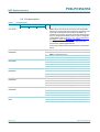
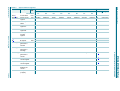
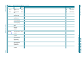
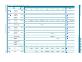
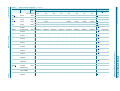
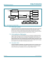
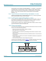
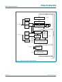
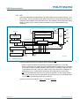
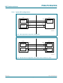
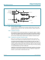
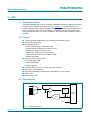
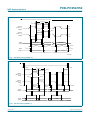
P89LPC952/954
NXP Semiconductors
8-bit microcontroller with 10-bit ADC
7.23 KBI
The Keypad Interrupt function is intended primarily to allow a single interrupt to be
generated when Port 0 is equal to or not equal to a certain pattern. This function can be
used for bus address recognition or keypad recognition. The user can configure the port
via SFRs for different tasks.
The Keypad Interrupt Mask Register (KBMASK) is used to define which input pins
connected to Port 0 can trigger the interrupt. The Keypad Pattern Register (KBPATN) is
used to define a pattern that is compared to the value of Port 0. The Keypad Interrupt Flag
(KBIF) in the Keypad Interrupt Control Register (KBCON) is set when the condition is
matched while the Keypad Interrupt function is active. An interrupt will be generated if
enabled. The PATN_SEL bit in the Keypad Interrupt Control Register (KBCON) is used to
define equal or not-equal for the comparison.
In order to use the Keypad Interrupt as an original KBI function like in 87LPC76x series,
the user needs to set KBPATN = 0FFH and PATN_SEL = 1 (not equal), then any key
connected to Port 0 which is enabled by the KBMASK register will cause the hardware to
set KBIF and generate an interrupt if it has been enabled. The interrupt may be used to
wake-up the CPU from Idle or Power-down modes. This feature is particularly useful in
handheld, battery-powered systems that need to carefully manage power consumption
yet also need to be convenient to use.
In order to set the flag and cause an interrupt, the pattern on Port 0 must be held longer
than six CCLKs.
7.24 Watchdog timer
The watchdog timer causes a system reset when it underflows as a result of a failure to
feed the timer prior to the timer reaching its terminal count. It consists of a programmable
12-bit prescaler, and an 8-bit down counter. The down counter is decremented by a tap
taken from the prescaler. The clock source for the prescaler is either the PCLK or the
nominal 400 kHz watchdog oscillator. The watchdog timer can only be reset by a
power-on reset. When the watchdog feature is disabled, it can be used as an interval timer
and may generate an interrupt. Figure 16 shows the watchdog timer in Watchdog mode.
Feeding the watchdog requires a two-byte sequence. If PCLK is selected as the watchdog
clock and the CPU is powered down, the watchdog is disabled. The watchdog timer has a
time-out period that ranges from a few µs to a few seconds. Please refer to the
P89LPC952/954 User’s Manual for more details.
P89LPC952_954_4
Product data sheet
© NXP B.V. 2008. All rights reserved.
Rev. 04 — 24 July 2008
42 of 69