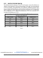
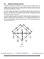
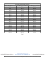
1
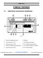
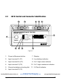
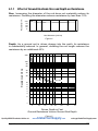
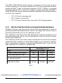
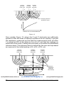
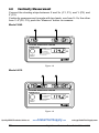
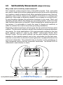
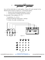
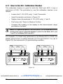
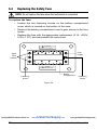
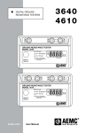
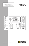
3640 4610 DIGITAL GROUND RESISTANCE TESTERS X Y C1 Z P2 C2 GROUND RESISTANCE TESTER MODEL 3640 X-Z Fault Ω Xv-Y Hi Resistance Xv-Y Hi Noise ! Press To Measure AUTORANGING REFER TO USER MANUAL FOR FAULT WARNING LIGHT EXPLANATIONS ® INSTRUMENTS X Xv C1 P1 Y Z P2 C2 GROUND RESISTANCE TESTER MODEL 4610 X-Z Fault Ω Xv-Y Hi Resistance Xv-Y Hi Noise ! Press To Measure REFER TO USER MANUAL FOR FAULT WARNING LIGHT EXPLANATIONS AUTORANGING ® INSTRUMENTS Quality AEMC Products Online at: ENGLISH www. GlobalTestSupply.com User Manual [email protected] Statement of Compliance Chauvin Arnoux®, Inc. d.b.a. AEMC® Instruments certifies that this instrument has been calibrated using standards and instruments traceable to international standards. We guarantee that at the time of shipping your instrument has met its published specifications. An NIST traceable certificate may be requested at the time of purchase, or obtained by returning the instrument to our repair and calibration facility, for a nominal charge. The recommended calibration interval for this instrument is 12 months and begins on the date of receipt by the customer. For recalibration, please use our calibration services. Refer to our repair and calibration section at www.aemc.com. Serial #: _________________________________ Catalog #: _______________________________ Model #: 3640 / 4610 Please fill in the appropriate date as indicated: Date Received: __________________________________ Date Calibration Due: ________________________ Chauvin Arnoux®, Inc. d.b.a AEMC® Instruments www.aemc.com Quality AEMC Products Online at: www. GlobalTestSupply.com [email protected] Table of Contents 1.INTRODUCTION................................................................................ 3 1.1 1.2 1.3 1.4 International Electrical Symbols.................................................3 Definition of Measurement Categories......................................4 Receiving Your Shipment...........................................................4 Ordering Information..................................................................4 1.4.1 Kits, Accessories and Replacement Parts.....................5 2. PRODUCT FEATURES....................................................................... 6 2.1 3640 Control and Connector Identification................................6 2.2 4610 Control and Connector Identification................................7 2.3 Fault Indicator LEDs..................................................................8 2.3.1 X-Z Fault........................................................................8 2.3.2 X-Y High Resistance (3640) Xv-Y High Resistance (4610)................................................ 8 2.3.3 X-Y High Noise (3640) Xv-Y High Noise (4610)....................................................8 2.4 Over-range Indication................................................................9 2.5 Fault LED Indication – Tips and Solutions.................................9 3.SPECIFICATIONS........................................................................... 10 3.1Electrical..................................................................................10 3.2 Mechanical............................................................................... 11 3.3Environmental.......................................................................... 11 3.4 Safety Specifications............................................................... 11 3.5 Auto-ranging............................................................................12 4.OPERATION................................................................................... 13 4.1 Grounding Electrode Resistance.............................................13 4.1.1 Effect of Ground Electrode Size and Depth on Resistance..............................................................15 4.1.2 Effects of Soil Resistivity on Ground Electrode Resistance...................................................................16 4.1.3 Factors Affecting Soil Resistivity..................................17 4.1.4 Effect of Ground Rod Depth on Resistance.................19 Quality AEMC Products Online at: www. GlobalTestSupply.com Digital Ground Resistance Tester Model 3640 and 4610 [email protected] 1 4.2 Ground Resistance Values......................................................21 4.3 Ground Resistance Testing Principle ......................................23 4.3.1 Position of Auxiliary Electrodes in Measurements.......24 4.4 Measuring Resistance of Ground Electrodes (62% Method)...25 4.4.1 Auxiliary Electrode Spacing.........................................27 4.5 Ground Resistance Measurement Procedure (3-Point)...........28 4.6 Multiple Electrode System.......................................................29 4.7 2-Point Measurement (Simplified Measurement).............. 31 4.8 Continuity Measurement..........................................................32 4.9 Soil Resistivity Measurements (Model 4610 Only)..................33 4.10Soil Resistivity Measurement Procedure (4-Point)..................34 4.11 How to Use 25Ω Calibration Checker......................................36 5.MAINTENANCE.............................................................................. 37 5.1 5.2 5.3 5.4 Warning...................................................................................37 Cleaning...................................................................................37 Replacing the Battery..............................................................37 Replacing the Safety Fuse.......................................................38 Repair and Calibration............................................................................39 Technical and Sales Assistance.............................................................39 Limited Warranty....................................................................................40 Warranty Repairs....................................................................................40 Quality AEMC Products Online at: 2 www. GlobalTestSupply.com [email protected] Digital Ground Resistance Tester Model 3640 and 4610 CHAPTER 1 INTRODUCTION WARNING “It should be impressed on all personnel that a lethal potential can exist between the station ground and a remote ground if a system fault involving the station ground occurs while tests are being made. Since one of the objects of tests on a station ground is the establishment of the location of an effectively remote point for both current and potential electrodes, the leads to the electrodes must be treated as though a possible potential could exist between these test leads and any point on the station ground grid.” - excerpted from IEEE Std. 81-1962 These safety warnings are provided to ensure the safety of personnel and proper operation of the instrument. • The instrument must not be operated beyond its specified operating range. • Safety is the responsibility of the operator. • All metal objects or wires connected to the electrical system should be assumed to be lethal until tested. Grounding systems are no exception. • Use extreme caution when using the instrument around energized electrical equipment. • Never attempt to use the instrument to twist or pry the ground electrode or ground wire away from the equipment being grounded. • The use of rubber gloves is an excellent safety practice even if the equipment is properly operated and correctly grounded. • Always inspect the instrument and leads prior to use. Replace any defective parts immediately. 1.1 International Electrical Symbols This symbol signifies that the instrument is protected by double or reinforced insulation. This symbol on the instrument indicates a WARNING and that the operator must refer to the user manual for instructions before operating the instrument. In this manual, the symbol preceding instructions indicates that if the instructions are not followed, bodily injury, installation/sample and product damage may result. Risk of electric shock. The voltage at the parts marked with this symbol may be dangerous. In conformity with WEEE 2002/96/EC Quality AEMC Products Online at: www. GlobalTestSupply.com Digital Ground Resistance Tester Model 3640 and 4610 [email protected] 3 1.2 Definition of Measurement Categories CAT I: For measurements on circuits not directly connected to the AC supply wall outlet such as protected secondaries, signal level, and limited energy circuits. CAT II: For measurements performed on circuits directly connected to the electrical distribution system. Examples are measurements on household appliances or portable tools. CAT III: For measurements performed in the building installation at the distribution level such as on hardwired equipment in fixed installation and circuit breakers. CAT IV: For measurements performed at the primary electrical supply (<1000V) such as on primary overcurrent protection devices, ripple control units, or meters. 1.3 Receiving Your Shipment Upon receiving your shipment, make sure that the contents are consistent with the packing list. Notify your distributor of any missing items. If the equipment appears to be damaged, file a claim immediately with the carrier and notify your distributor at once, giving a detailed description of any damage. Save the damaged packing container to substantiate your claim. 1.4 Ordering Information Ground Resistance Tester Model 3640............................. Cat. #2114.92 Includes soft carrying case, batteries and a user manual. Ground Resistance Tester Model 3640 Kit (150 ft).......... Cat. #2135.13 Includes ground tester, two 150 ft color-coded leads on spools (red/blue), one 30 ft lead (green), two T-shaped auxiliary ground electrodes, set of 5 spaded lugs, one 100 ft AEMC® tape measure, batteries, carrying bag and user manual. Ground Resistance Tester Model 3640 Kit (300 ft).......... Cat. #2135.14 Includes ground tester, two 300 ft color-coded leads on spools (red/blue), two 100 ft colorcoded leads (hand-tied, green/black), four T-shaped auxiliary ground electrodes, set of 5 spaded lugs, one 100 ft AEMC® tape measure, batteries, carrying bag and user manual. Ground Resistance Tester Model 3640 Kit (500 ft).......... Cat. #2135.15 Includes ground tester, two 500 ft color-coded leads on spools (red/blue), two 100 ft colorcoded leads (hand-tied, green/black), one 30 ft lead (green), four T-shaped auxiliary ground electrodes, set of 5 spaded lugs, one 100 ft AEMC® tape measure, batteries, carrying bag, and user manual. Ground Resistance Tester Model 4610............................. Cat. #2114.94 Includes soft carrying case, batteries and a user manual. www. Quality AEMC Products Online at: GlobalTestSupply.com 4 [email protected] Digital Ground Resistance Tester Model 3640 and 4610 Ground Resistance Tester Model 4610 Kit (150 ft).......... Cat. #2135.16 Includes ground tester, two 150 ft color-coded leads on spools (red/blue), one 30 ft lead (green), two T-shaped auxiliary ground electrodes, set of 5 spaded lugs, one 100 ft AEMC® tape measure, batteries, carrying bag and user manual. Ground Resistance Tester Model 4610 Kit (300 ft).......... Cat. #2135.17 Includes ground tester, two 300 ft color-coded leads on spools (red/blue), two 100 ft colorcoded leads (hand-tied, green/black), four T-shaped auxiliary ground electrodes, set of 5 spaded lugs, one 100 ft AEMC® tape measure, batteries, carrying bag and user manual. Ground Resistance Tester Model 4610 Kit (500 ft).......... Cat. #2135.18 Includes ground tester, two 500 ft color-coded leads on spools (red/blue), two 100 ft colorcoded leads (hand-tied, green/black), one 30 ft lead (green), four T-shaped auxiliary ground electrodes, set of 5 spaded lugs, one 100 ft AEMC® tape measure, batteries, carrying bag and user manual. 1.4.1 Kits, Accessories and Replacement Parts Test Kit for 3-Point Testing................................................ Cat. #2135.35 Includes two 150 ft color-coded leads on spools (red/blue), one 30 ft lead (green), two Tshaped auxiliary ground electrodes, set of 5 spaded lugs, one 100 ft AEMC® tape measure, carrying bag. Test Kit for 4-Point Testing................................................ Cat. #2135.36 Includes two 300 ft color-coded leads on spools (red/blue), two 100 ft color-coded leads (hand-tied, green/black), four T-shaped auxiliary ground electrodes, set of 5 spaded lugs, one 100 ft AEMC® tape measure, carrying bag. Test Kit for 4-Point Testing................................................ Cat. #2135.37 Includes two 500 ft color-coded leads on spools (red/blue), two 100 ft color-coded leads (hand-tied, green/black), one 30 ft lead (green), four T-shaped auxiliary ground electrodes, set of 5 spaded lugs, one 100 ft AEMC® tape measure, carrying bag. Test Kit for 3-Point Testing (Supplemental for 4-Point Testing).... Cat. #2135.38 Includes two 100 ft color-coded leads (hand-tied, green/black), one 30 ft lead (green), two T-shaped auxiliary ground electrodes, set of 5 spaded lugs, one 100 ft AEMC® tape measure, carrying bag. Set of 2, T-Shaped Auxiliary Ground Electrodes............. Cat. #2135.39 Ground Tester Video/Workbook Set................................. Cat. #2130.64 25Ω Calibration Checker.................................................... Cat. #2130.59 Tape Measure – AEMC 100 ft............................................. Cat. #2130.60 Fuse – Set of 5, 0.1A, >250V, 0.25 x 1.25"......................... Cat. #2970.12 Order Accessories and Replacement Parts Directly Online Check our Storefront at www.aemc.com/store for availability Quality AEMC Products Online at: www. GlobalTestSupply.com Digital Ground Resistance Tester Model 3640 and 4610 [email protected] 5 CHAPTER 2 PRODUCT FEATURES 2.1 3640 Control and Connector Identification 2 3 4 5 X Y Z C1 P2 C2 GROUND RESISTANCE TESTER MODEL 3640 X-Z Fault 6 Ω Xv-Y Hi Resistance 1 Xv-Y Hi Noise ! Press To Measure 10 9 AUTORANGING REFER TO USER MANUAL FOR FAULT WARNING LIGHT EXPLANATIONS 8 7 Figure 1 1. Press-to-Measure button 6. Display 2. Input terminal X (C1) 7. Low battery indicator 3. Input terminal Y (P2) 8. Xv-Y high noise indicator 4. Ground resistance shorting link 9. Xv-Y high resistance indicator 5. Input terminal Z (C2) 10. X-Z fault indicator Quality AEMC Products Online at: 6 www. GlobalTestSupply.com [email protected] Digital Ground Resistance Tester Model 3640 and 4610 2.2 4610 Control and Connector Identification 2 3 4 5 6 X Xv Y Z C1 P1 P2 C2 GROUND RESISTANCE TESTER MODEL 4610 X-Z Fault 7 Ω Xv-Y Hi Resistance 1 Xv-Y Hi Noise ! Press To Measure 11 10 AUTORANGING REFER TO USER MANUAL FOR FAULT WARNING LIGHT EXPLANATIONS 9 8 Figure 2 1. Press-to-Measure button 7. Display 2. Input terminal X (C1) 8. Low battery indicator 3. Input terminal Xv (P1) 9. Xv-Y high noise indicator 4. Input terminal Y (P2) 10. Xv-Y high resistance indicator 5. Ground resistance shorting link 11. X-Z fault indicator 6. Input terminal Z (C2) Quality AEMC Products Online at: www. GlobalTestSupply.com Digital Ground Resistance Tester Model 3640 and 4610 [email protected] 7 2.3 Fault Indicator LEDs The three indicators described below confirm the correct measurement being taken if none of them are lit. 2.3.1 X-Z Fault This LED signals that voltage between terminals X and Z exceeds 30V peak. There are four possible causes: • the resistance of the current circuit between X and Z is too high • interference voltage in the current circuit is too high • the fuse is blown • the circuit is open (lead not connected) 2.3.2 X-Y High Resistance (3640) - Xv-Y High Resistance (4610) This LED signals that the resistance in the voltage circuit (between Xv and Y or X and Y) is too high (approx 50kΩ) or that the circuit may be open. • Flashing will continue throughout the measurement, even if the resistance drops below the threshold (e.g. after reconnecting or lowering auxiliary rod resistance). • In this case, you must release the push-button and press again after the fault has been corrected. • Occasionally, a stray voltage above 6VDC may also set off this light. • Check the leads for a possible solution. 2.3.3 X-Y High Noise (3640) - Xv-Y High Noise (4610) This LED signals the presence of excessive noise (approx 13V peak) in the voltage circuit (between Xv and Y or X and Y). • One remedy is to use shielded leads from the instrument to the auxiliary electrodes. • Connect all the shields to the rod under test. Quality AEMC Products Online at: 8 www. GlobalTestSupply.com [email protected] Digital Ground Resistance Tester Model 3640 and 4610 2.4 Over-range Indication Over-range is indicated when the display reads 1, or when the display is blinking and the indicator is lit. 2.5 Fault LED Indication – Tips and Solutions The LED indicators show excessive electrode resistance and excessive transient noise and/or stray current. In the event of an incorrect measurement indication: • Improve the quality of the connection to earth of auxiliary ground electrodes Y and Z. Z is the most likely source of problems caused by excessive electrode resistance. • Check connections for continuity between leads and electrodes. • Be sure that electrodes are properly inserted; they should be buried as much as possible. • If high electrode resistance still exists after properly inserting auxiliary electrodes into the earth, try pouring water on and around the auxiliary electrodes. This will improve their electrical connection to earth. • If stray currents are suspected, one solution to reduce their influence is to move both Y and Z electrodes in an arc relative to the X electrode (try, e.g., a 90° shift), and test again. • Display of 0.00: Xv and Y are short-circuited. • Display of <0: X and Z or Xv and Y rods are reversed. NOTE: Accuracy may be affected by auxiliary ground rod (Ry, Rz) resistance levels and by stray signal levels (earth currents). Quality AEMC Products Online at: www. GlobalTestSupply.com Digital Ground Resistance Tester Model 3640 and 4610 [email protected] 9 CHAPTER 3 SPECIFICATIONS 3.1Electrical Measurement Ranges: Auto-ranging 0 to 2000Ω Range Measurement Resolution Test Current Accuracy Open Voltage 20Ω 200Ω 0 to 19.99Ω 20 to 199.9Ω 10mΩ 100mΩ 10mA 1mA ± 2% of Reading ± 1ct <42V peak 2000Ω 200 to 1999Ω 1Ω 0.1mA ± 5% of Reading ± 3cts Operating Frequency: 128Hz square wave Max. Auxiliary Rod Resistance: Range Current Circuit Voltage Circuit 20Ω 3kΩ 200Ω 30kΩ 50kΩ 2000Ω 50kΩ Response Time: Approximately 6 seconds for a stabilized measurement Interference: Models 3640 & 4610 are designed to reject high levels of interference voltage (DC, 50/60Hz, harmonics) • DC voltage in series with X: 20V • AC voltage in series with Y: 13V peak • AC voltage in series with Z: 32V peak Accuracies and specifications are given for an ambient temperature of 23°C ± 3°, RH of 45 to 55%, battery power at 8V, auxiliary resistance at the measurement terminals <200Ω, no stray voltage and a magnetic field from 0 to 40A/m. Power Source: Eight 1.5V “AA” batteries; Alkaline recommended. Battery Life: 1800 15-second measurements Low Battery Indicator: If the “Lo Bat” indicator lights up, the batteries are losing power. The available operating time remaining is 100 15-second measurements (approx). Fuse Protection: breaking www. Quality AEMC Products Online at:High capacity - 0.1A,.com >250V, [email protected] 0.25 x 1.25" GlobalTestSupply 10 Digital Ground Resistance Tester Model 3640 and 4610 3.2Mechanical Connection: Color-coded terminals accept spade lugs with minimum gap of 6mm or standard 4mm banana jacks Display: 7 segment LCD, .71" (18mm) high (3-1/2 digit); 2000cts LCD also indicates overrange, test lead shorts and lead reversals. Dimensions: 8.7 x 5.4 x 5.9" (220 x 136 x 150mm) Weight: 2.9 lbs (1.3kg) Case: Heavy-duty, ABS Colors: Case - safety yellow; Front panel - gray Mechanical Shock: IEC 68-2-27 Vibration: IEC 68-2-6 Drop Test: IEC 68-2-32 Case Material: UL94 Environmental: O-ring sealed against dust and water to IP50 3.3Environmental Operating Temperature: 14° to 131°F (-10° to 55°C); 0 to 90% RH Storage Temperature: -40° to 158°F (-40° to 70°C); 0 to 90% RH with batteries removed 3.4 Safety Specifications Electrical: EN 61010-1, CAT lII, Pollution Degree 2, 42V Electromagnetic Compatibility: Emission: EN 61326-1 Immunity: EN 61326-1 *Specifications are subject to change without notice. Quality AEMC Products Online at: www. GlobalTestSupply.com Digital Ground Resistance Tester Model 3640 and 4610 [email protected] 11 3.5Auto-ranging The selection of the measurement current is depending on the resistance to measure. When the instrument is turned ON, the measurement starts on the smallest current range (100µA). If the measurement is between 185 and 1950cts, the range stays the same (100µA). If the measurement is under 185cts, the current is multiplied by 10 (within 10mA max). If it is above 1950cts, the current is divided by 10 (without going under 100µA). This is done to avoid switching back and forth between ranges when you are measuring 190W. It is possible to display 190.0 or 190W depending on the automatic range selection. Quality AEMC Products Online at: 12 www. GlobalTestSupply.com [email protected] Digital Ground Resistance Tester Model 3640 and 4610 CHAPTER 4 OPERATION 4.1 Grounding Electrode Resistance Figure 3 illustrates a grounding rod. The resistance of the electrode has the following components: • the resistance of the metal and that of the connection to it • the contact resistance of the surrounding earth to the electrode • the resistance in the surrounding earth More specifically: A) Grounding electrodes are usually made of a very conductive metal (copper) with adequate cross sections so that overall resistance is negligible. B) The National Institute of Standard and Technology (N.I.S.T.) has demonstrated that the resistance between the electrode and the surrounding earth is negligible if the electrode is free of paint, grease or other coating, and if the earth is firmly packed. Ground Rod and Clamp Contact Resistance Between Rod and Soil Concentric Shells of Earth Quality AEMC Products Online at: www. GlobalTestSupply .com Figure 3 Digital Ground Resistance Tester Model 3640 and 4610 [email protected] 13 C) The only component remaining is the resistance of the surrounding earth. The electrode can be thought of as being surrounded by concentric shells of earth or soil, all of the same thickness. The closer the shell to the electrode, the smaller its surface; hence, the greater its resistance. The farther away the shells are from the electrode, the greater the surface of the shell; hence, the lower the resistance. Eventually, adding shells at a distance from the grounding electrode will no longer noticeably affect the overall earth resistance surrounding the electrode. The distance at which this effect occurs is referred to as the effective resistance area and is directly dependent on the depth of the grounding electrode. In theory, the ground resistance may be derived from the general formula: R = ρ L A Resistance = Resistivity x Length Area This formula clearly illustrates why the shells of concentric earth decrease in resistance the farther they are from the ground rod: R = Resistivity of Soil x Thickness of Shell Area In the case of ground resistance, uniform earth (or soil) resistivity throughout the volume is assumed, although this is seldom the case in nature. The equations for systems of electrodes are very complex and often expressed only as approximations. The most commonly used formula for single ground electrode systems, developed by Professor H. R. Dwight of the Massachusetts Institute of Technology, follows: R = ρ 2πL {(In 4L) -1} r R = resistance in ohms of the ground rod to the earth (or soil) L = grounding electrode length r = grounding electrode radius ρ = average resistivity in ohms-cm Quality AEMC Products Online at: 14 www. GlobalTestSupply.com [email protected] Digital Ground Resistance Tester Model 3640 and 4610 4.1.1 Effect of Ground Electrode Size and Depth on Resistance Resistance in % Size: Increasing the diameter of the rod does not materially reduce its resistance. Doubling the diameter reduces resistance by less than 10%. 100 75 50 25 0 1/2 5/8 3/4 1 1 1/4 1 1/2 1 3/4 Rod Diameter (inches) Figure 4 Depth: As a ground rod is driven deeper into the earth, its resistance is substantially reduced. In general, doubling the rod length reduces the resistance by an additional 40%. 200 100 Resistance in Ohms 80 60 40 30 20 1" dia. 10 1/2" dia. 8 6 5 4 3 2 1 5 15 25 35 40 50 60 70 Driven Depth in Feet Ground Resistance Versus Ground Rod Depth Quality AEMC Products Online at: www. Figure 5 GlobalTestSupply.com Digital Ground Resistance Tester Model 3640 and 4610 [email protected] 15 The NEC® 2008 250.52 (A)(5) requires a minimum of 8 ft (2.4m) to be in contact with the soil. The most common is a 10 ft (3m) cylindrical rod which meets the NEC® code. A minimum diameter of 5/8" (1.59cm) is required for steel rods and 1/2" (1.27cm) for copper or copper clad steel rods NEC® 2008 250.52(A)(5)(a)(b). Minimum practical diameter for driving limitations for 10 ft (3m) rods are: • 1/2" (1.27cm) in average soil • 5/8" (1.59cm in moist soil • 3/4" (1.91cm) in hard soil or more than 10 ft driving depths 4.1.2 Effects of Soil Resistivity on Ground Electrode Resistance Dwight’s formula, cited previously, shows that the resistance to earth of grounding electrodes depends not only on the depth and surface area of grounding electrodes but on soil resistivity as well. Soil resistivity is the key factor that determines what the resistance of a grounding electrode will be, and to what depth it must be driven to obtain low ground resistance. The resistivity of the soil varies widely throughout the world and changes seasonally. Soil resistivity is determined largely by its content of electrolytes, consisting of moisture, minerals and dissolved salts. A dry soil has high resistivity if it contains no soluble salts. Resistivity, Ω-cm Soil Minimum Average Maximum Ashes, cinders, brine, waste 590 2,370 7,000 Clay, shale, gumbo, loam 340 4,060 16,300 1,020 15,800 135,000 59,000 94,000 458,000 Same, with varying proportions of sand and gravel Gravel, sand, stones with little clay or loam Table 1 Quality AEMC Products Online at: 16 www. GlobalTestSupply.com [email protected] Digital Ground Resistance Tester Model 3640 and 4610 4.1.3 Factors Affecting Soil Resistivity Two samples of soil, when thoroughly dried, may become in fact very good insulators, having a resistivity in excess of 109 ohm-centimeters. The resistivity of the soil sample is seen to change quite rapidly until approximately twenty percent or greater moisture content is reached. Resistivity, Ω-cm Moisture content, % by weight Top Soil Sandy Loam 0 > 109 > 109 2.5 250,000 150,000 5 165,000 43,000 10 53,000 18,500 15 19,000 10,500 20 12,000 6,300 30 6,400 4,200 Table 2 The resistivity of the soil is also influenced by temperature. Table 3 shows the variation of the resistivity of sandy loam, containing 15.2% moisture, with temperature changes from 20° to -15°C. In this temperature range the resistivity is seen to vary from 7,200 to 330,000 ohm-centimeters. Quality AEMC Products Online at: www. GlobalTestSupply.com Digital Ground Resistance Tester Model 3640 and 4610 [email protected] 17 Temperature °C °F Resistivity Ω-cm 20 68 7,200 10 50 9,900 0 32 (water) 13,800 0 32 (ice) 30,000 -5 23 79,000 -15 14 330,000 Table 3 Because soil resistivity directly relates to moisture content and temperature, it is reasonable to assume that the resistance of any grounding system will vary throughout the different seasons of the year. Such variations are shown in Figure 6 below. Since both temperature and moisture content become more stable at greater distances below the surface of the earth, it follows that a grounding system (to be most effective at all times) should be constructed with the ground rod driven down a considerable distance below the surface of the earth. Best results are obtained if the ground rod reaches the water table. 80 60 Curve 1 40 20 July May Mar. Jan. Nov. Sept. July May Curve 2 Mar. Jan. 0 Figure 6 Seasonal variation of earth resistance with an electrode of 3/4" pipe in rather stony clay soil. Depth of electrode in earth is 3 ft for Curve 1, and 10 ft for Curve 2. In some locations, the resistivity of the earth is so high that low-resistance grounding can be obtained only at considerable expense and with an elaborate grounding system. In such situations, it may be economical to use a ground rod system of Quality AEMC Products Online at: 18 www. GlobalTestSupply.com [email protected] Digital Ground Resistance Tester Model 3640 and 4610 limited size and to reduce the ground resistivity by periodically increasing the soluble chemical content of the soil. Table 4 shows the substantial reduction in resistivity of sandy loam brought about by an increase in chemical salt content. The Effect of Salt* Content on the Resistivity of Soil (sandy loam, moisture content, 15% by weight, temperature 17°C) Added Salt % by weight of moisture Resistivity (Ohm-centimeters) 0 0.1 1.0 5 10 20 10,700 1,800 460 190 130 100 Table 4 Chemically treated soil is also subject to considerable variation of resistivity with changes in temperature, as shown in Table 5. If salt treatment is employed, it is, of course, necessary to use ground rods which will resist chemical corrosion. The Effect of Temperature on the Resistivity of Soil Contining Salt* (sandy loam, 20% moisture; salt 5% of weight of moisture) Temperature °C 20 10 0 -5 -13 Resistivity (Ohm-centimeters) 110 142 190 312 1440 Table 5 *Such as copper sulfate, sodium carbonate and others. Salts must be EPA or local ordinance approved prior to use. 4.1.4 Effect of Ground Rod Depth on Resistance Quality AEMC Products Online at: www. GlobalTestSupply.com Digital Ground Resistance Tester Model 3640 and 4610 [email protected] 19 To assist the engineer in determining the approximate ground rod depth required to obtain a desired resistance, a device called the Grounding Nomograph may be used. The Nomograph, shown on the following page, indicates that to obtain a grounding resistance of 20 ohms in a soil with a resistivity of 10,000 ohm-centimeters, a 5/8" OD rod must be driven 20 ft. Note that the values indicated on the Nomograph are based on the assumption that the soil is homogeneous and, therefore, has uniform resistivity (Figure 7). The Nomograph value is an approximation. Grounding Nomograph Ground Rod Resistance-Ohms 100 80 60 40 20 10 8 6 Soil Resistivity (Ohm-centimeters) R 80 90 70 100000 50 40000 30 20000 15 9 7 Rod Depth Feet D K 100 P 60 40 50000 30000 15000 2000 8 50 6 30 4 7 5 3 2 15 5000 10 1.5 1 3/4 3000 5 1000 5/8 1/2 4 500 5 DIA 70 20 10000 4000 90 Rod Diameter Inches 3 2 4 1/4 3 1 2 1 Figure 7 1. Select required resistance on R scale. 2. Select apparent resistivity on P scale. 3. Lay straightedge on R and P scale, and allow to intersect with K scale. 4. Mark K scale point. 5. Lay straightedge on K scale point and DIA scale, and allow to intersect with D scale. 6. Point on D scale will be rod depth required for resistance on R scale. Quality AEMC Products Online at: 20 www. GlobalTestSupply.com [email protected] Digital Ground Resistance Tester Model 3640 and 4610 4.2 Ground Resistance Values NEC® 2008 article 250.56 regarding the resistance of rod, pipe and plate electrodes states that if the rod, pipe, or plate does not have a resistance of 25Ω or less to ground shall be augmented by one additional electrode of any of the types specified by 250.52 (A)(4) through (A)(8). Where multiple rod, pipe or plate electrodes are installed to meet the requirements of the section, they shall not be less than 6 feet apart. FPN: The paralleling efficiency of rods longer than 8 feet is improved by spacing greater than 6 feet apart. The National Electrical Code® (NEC®) states that the resistance to ground shall not exceed 25Ω. This is an upper limit and guideline, since much lower resistance is required in many instances. “How low in resistance should a ground be?” An arbitrary answer to this in ohms is difficult. The lower the ground resistance, the safer, and for positive protection of personnel and equipment, it is worth the effort to aim for less than one ohm. It is generally impractical to reach such a low resistance along a distribution system or a transmission line or in small substations. In some regions, resistances of 5Ω or less may be obtained without much trouble. In others, it may be difficult to bring resistance of driven grounds below 100Ω. Accepted industry standards stipulate that transmission substations should be designed not to exceed one ohm resistance. In distribution substations, the maximum recommended resistance is 5Ω. In most cases, the buried grid system of any substation will provide the desired resistance. In light industrial or in telecommunications central offices, 5Ω is often the accepted value. For lightning protection, the arresters should be coupled with a maximum ground resistance of 1Ω. These parameters can usually be met with the proper application of basic grounding theory. There will always exist circumstances which will make it difficult to obtain the ground resistance required by the NEC®. When these situations develop, several methods of lowering the ground resistance can be employed. These include parallel rod systems, deep driven rod systems utilizing sectional rods and chemical treatment of the soil. Additional methods, discussed in other published data, are buried plates, buried conductors (counterpoise), electrically connected building steel, and electrically connected concrete reinforced steel. Electrically connecting to existing water and gas distribution systems was www.low GlobalTestSupply [email protected] yield ground resistance;.com however, recent design Quality AEMC Online at:to oftenProducts considered Digital Ground Resistance Tester Model 3640 and 4610 21 changes utilizing non-metallic pipes and insulating joints have made this method of obtaining a low resistance ground questionable and in many instances unreliable. Ground rods, of course, will be required in high voltage transmission lines, where maximum resistance of 15 ohms is recommended; and in distribution lines, where maximum resistance of 25 ohms is preferred. All electrical systems constructed in accordance with the National Electrical Code®, should not exceed 25 ohms. The measurement of ground resistances may only be accomplished with specially designed test equipment. Most instruments use the Fall of Potential principle of alternating current (AC) circulating between an auxiliary electrode and the ground electrode under test; the reading will be given in ohms and represents the resistance of the ground electrode to the surrounding earth. AEMC® Instruments has also recently introduced a clamp-on ground resistance tester. Note: The National Electrical Code® and NEC® are registered trademarks of the National Fire Protection Association. Quality AEMC Products Online at: 22 www. GlobalTestSupply.com [email protected] Digital Ground Resistance Tester Model 3640 and 4610 4.3 Ground Resistance Testing Principle (Fall-of-Potential — 3-Point Measurement) Three-point measurement is used to measure resistance to ground of ground rods and grids. The potential difference between rods X and Y is measured by a voltmeter, and the current flow between rods X and Z is measured by an ammeter. By Ohm’s Law E = RI or R = E/I, we may obtain the ground electrode resistance R. If E = 20V and I = 1A, then: E 20 R = = = 20 ohms I 1 It is not necessary to carry out all the measurements when using a ground tester. The ground tester will measure directly by generating its own current and displaying the resistance of the ground electrode. CURRENT SUPPLY AMMETER (I) VOLTMETER (E) GROUND ELECTRODE UNDER TEST X AUXILIARY POTENTIAL ELECTRODE Y AUXILIARY CURRENT ELECTRODE Z R EARTH Figure 8 NOTE: Terminals X and Xv are shorted together in three-point measurement Quality AEMC Products Online at: www. GlobalTestSupply.com Digital Ground Resistance Tester Model 3640 and 4610 [email protected] 23 4.3.1 Position of the Auxiliary Electrodes in Measurements The goal in precisely measuring the resistance to ground is to place the auxiliary current electrode Z far enough from the ground electrode under test so that the auxiliary potential electrode Y will be outside of the effective resistance areas of both the ground electrode and the auxiliary current electrode. The best way to find out if the auxiliary potential rod Y is outside the effective resistance areas is to move it between X and Z and to take a reading at each location. If the auxiliary potential rod Y is in an effective resistance area (or in both if they overlap), by displacing it, the readings taken will vary noticeably in value. Under these conditions, no exact value for the resistance to ground may be determined. X Y' Y Y'' Z Resistance Effective Resistance Areas (Overlapping) Reading Variation X-Y Distance Figure 9 On the other hand, if the auxiliary potential rod Y is located outside of the effective resistance areas, as Y is moved back and forth the reading variation is minimal. The readings taken should be relatively close to each other, and are the best values for the resistance to ground of the ground X. The readings should be plotted to ensure that they lie in a “plateau” region as shown in Figure 10. X Y Y Y'' Effective Resistance Areas (No Overlap) Resistance Quality AEMC Products Online at: 24 Z Reading Variation www. X-Y Distance GlobalTestSupply .com Figure 10 [email protected] Digital Ground Resistance Tester Model 3640 and 4610 4.4 Measuring Resistance of Ground Electrodes (62% Method) The 62% method has been adopted after graphical consideration and after actual test. It is the most accurate method but is limited by the fact that the ground tested is a single unit. This method applies only when all three electrodes are in a straight line and the ground is a single electrode, pipe, or plate, etc., as in Figures 11 and 12. Model 3640 X C1 Xv Y Z P1 P2 C2 GROUND RESISTANCE TESTER MODEL 4610 X-Z Fault Xv-Y Hi Resistance Xv-Y Hi Noise ! Ground Strip Press To Measure REFER TO USER MANUAL FOR FAULT WARNING LIGHT EXPLANATIONS 46.9 Ω AUTORANGING ® INSTRUMENTS Z Electrode Y Electrode Alligator Clips Ground Rod -10% 3rd Measurement Ground Rod X 0% +10% 2nd Measurement Y Electrode Y 52% 62% 72% Z Electrode Z 100% of distance between X and Z Figure 11 Model 4610 X Xv Y Z C1 P1 P2 C2 GROUND RESISTANCE TESTER MODEL 4610 X-Z Fault Ω Xv-Y Hi Resistance Xv-Y Hi Noise Ground Strip ! Press To Measure REFER TO USER MANUAL FOR FAULT WARNING LIGHT EXPLANATIONS AUTORANGING ® INSTRUMENTS Y Electrode Z Electrode Alligator Clips Ground Rod Figure 12 Consider Figure 13, which shows the effective resistance areas (concentric shells) of the ground electrode X and of the auxiliary current electrode Z. The resistance areas overlap. If readings were taken by moving the auxiliary potential electrode Y towards either X or Z, the reading differentials would be great and one could not obtain a reading within a reasonable band of tolerance. The sensitive areas overlap and act constantly to increase www.GlobalTestSupply .com Quality AEMC Products Online at: [email protected] resistance as Y is moved away from X. Digital Ground Resistance Tester Model 3640 and 4610 25 Ground Electrode Under Test Auxiliary Potential Electrode X Y Auxiliary Current Electrode Z Resistance Overlapping Effective Resistance Areas Distance from Y to Ground Electrode Figure 13 Now consider Figure 14, where the X and Z electrodes are sufficiently spaced so that the areas of effective resistance do not overlap. If we plot the resistance, measured we find that the measurements level off when Y is placed at 62% of the distance from X to Z, and that the readings on either side of the initial Y setting are most likely to be within the established tolerance band. This tolerance band is defined by the user and expressed as a percent of the initial reading: ±2%, ±5%, ±10%, etc. Auxiliary Potential Electrode Ground Electrode Under Test X Auxiliary Current Electrode Y Z D Resistance 62% of D Quality AEMC Products Online at: 26 38% of D Resistance of Auxiliary Current Electrode Effective Resistance Areas Do Not Overlap Resistance of Earth Electrode Distance from Y to Ground Electrode www. GlobalTestSupply.com Figure 14 [email protected] Digital Ground Resistance Tester Model 3640 and 4610 4.4.1 Auxiliary Electrode Spacing No definite distance between X and Z can be given, since this distance is relative to the diameter of the electrode tested, its length, the homogeneity of the soil tested, and particularly, the effective resistance areas. However, an approximate distance may be determined from the following chart which is given for a homogeneous soil and an electrode of 1" in diameter. (For a diameter of 1/2", reduce the distance by 10%; for a diameter of 2" increase the distance by 10%.) Approximate Distance to Auxiliary Electrodes Using the 62% Method Depth Driven 6 ft 8 ft 10 ft 12 ft 18 ft 20 ft 30 ft Distance to Y 45 ft 50 ft 55 ft 60 ft 71 ft 74 ft 86 ft Distance to Z 72 ft 80 ft 88 ft 96 ft 115 ft 120 ft 140 ft Table 6 Quality AEMC Products Online at: www. GlobalTestSupply.com Digital Ground Resistance Tester Model 3640 and 4610 [email protected] 27 4.5 Ground Resistance Measurement Procedure (3-Point) X Y Z C1 P2 C2 GROUND RESISTANCE TESTER MODEL 3640 X-Z Fault Ω Xv-Y Hi Resistance Xv-Y Hi Noise Ground Strip ! Press To Measure REFER TO USER MANUAL FOR FAULT WARNING LIGHT EXPLANATIONS AUTORANGING ® INSTRUMENTS Z Electrode Y Electrode Alligator Clips Ground Rod Figure 15 WARNING: Use extreme caution when disconnecting the ground connection from the rest of the circuit. Current may be flowing and a dangerous potential could exist between the disconnected wires. • X and Xv (C1, P1) are shorted • Disconnect shorting link between Y and Z (C2, P2) • Connect X to the ground rod to be tested • Connect Y (P2) to the central electrode • Connect Z (C2) to the outer electrode • Depress the “Measure” button to measure ground resistance Quality AEMC Products Online at: 28 www. GlobalTestSupply.com [email protected] Digital Ground Resistance Tester Model 3640 and 4610 4.6 Multiple Electrode System A single driven ground electrode is an economical and simple means of making a good ground system, but sometimes a single rod will not provide sufficient low resistance, and several ground electrodes will be driven and connected in parallel by a cable. Very often when two, three or four ground electrodes are used, they are driven in a straight line. When four or more are used, a hollow square configuration is used and the ground electrodes are still connected in parallel and equally spaced (Figure 16). In multiple electrode systems, the 62% method electrode spacing may no longer be applied directly. The distance of the auxiliary electrodes is now based on the maximum grid distance (e.g., in a square, the diagonal; in a line, the total length). A square having a side of 20 ft will have a diagonal of approximately 28 ft. a a a a DIAGONAL DIAGONAL Figure 16 Quality AEMC Products Online at: www. GlobalTestSupply.com Digital Ground Resistance Tester Model 3640 and 4610 [email protected] 29 Multiple Electrode System Max Grid Distance 6 ft 8 ft 10 ft 12 ft 14 ft 16 ft 18 ft 20 ft 30 ft 40 ft 50 ft 60 ft 80 ft 100 ft 120 ft 140 ft 160 ft 180 ft 200 ft Distance to Y 78 ft 87 ft 100 ft 105 ft 118 ft 124 ft 130 ft 136 ft 161 ft 186 ft 211 ft 230 ft 273 ft 310 ft 341 ft 372 ft 390 ft 434 ft 453 ft Distance to Z 125 ft 140 ft 160 ft 170 ft 190 ft 200 ft 210 ft 220 ft 260 ft 300 ft 340 ft 370 ft 440 ft 500 ft 550 ft 600 ft 630 ft 700 ft 730 ft Table 7 Quality AEMC Products Online at: 30 www. GlobalTestSupply.com [email protected] Digital Ground Resistance Tester Model 3640 and 4610 4.7 2-Point Measurement (Simplified Measurement) This is an alternative method to three-point measurement when an excellent ground is already available. In congested areas where finding room to drive the two auxiliary ground electrodes may be a problem, the two-point measurement method may be applied. The reading obtained will be that of the two grounds in series. Therefore, the water pipe or other ground must be very low in resistance so that it will be negligible in the final measurement. The lead resistances will also be measured and should be deducted from the final measurement. This method is not as accurate as three-point methods (62% method), as it is particularly affected by the distance between the tested electrode and the dead ground or water pipe. This method should not be used as a standard procedure, but rather as a backup in tight areas. See Figure 17. Procedure: • Short X and Xv (C1, P1) • Short Y and Z (P2, C2) • Connect X to ground rod to be measured • Connect Z to an electrode • Measure as in the three-point method Grounding conductor Auxiliary rod (Y-Z shorted) Terminals shorted Ground level Utility pole X Xv Y Z C1 P1 P2 C2 GROUND RESISTANCE TESTER MODEL 4610 X-Z Fault Ground rod Butt plate Xv-Y Hi Resistance Xv-Y Hi Noise ! Press To Measure REFER TO USER MANUAL FOR FAULT WARNING LIGHT EXPLANATIONS 25.4 Ω AUTORANGING ® INSTRUMENTS Quality AEMC Products Online at: www. GlobalTestSupply.com Figure 17 Digital Ground Resistance Tester Model 3640 and 4610 [email protected] 31 4.8 Continuity Measurement Connect the shorting strips between X and Xv (C1, P1), and Y (P2) and Z (C2). Continuity measurement is made with two leads, one from X–Xv, the other from Y–Z (P2, C2); push the “Measure” button to measure. Model 3640 X Y Z C1 P2 C2 GROUND RESISTANCE TESTER MODEL 3640 X-Z Fault Ω Xv-Y Hi Resistance Xv-Y Hi Noise ! Press To Measure AUTORANGING REFER TO USER MANUAL FOR FAULT WARNING LIGHT EXPLANATIONS ® INSTRUMENTS Figure 18 Model 4610 X Xv Y Z C1 P1 P2 C2 GROUND RESISTANCE TESTER MODEL 4610 X-Z Fault Ω Xv-Y Hi Resistance Xv-Y Hi Noise ! Press To Measure REFER TO USER MANUAL FOR FAULT WARNING LIGHT EXPLANATIONS AUTORANGING ® INSTRUMENTS Figure 19 Quality AEMC Products Online at: 32 www. GlobalTestSupply.com [email protected] Digital Ground Resistance Tester Model 3640 and 4610 4.9 Soil Resistivity Measurements (Model 4610 Only) Why make soil resistivity measurements? Soil resistivity measurements have a threefold purpose. First, such data are used to make sub-surface geophysical surveys as an aid in identifying ore locations, depth to bedrock and other geological phenomena. Second, resistivity has a direct impact on the degree of corrosion in underground pipelines. A decrease in resistivity relates to an increase in corrosive activity and therefore dictates the protective treatment to be used. Third, soil resistivity directly affects the design of a grounding system, and it is to that task that this discussion is directed. When designing an extensive grounding system, it is advisable to locate the area of lowest soil resistivity in order to achieve the most economical grounding installation. Resistivity measurements are of two types, the two point and the four point method. The two point method is simply the resistance measured between two points. For most applications, the most accurate method is the four point method, which is used by the AEMC® Instruments Model 4610 Ground Tester. The four point method, as the name implies, requires the insertion of four equally spaced, and in-line, electrodes into the test area. A known current from a constant current generator is passed between the outermost electrodes. The potential drop (a function of the resistance) is then measured across the two innermost electrodes. The Model 4610 is calibrated to read directly in ohms. X Xv C1 P1 Y Z P2 C2 GROUND RESISTANCE TESTER MODEL 4610 X-Z Fault Xv-Y Hi Resistance Xv-Y Hi Noise ! Press To Measure REFER TO USER MANUAL FOR FAULT WARNING LIGHT EXPLANATIONS 225 Ω AUTORANGING ® INSTRUMENTS X electrode b< a 20 Quality AEMC Products Online at: a www. Xv electrode a Y electrode a Figure 20 GlobalTestSupply .com Digital Ground Resistance Tester Model 3640 and 4610 Z electrode [email protected] 33 4.10 Soil Resistivity Measurement Procedure (4-Point) Assuming that the objective is low resistivity, preference should be given to an area containing moist loam as opposed to a dry sandy area. Consideration must also be given to the depth at which resistivity is required. • Disconnect the shorting strip from the X and Xv terminals. • Arrange the electrodes in a straight line. Be sure that distances between electrodes are identical: e.g. 3 meters between each electrode (See Figure 20). • The distance between poles is proportional to the average depth of the soil sample you wish to make. • The electrodes should be placed at a depth of approximately 6 inches (0.15 meters), so that the depth is approximately 1/20th of the distance between electrodes. • Use leads to connect the X, Xv, Y, and Z electrodes to the respective terminals on the Digital Ground Resistance Tester. • Press the “Measure” button. • Read the resistance level (R) indicated on the display. • In the event of difficulties in performing measurements, consult the previous instructions concerning ground resistance measurements. • Apply the following formula in order to determine resistivity (ρ): ρ = 2π x R x A A = distance between electrodes in meters ρ = resistivity in Ω meters R = ohms reading obtained on Model 4610 Example 1: For measurement performed in soil with a high limestone content, the reading is R = 225Ω, with A = 3 meters. ρ = 2π x 225Ω x 3m ρ = 4239Ωm Example 2: After inspection, the area to be investigated has been narrowed down to a plot of ground approximately 75 square feet (22.5 m2). Assume that you need to determine the resistivity at a depth of 15 feet (457 cm). The distance “A” between the electrodes must then be equivalent to the depth at which average resistivity is to be determined (15 ft, or 450 cm). Using the more simplified Wenner formula (ρ = 2πAR), the electrode depth must then be 1/20th of the electrode spacing or 8⅞" (22.5cm). If the electrode depth is greater than 1/20th of the electrode spacing, the following formula must be used: Quality AEMC Products Online at: 34 www. GlobalTestSupply.com [email protected] Digital Ground Resistance Tester Model 3640 and 4610 ρ = 2A (A2 + 4B2) 1+ 4πAR 2A (4A2 + 4B2) Lay out the electrodes in a grid pattern (Figure 22) and connect to the Model 4610 as shown in Figure 21. Proceed as follows: • Remove the shorting strip between X and Xv • Connect all four auxiliary ground electrodes For example, if the reading is R = 15, ρ (resistivity) = 2π x R x A A (distance between electrodes) = 450 cm ρ = 6.28 x 15 x 450 = 42,390 Ω-cm A A X Xv Y Z C1 P1 P2 C2 A GROUND RESISTANCE TESTER MODEL 4610 X Xv Y Z X-Z Fault Ω Xv-Y Hi Resistance Xv-Y Hi Noise ! Press To Measure REFER TO USER MANUAL FOR FAULT WARNING LIGHT EXPLANATIONS AUTORANGING B ® INSTRUMENTS R Figure 21 A A A A A A Figure 22 Quality AEMC Products Online at: www. GlobalTestSupply.com Digital Ground Resistance Tester Model 3640 and 4610 [email protected] 35 4.11 How to Use 25Ω Calibration Checker The calibration checker is good for both the 3640 and 4610. It has a resistance of 25Ω. The procedure to use the calibration checker is as follows: • Loosen the X, XV (4610 only), Y and Z terminals. • Insert the resistor as shown in Figure 23. • Tighten down the terminals X, XV (4610 only), Y and Z. • Push down the “Press to Measure” button. • Compare the reading on the display to the measurement range provided on the label. NOTE: For alignment purposes of the test resistor, it is recommended that the shorting links remain connected between X and XV for the Model 4610, and Y and Z for the Models 3640 and 4610. For example, if a check was performed on the Model 4610 or 3640, the display should show a reading between 24.15Ω and 25.85Ω. If so (as in Figure 23), the instrument is in good working condition. ® ® 25Ω CALIBRATION CHECKER INSTRUMENTS 3620 18.75 Ω - 31.25 Ω 3640/4610 24.15 Ω - 25.85 Ω 25Ω CALIBRATION CHECKER INSTRUMENTS 3620 4600 18.75 Ω - 31.25 Ω 24.05 Ω - 25.95 Ω 3640/4610 24.15 Ω - 25.85 Ω 4600 24.05 Ω - 25.95 Ω X Y Z X Xv Y Z C1 P2 C2 C1 P1 P2 C2 GROUND RESISTANCE TESTER MODEL 4610 GROUND RESISTANCE TESTER MODEL 3640 X-Z Fault X-Z Fault LO BAT Ω Xv-Y Hi Resistance Xv-Y Hi Noise ! Press To Measure REFER TO USER MANUAL FOR FAULT WARNING LIGHT EXPLANATIONS LO BAT Ω Xv-Y Hi Resistance Xv-Y Hi Noise AUTORANGING ! Press To Measure REFER TO USER MANUAL FOR FAULT WARNING LIGHT EXPLANATIONS AUTORANGING ® ® INSTRUMENTS INSTRUMENTS Figure 23 Quality AEMC Products Online at: 36 www. GlobalTestSupply.com [email protected] Digital Ground Resistance Tester Model 3640 and 4610 CHAPTER 5 MAINTENANCE 5.1Warning Please make sure that you have already read and fully understand the WARNING section on page 3. • To avoid electrical shock, do not attempt to perform any servicing unless you are qualified to do so. • To avoid electrical shock and/or damage to the instrument, do not get water or other foreign agents into the case. Turn the instrument OFF and disconnect the unit from all circuits before opening the case. 5.2Cleaning NOTE: Disconnect the instrument from any source of electricity. • Use a soft cloth lightly dampened with soapy water. • Rinse with a damp cloth and then dry with a dry cloth. • Do not use alcohol, solvents or hydrocarbons. 5.3 Replacing the Battery • Loosen the two fastening screws on the battery compartment cover, which is located on the bottom of the case (See Figure 24). • Remove the battery compartment cover to gain access to the eight 1.5V “AA” batteries. • Replace with new batteries and reassemble the instrument. Quality AEMC Products Online at: www. GlobalTestSupply.com Digital Ground Resistance Tester Model 3640 and 4610 [email protected] 37 5.4 Replacing the Safety Fuse NOTE: Do not replace the fuse when the instrument is connected. To replace the fuse: • Loosen the two fastening screws on the battery compartment cover, which is located on the bottom of the case. • Remove the battery compartment cover to gain access to the fuse holder. • Replace the fuse with the appropriate replacement (0.1A, >250V, 0.25 x 1.25") and reassemble the instrument. ! ATTENTION NE PAS OUVRIR LE BOITIER AVANT D'AVOIR DECONNECTE TOUTES LES ENTREES Fuse Holder Spare Fuse Holders ! WARNING DISCONNECT INSTRUMENT FROM ALL INPUTS BEFORE OPENING CASE Battery Compartment Fastening Screw Fastening Screw Figure 24 Quality AEMC Products Online at: 38 www. GlobalTestSupply.com [email protected] Digital Ground Resistance Tester Model 3640 and 4610 Repair and Calibration To ensure that your instrument meets factory specifications, we recommend that it be scheduled back to our factory Service Center at one-year intervals for recalibration, or as required by other standards or internal procedures. For instrument repair and calibration: You must contact our Service Center for a Customer Service Authorization Number (CSA#). This will ensure that when your instrument arrives, it will be tracked and processed promptly. Please write the CSA# on the outside of the shipping container. If the instrument is returned for calibration, we need to know if you want a standard calibration, or a calibration traceable to N.I.S.T. (Includes calibration certificate plus recorded calibration data). Ship To: Chauvin Arnoux®, Inc. d.b.a. AEMC® Instruments 15 Faraday Drive Dover, NH 03820 USA Phone:(800) 945-2362 (Ext. 360) (603) 749-6434 (Ext. 360) Fax: (603) 742-2346 or (603) 749-6309 E-mail:[email protected] (Or contact your authorized distributor) Costs for repair, standard calibration, and calibration traceable to N.I.S.T. are available. NOTE: You must obtain a CSA# before returning any instrument. Technical and Sales Assistance If you are experiencing any technical problems, or require any assistance with the proper operation or application of your instrument, please call, mail, fax or e-mail our technical support team: Chauvin Arnoux®, Inc. d.b.a. AEMC® Instruments 200 Foxborough Boulevard Foxborough, MA 02035 USA Phone:(800) 343-1391 (508) 698-2115 Fax: (508) 698-2118 E-mail:[email protected] www.aemc.com NOTE: Do not ship Instruments to our Foxborough, MA address. Quality AEMC Products Online at: www. GlobalTestSupply.com Digital Ground Resistance Tester Model 3640 and 4610 [email protected] 39 Limited Warranty The Ground Resistance Testers Model 3640 and 4610 are warranted to the owner for a period of one year from the date of original purchase against defects in manufacture. This limited warranty is given by AEMC® Instruments, not by the distributor from whom it was purchased. This warranty is void if the unit has been tampered with, abused or if the defect is related to service not performed by AEMC® Instruments. Full warranty coverage and product registration is available on our website at www.aemc.com/warranty.html. Please print the online Warranty Coverage Information for your records. What AEMC® Instruments will do: If a malfunction occurs within the one-year period, you may return the instrument to us for repair, provided we have your warranty registration information on file or a proof of purchase. AEMC® Instruments will, at its option, repair or replace the faulty material. REGISTER ONLINE AT: www.aemc.com Warranty Repairs What you must do to return an Instrument for Warranty Repair: First, request a Customer Service Authorization Number (CSA#) by phone or by fax from our Service Department (see address below), then return the instrument along with the signed CSA Form. Please write the CSA# on the outside of the shipping container. Return the instrument, postage or shipment pre-paid to: Ship To: Chauvin Arnoux®, Inc. d.b.a. AEMC® Instruments 15 Faraday Drive • Dover, NH 03820 USA Phone:(800) 945-2362 (Ext. 360) (603) 749-6434 (Ext. 360) Fax: (603) 742-2346 or (603) 749-6309 E-mail:[email protected] Caution: To protect yourself against in-transit loss, we recommend you insure your returned material. NOTE: You must obtain a CSA# before returning any instrument. Quality AEMC Products Online at: 40 www. GlobalTestSupply.com [email protected] Digital Ground Resistance Tester Model 3640 and 4610 Quality AEMC Products Online at: www. GlobalTestSupply.com [email protected] 05/12 99-MAN 100143 v16 GlobalTestSupply www. .com Quality AEMC Products OnlineChauvin at: [email protected] Arnoux®, Inc. d.b.a. AEMC® Instruments 15 Faraday Drive • Dover, NH 03820 USA • Phone: (603) 749-6434 • Fax: (603) 742-2346 www.aemc.com