1
FXZN-2321F RS-232C INTERFACE BLOCK
Foreword
Thismanualcontamdiaramsandexplanationswhich
will uide the reader in the correctinstallationand o eration
of the F&z~-232lF
&2C
lngerface Block. It shouldbe read an8understood before atlemptlngto Install or use&e unit.
Further Informatton can be found In the
FX PROGRAMMING MANUAL, FXZNsenes hardware manuals.
0
If in doubt a e n y sta e during the installation of the FX2~-2321FRS-232C Interface Block always consulta professional
electrical en ineer 4 0 is ualified and trained to the local and national standards
If in doub! atout the operdion or use of the FX2~-2321F RS-232C Interface Block’please consult the nearest
Mitsubishi
Electnc dlstnbutor.
e ,This manual is subject to change without notice.
e
AMITSUBISHI
FX2N-2321F RS-232C INTERFACE BLOCK
F X ~ N - ~RS-232C
~ ~ I F INTERFACE BLOCK
USER’S MANUAL
AMITSUBISHI
s
1
Manual nurnber:JY992D66701
Manual revision:A
1997
:October
Date
i
8
.
FX2N-2321F RS-232C INTERFACEBLOCK
Guidelines for the safety
of the user and protection of the FX2N-2321F
RS-232C Interface Block
This manual provides information for the installation and use of the Fx2~-2321FRS-232C Interface Block. The manual has
been written to be used by trained and competent personnel. The definition of such a person or persons is as follows;
a) Any engineer who is responsible for the planning, design and construction of automatic equipment using the product
associated with this manual shouldbe of a competent nature,
(trained and qualifiedto the local and national standards
required to fulfill that role). These engineers should be fully aware of safety with regardsto automated equipment.
b)
Any commissioningor service engineer must beof a competent nature, trained and qualified to the local and national
standards required to fulfill that job. These engineers should also be trained in the use and maintenance of the
completed product. This includes being completely familiar with all associated documentation forthe said product. All
maintenance should be carried out in accordance with established safety practices.
c)
All operators of the compliance product should be trained to use that product in a safe and coordinated manner in
compliance to established safety practices. The operators should also be familiar with all documentation which is
connected with the actual operation of the completed equipment.
Note : The term ‘completed equipment’ refers to a third party constructed device which contains or usesthe product
associated with this manual.
FX2N-2321F RS-232C INTERFACE BLOCK
Note’s on the symbology used in this manual
At various times throughout this manual certain symbols will be used to highlight points of information which are intended to
ensure the users personal safety and protect the integrity of the equipment. Whenever any of the following symbols are
encountered, its associated note must be read and understood. Each of the symbols used will now be listed with a brief
description of its meaning.
Hardware warnings
A
A
1)
Indicates that the identified danger WILL cause physical and property damage.
2)
Indicates that the identified danger POSSIBLY cause physical and property damage.
3)
Indicates a point of further interest or further explanation.
a
0
a
Software warnings
1
1)
Indicates special care must be taken when using this element of software.
2)
Indicates a special point of which the user of the associate software element should be aware.
3)
Indicates a point of interest or further explanation
FX2N-2321F RS-232C INTERFACE BLOCK
CONTENTS
.
1 INTRODUCTION . . . . . . . . . . . . . . . . . . . . . . . . . . . . . . . . . . . . . . . . . . . . . . . . . . . . . . . . . . .
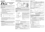
1.1 Outline of Product . . . . . . . . . . . . . . . . . . . . . . . . . . . . . . . . . . . . . . . . . . . . . . . . . . . . . . .
2 .SPECIFICATIONS . . . . . . . . . . . . . . . . . . . . . . . . . . . . . . . . . . . . . . . . . . . . . . . . . . . . . . . . . .
2.1 Appearance and Nameof Each Portion. . . . . . . . . . . . . . . . . . . . . . . . . . . . . . . . . . . . . . .
2.2 General Specifications and Performance Specifications. . . . . . . . . . . . . . . . . . . . . . . . . .
3 .CONNECTIONAND WIRING . . . . . . . . . . . . . . . . . . . . . . . . . . . . . . . . . . . . . . . . . . . . . . . . .
3.1 Connection with the PC . . . . . . . . . . . . . . . . . . . . . . . . . . . . . . . . . . . . . . . . . . . . . . . . . . .
3.2 Power Supply Wiring . . . . . . . . . . . . . . . . . . . . . . . . . . . . . . . . . . . . . . . . . . . . . . . . . . . . .
3.3 Wiring of RS-232C Equipment . . . . . . . . . . . . . . . . . . . . . . . . . . . . . . . . . . . . . . . . . . . . .
4.ALLOCATlON OF BUFFER MEMORIES (BFMs) . . . . . . . . . . . . . . . . . . . . . . . . . . . . . . . . . .
4.1BFMList . . . . . . . . . . . . . . . . . . . . . . . . . . . . . . . . . . . . . . . . . . . . . . . . . . . . . . . . . . . . . . .
4.2 Details of Buffer Memories . . . . . . . . . . . . . . . . . . . . . . . . . . . . . . . . . . . . . . . . . . . . . . . .
5.TRANSMlSSlON PROGRAM . . . . . . . . . . . . . . . . . . . . . . . . . . . . . . . . . . . . . . . . . . . . . . . . .
5.1 Example of sendingheceiving the data of 16-bit buffer length . . . . . . . . . . . . . . . . . . . . .
5.2 Example of sendingheceiving the dataof 8-bit buffer length . . . . . . . . . . . . . . . . . . . . . . .
6.APPENDIX. . . . . . . . . . . . . . . . . . . . . . . . . . . . . . . . . . . . . . . . . . . . . . . . . . . . . . . . . . . . . . . .
.
AMITSUBJSHI
.
iv
1-1
1-1
2-1
2-1
2-2
3-1
3-1
3-2
3-3
4-1
4-1
4-3
5-1
5-1
5-8
6-1
FX2N-232lF RS-232C INTERFACE BLOCK
1.
INTRODUCTION 1
INTRODUCTION
The RS-232C interface block FXZN
-2321F (hereinafter referred to as “2321F) is connected to the FXZN programmable controller
to realize full duplex serial
data communication with another RS-232C
interface such asa personal computer, bar code reader,
printer, etc.
1.1
Outline of Product
Applicable PC
The 2321F can be connected asa special block of the F X ~ N
programmable controller.
Control instructions
Sendheceive datais received andsent and diversified control commands are manipulated using theFROMRO instruction.
Number of VO points
Connection method
The number of I10 points occupied is 8 in all (either input or output). However, the capacity of the 5 V power supplied from
the PC is limited.
The current consumption of the 5 V power of the 2321F is 40 mA. Make sure that the total current consumption of the 5 V
power including other special blocksis equivalent to or less than that available.
Communication method
Full duplex starl-stop synchronization andnon-protocol procedure areused. The communication formatcan be specifiedusing
the buffer memories (BFMs).
Sendreceive buffer
The sendreceive buffer can accommodate 512 bytes1256 words.
When the RS-232C interlink connection modeis used, data exceeding 512 byled256 words can also be received.
hiTSUBISHI
1-1
,
.
FX2N-2321F
BLOCK
INTERFACE
RS-232C
INTRODUCTION 1
ASCIVHEX conversion function
The function to convert and send a hexadecimal numeric (0 to F) saved in the send data buffer as well as the function to
convert a received ASCII code into a hexadecimal numeric(0 to F) and save itto the receive buffer are provided.
RS-232C
FXZN-232IF
INTERFACE BLOCK
SPECIFICATIONS 2
~~
2.
SPECIFICATIONS
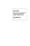
2.1
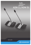
AppearanceandName
of EachPortion
Weight : Approx. 0.3 kgAccessory
: Specialblock No. label
kE
,I
Terminalscrews M3(0.12)
-i
W3.35)
External 24 VDC
round terminal
Y
Dimensions : mm (inches)
[ Front
face
POWER LED
SD (TXD) LED
RD (RXD) LED
ofcover
top
J
[ Side ]
[ Inside of cover
top
]
: Lt when both the 5 VDC power supplied from the PC basic unit and the 24 VDC power supplied from the
external terminal are supplied.
: Lt while data is sent to the RS-232C equipment connected to the 2321F.
: Ltwhile data is received from the RS-232C equipment connected to the 2321F.
FX2N-2321F
INTERFACE
RS-232C
2.2
BLOCK
SPECIFICATlONS 2
GeneralSpecificationsandPerformanceSpecifications
General specifications
Insulating withstand voltage: 500VAC, 1 minute betweenthe entire external terminal andthe ground terminal
Other specifications are equivalent
to those of the PC basic unit.
Performance specifications
24 VDC i1 O%, 80 mA
Driving power supply
Current consumption
5 VDC, 40 mA (supplied from PC via extension cable)
Transmission standard
In accordance with RS-232C, D-Sub 9-pin connector
isolation method
Photocoupler isolation
Transrnlssion distance
15 rn or less
1
2
3
Arrangement of D-sub 9-pin
connector
Operation of each
signal
speed
6
7
8
I
. .
1 POWER, SD (TXD),
(RXD)
RD
indication (LED)
lCommunication
4
method
/Transmission
Full duplex start-stop synchronization, non-protocol procedure. Communication format is
/specifiedby
buffer
memories
(BFMs).
1300,600, 1200,2400,4800,9600,19200
Number of VO points occupied 8 PC I/O points total (either inputor output)
Applicable PC
Communication with PC
h
___h I T S U B I S H I
FXZNprogrammable controller
Communication is performed by FROM/TO instruction given by PC via buffer memories. Each of
sendreceive
accommodates
words.
buffer
256
.-4
2-2
!I
FXZN-232IF RS-232C INTERFACE BLOCK
CONNECTION AND WIRING 3
~
3.
CONNECTION
AND
3.1
ConnectionwiththePC
~~~
WIRING
Connecting the extension cable
The 2321F can be directly connected to the basic unit of the FX~N
PC or connected on the right side of another extension
blockhnit. A number is assigned to each special unit/block counting from the one nearest the basic unit in the way of "No. 0,
No. 1 . . . No. 7". Up to eight special unitdblocks in all can be connected in principle. However, the capacity of the 5 VDC
power supplied from the PC is limited. The current consumption of the 5 VDC power in the 2321F is 40 mA. Make sure that
the total current consumption of the 5 VDC power supply including other special blocks is equivalent to or less than that
available.
FXZN-48MR-ES/UL
XOOO-X027
block
YOOO-YO27
FX2N-2321F
Special
FXPN-16EXFX2N-2321F
-ES/UL Special block
XO30-X047
INo.l/
FX2N-2321F RS-232C INTERFACE BLOCK
3.2
CONNECTION AND WIRING 3
Power Supply Wiring
1
Solid grounding
(100Qorless)
Service power
supply for sensor
I+ I
ov
FXPN PC
-
124~1
*-
24+
~
Extension
cable
24-
FBN-2321F
J-
24V DC*lO%
80mA
24VDC service power
supply of PC may be used.
Wiring
(0.24)
Handling of the crimp-style terminal
Use the crimp-style terminals of the dimensions shown on the figure on the left.
Make sure that the tightening torque of the terminal is 0.5 to 0.8 N (5 to 8 kgfwn).
Tighten each terminal securely to avoid malfunction.
6(0.24)
. 2 m m B € +
AMITSUBISHI
3-2
FX2N-2321F RS-232C
INTERFACE
BLOCK
3.3
CONNECTION
WIRING
AND
3
Wiring of RS-232C Equipment
Pin arrangementof communication connector
#4-40UNC
h screw t h r a
hITSUBISHl
3-3
FX2N-2321F RS-232C INTERFACE BLOCK
CONNECTION
WIRING
AND
3
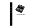
Connectlon example
The signal wiring of the RS-232Cequipmentvanesdepending
on the RS-232Cspecificationsconnected.Check
the
specifications of the RS-232C equipment used,then connect the signals correctly. Representative wiring examples are shown
below.
Connection with counterpart equipment
of terminal specifications (when control line is not used)
BFM 10 communication format: b9= 0, b8 = 0, without control llne
F
IX-2321Fl
@x
Counter part equipment
0SD(TXD)
0RD(RXD)
SD(TXD) @
RD(RXD)
SG
ground)
(signal
Communicationperformed
is
accordance
in
with
the
condition determinedby the software in the 2321F and
the counterpart
equipment.
0 SG
@
(signal ground)
Connection with counterpart equipment
of terminal specifications (when control line
Is used)
Cross cable used,BFM #O communication format: b9= 0, MI = 1, standard RS-232C mode
SD(TXD) @
RD(RXD) @
z:;g
-8
CD(DCD) @ ”
ER(DTR) @
DR(DsR)
SG
@
=o
I
part
equipment
:;E)
0
RS(RTS)
0CS(CTS)
0CD(DCD)
0ER(DTR)
DR(DSR)
0 SG
I
Because the carrier to send
(CS)
signal
pin of the
2321F itself receivesthe request to send (RS) signal,
signal transfer is performed
as
if
the counterpart
equipment is functioning.
*1 When the CD signal is not monitored, the CD
signal pin is not required to be connected. With
regard to the CD signal, the 2321F only indicates
the status.
’2 The 2321F only indicates the status.
.
FX2N-2321F RS-232C
INTERFACE
CONNECTION
WIRING
AND
BLOCK
3
Interlink serial cross cableused, BFM #O communication format: b9 = 1, b8 = 1, RS-232C interlink connection mode
Counter part equipment
SD(TXD) @
RD(RXD) @
RS(RTS) @
CS(CTS) @
0SD(TXD)
-0
ER(DTR) @
SG
@
AMITSUBISHI
RD(RXD)
RS(RTS)
CS(CTS)
0
ER(DTR)
0 SG
In the interlink connection mode, data exceeding
512 bytes (upper limit of the receive buffer in the
2321F) can be received.
*1 The 2321F only indicates the status.
‘2 In this mode, the request to send (RS) signal
functions as the signal to enable receive in the
232 IF.
When receivingdataexceeding
512 bytes
(upper limit of the receive buffer in the 2321F),
the 2321F sets the request to send (RS) signal
to “OFF” andrequeststhecounterpart
equipment to suspend the send operation.
When the data saved in the receive buffers is
read by the sequence program, the remaining
data can be received.
3-5
FXZN-2321F RS-232C
INTERFACE
BLOCK
CONNECTION
WIRING
AND
3
Connection wlth counterpart equlpment of modem specificatlons (Control line is essential.)
Straight cable used,BFM #O communication format: b9= 0, b8 = 1, standard RS-232C mode
Counter part equipment
'1 The 2321F indicates the status exclusively.
SD(TXD) @
SD(TXD)
'2 When the CD signalis not monitored, the CD
signal pin is not required to be connected.
RD(RXD) @
RD(RXD)
Withregard to the CD signal, the 2321F
RS(RTS) @
RS(RTS)
indicates the status exclusively.
CS(CTS)
'3 When the CI signal is not required, the CI
CS(CTS) @
signal pin is not required to be connected.
CD(DCD) @ **
, *7 OCD(DCD)
With regard to the CI signal, the 2321F
ER(DTR)
ER(DTR) @
indicates the status exclusively.
-0
___f__
.
. *'
__f___
DR(DSR) @ "
___f__
SG
CI(RI)
@
@ '3
,
.
,
0
0
0
0DR(DSR)
0
0 SG
*3 OCI(RI)
n
FX2N-2321F RS-232CINTERFACE BLOCK
ASSIGNMENT OF BUFFERMEMORIES (BFMs) 4
ALLOCATION OF BUFFER MEMORIES (BFMs)
BFM List
4.
4.1
The RS-232C interface block F&~-2321F (2321F) transmits data with the PC via the buffer memories BFMs (16-bit RAM
memories) in the 2321F.
FNC78 (FROM) and FNC79 (TO) instructions are used to read and write the buffer memories.
!ad
BFM
No.
I 0087H
# o /Communication format
--.....
Name
Qaitinnranna
I
1
I
1
# 3 Receive time-out time
1
,
,
1 to 512 (when data length is 16 bits)
1 to 256 (when data length is 8 bits)
"0"
as "512" or "256".
- is
__ treated -j
10 ms)
,,me-out time.
# 4 ISend header, lower
bytes2
Id hwtne maw
Tero suppression
L
# 5 jSend header, upper 2 bytes
# 6 Send terminator, lower 2 bytes
14 bytes max., zero suppression
# 7 Send terminator, upper 2 bytes
# 8 Receive header, lower 2 bytes
I4 bytes max., zero suppression
# 9 Receive header, upper 2 bytes
# 10 Receive terminator, lower 2 bytes
4 bytes max., zero suppression
# 11 Receive terminator, upper 2bytes
# 12 Receive SusDension waitinatime (in interlink connection) 0 to 32.327 (X 10 msl
, ~ Y , . Y Y I I I U , . . ,
I # 13 1 Number of remaining send data
# 14 Number of receive buffers
# 15 Send sum result
# 16 Receive sum result
AMITSUEUSHI
11.1
-1
# 1 Command
# 2 Receive upper limit byte count
". valnle IE,I wlf!r-r!x o r write
I ......
InHial
u
IU d l C ~""P"
0 to 256 (when data length is 8 bits)
Oto256+ 15 '1
W
W
~
4
0
W
I
0
W
!
(no header)
terminator)
0
(no header)
0
0
0
W
W
1
I
W
w i
W
I
R
R
R
8
U
0
0
0
4-1
,
-
FXZN-2321F RS-232C INTERFACE BLOCK
BFM
Name
No.
# 20 Time from CS ON to send start
# 21 Time from completion of actual sendto RS OFF
(completion flag ON)
# 28 Status
# 29 Error code
# 30 Model code
#loo0 Send byte count
#loo1
t o Send buffers
ASSIGNMENT OF BUFFERMEMORIES (BFMs) 4
rangeSetting
0 to 32,327 (X 10 ms)
0 to 32,327 (X 10 ms)
Initial value ~
0
Oto512+30 ‘1
0 to 256 + 15 *1
W
w
0
0
K7030
R
R
R
W
0
w
0
R
#2000
0
to Receive buffers
#2256
#2257
0
to Spare receive buffers forinterlink connection mode
#2271
Note: “W: For write” canbe used for read also. Undefined BFM Nos. are not allowed to be used in the program.
‘1 : Spare buffers used in the interlink connection mode
~~
j
~
0
0 to 512 (when data lengthis 16 bits)
0 to 256 (when data lengthis 8 bits)
#1256
#2WO Receive byte count
1
R
R
I
~
.
ASSIGNMENT OF BUFFER MEMORIES (BFMs) 4
FXZN-232IF RS-232CINTERFACEBLOCK
4.2
Details of Buffer
Memories
BFM #O:Communication format
Bit
bO
Description
Data length
F
l Parity
b3
I
Stop bit
b4
Baud rate (bps)
b7
k:
~
Control line
0
7 bit
initial
1 : 8 bit
18 bit
(00): None
(01) :Odd
(11) : Even
1 bit
12 bit
I(OOl1) : 300
(0100) : 600
(0101) : 1200
(0110) : 2400
(0111) : 4800
(1000): 9600
(I
001 j : 19200
(00) : Not used
(01) : Standard RS-232C
(11) : RS-232C interlink connection mode
i
blO Addition of CR and
b l l ILF
value
1
(11) : Even
0 : 1 bit
(1000) : 9600 bps
(00) : Not used
(00) : Not added
~~~~~
(11) : CR and LF
(00) : Not availablc
~
1
data
lenath
-.
...
..
- ..
I
I-.
b15 Undefined (disabled)
AMITSUBISHI
I
8 bit
I
0 : 16 bit
IO: Undefined
4-3
ASSIGNMENT OF BUFFERMEMORIES (BFMs) 4
FX2N-232/FRS-232ClNTERFACEBLOCK
The communication format is determined on
the rising edge of the sendreceive enable command (BFM #1 bo).
Accordingly, the setting of the communication format shouldbe preliminary transferred using theTO instruction before BFM
#1 bO is turned on. Also, the send header and the send terminator are determined
in the rising edge of the send command
are determined on the rising edge of BFM #I
bO or on the rising
(BFM #1 bl). The receive header and the receive terminator
#1 b2). Accordingly, when onlythe header andthe terminator exclusively
edge of the receive completion reset command (BFM
are changed it is not necessary to turn BFM #1 bO off. The change becomesvalid from the next sendreceive operation.
Setting example of communication format
(hexadecimal, constant specification)
bit
Data length : 8 bits
Parity : Odd
Stop
: 1 bit
Baud rate : 2,400bps
~
~
b12
b15
1
~
~
4
~
bll
1
/
b8b7
~
0
1
(4063H)
~
b3 b4
~
6
Control line : Not used
CR, LF : Not added
ASClllHEX
and
Check
sum
conversion
Buffer data length : 8 bits
h
AMITSUBISHI
KO
available
: Not
pulse
KO
~
H4063
o
1
1
bO
3
K1
----
Block No. BFM
Set Number
of
valuetransferpoints
h
4-4
~
l
o
~
o
/
FX2N-2321F RS-232CINTERFACEBLOCK
ASSIGNMENTOFBUFFER
MEMORIES (BFMs) 4
Select the communication format used to sendreceive data in
the 2321F among 9 types shown on the left.
The header can be specified in the
communication format.
.... .... ......
;.... .....,...
~
portion in the
hexadecimaldata (binary)
In the communication formattype 0,
and ASCII code can be send and received.
In the communication format types Q to @,the sendreceive
data should be any ASCII code except the header, the
terminator, CR and LF.
Communication can be performed using the ASCIVHEX
conversion function by specifying
the BFM #O b13 and the BFM
#O b12.
The ASCII codesavailable for the initial terminator are 01H to
1FH.
In the RS-232Cinterlink connection mode,the communication
formats Q to 8 are available.
AMITSUBISHI
4-5
FXZN-2321F RS-232CINTERFACEBLOCK
ASSIGNMENTOFBUFFERMEMORIES
(BFMs) 4
0 bO to b7 (data length, parity, stopbit and baud rate):
the communication specificationsof the connected counterpart equipment.
bO to b7 should be aligned with
0 b9 and b8 (controlline):
For examplesof connecting the equipment correspondingto each setting, referto Paragraph 3.3.
0
0
0
When not used (b9 = 0, b8 = 0) is specified, communication is performed using only the SD and RD signals without
using thecontrol line.
When standard RS-232C mode (b9 = 0, b8 = 1) is specified, a cross cable is required to connect the equipment of
terminal specifications anda straight through cableis required to connect the equipmentof modem specifications.
When RS-232C interlink connection mode (b9 = 1, b8 = 1) is specified, the request to send (RS) signal functions as
byte count (BFM#2),
the signal to enable receivein the 2321F. When receiving data exceeding the receive upper limit
the 2321F sets the request to send (RS) signal to OFF and requests the counterpart equipment to suspend the send
operation.
At this time, when the data saved
in the receive buffersis read to data registersin the PC using the sequence program,
the remaining data can be received.
Make sure to perform the RS-232Cinterlink connection when specifying this mode.
0 b l l and b 10 (additionof CR and LF):
Set these bits as follows.
0
added
Not
CRonlyisadded.
( b l l =0, b10=0)
( b l l = 0, b10 = 1)
CRandLFareadded. ( b l=l 1 , b 1 0 = 1 )
For the CR/LF addition format, refer
to the communication format list shown above.
0
h
AMITSUBISHI
.. .
LI
- ..
4-6
FX2N-232IF RS-232C INTERFACEBLOCK
ASSIGNMENT OF BUFFERMEMORIES (BFMs) 4
0 b13 and b12 (Availability of check sum and ASCIVHEX conversion):
Set these bits as follows.
= 0, b12 = 0)
0
Neither the check sum nor the ASCWHEXconversion is available.(b13
0
The ASCIVHEX conversion only is available.
(b13 = 0, b12 = 1)
0
The check sum only is available.
(bl3=1,b12=0)
Both the check sum and the ASCIVHEXconversionareavailable.
(b13 = 1, b12 = 1)
For the check sum addition format, refer to the communication format list shown above.
0
hITSUBISHl
4-7
ASSIGNMENT OF BUFFERMEMORIES (BFMs) 4
FX2N-2321F RS-232C 1NTERFACE BLOCK
When execution of the ASCIVHEX conversion is specified, the hexadecimal numeric data (0 to F) inside the send buffers
(BFMs #lo01 to #1256) is converted intothe ASCII code, then sent. The received ASCII codeis converted into hexadecimal
numeric data (0 to F), then saved to the receive buffers (BFMs #2001to #2256).
At this time, the sendheceive byte count indicates the numberof hexadecimal data.
Send format when hexadecimal data is converted into ASCII code
Example: Whenthe send data“~OABH”,the header “STX” and the terminator “ E W are sent
Send data buffer BFM #lo01
b15
bO
~~~#010j0l0j11o1o(o]oI11o111o111o11(11
I
1
I
O
I
A
I
B
l
=3
Converted intoASCII code
before send
m
i
2
1
2H31
3H
3Oii
The send byte count is “4“.
Receive format when ASCII code Is converted Into hexadecimal data
Example: Whenthe receive data “~OABH”,
the header “STX” and the terminator“ E W are received
b15
bO
o ~ o ~ o ( 1 ~ o ~ o ~ o ~ o
Receive data buffer
BFM #I2001 byte
1
--.-
<
byte
1
1
0
.
, *
,.
I
1
The receive byte count is “2“.
e
B
1 ~ 0 ~ 1 ~ 0 (
FX2N-2321F RS-232C INTERFACE BLOCK
ASSIGNMENT OFBUFFER MEMORIES (BFMs) 4
0 b14 (sendreceive buffer data length):
The data is treated as follows in accordance with the buffer data length.
In the case of 16 bits (b14 = 0)
Sendlreceive buffer
I S ~BFM IBFM
IBFM
16-bit data is divided into
upper 8 bits and lower 8 bits,
then sent and received.
1~1
ExarnDle of send buffers
T #lo01 #loa1 #lo02
X lower upper lower
/BFM
#lo02 T
upper
In the case of 8 bits (b14 = 1)
Sendreceive buffer
I S ~BFM IBIFBMFM
Upper 8 bits are ignored,and
lower 8 bits only are sent
and received as valid data.
ExamDle of send buffers
T #lo01 #lo02 #lo03
X lower lower lower
hITSUBISHl
/BFM
#lo04
lower
1l;
T
4-9
ASSIGNMENT OF BUFFERMEMORIES (BFMs) 4
FX2N-2321F RS-232C INTERFACE BLOCK
BFM #l:
Command
I
I
1
I
bO
I
Description
1 Sendreceive enable
(ER
ON)
bl
ISend command
Bit
b2
b3
I Receive completionresetcommand
I
I
I
I
Error reset
BFM #1 gives the command for sendreceive and the status information reset command to the 2321F.
0 bO (sendheceive enable):
While bO is turned on, the 2321F can send and receive data.
The contents of the following setting items are determined on the rising edge of bo. Make sure to set the contents using
the TO instruction before setting bO to "ON".
0
BFM#O
(communication format)
BFMs #9 and #8
(receive
header)
BFMs #11 and #10
(receive
terminator)
On the rising edge of bo, the error occurrence (BFM #28 b3)and the error code (BFM #29) are cleared.
0 b l (send command):
On the rising edge ofb l , the contents of the send buffers (BFMs #lo01 to #1256) are sent to the counterpart equipmentup
to the send byte count (BFM #lorn).
When send is completed, the send completion status (BFM #28 bo) is set. BFM #28 b0 is automatically reset when the
next send command (bl) is given.
When b l is given, the contents of the following setting items are determined.
BFMs #5 and #4
BFMs #7 and #6
(send header)
(send terminator)
A
AMITSUBISHI
4-1 0
ASSIGNMENT OF BUFFER MEMORIES (BFMs) 4
FXZN-2321F RS-232CINTERFACEBLOCK
0 b2 (receive completion reset command):
When b2 is set to “ON”, the following items are cleared.
0
BFM#28 b l
0
#2000
BFM
(receive
byte
0
BFM#2001 to #2256
(receive completion)
count)
(receivebuffers)
When receive is completed, b2 should be set to “ON” to clear the receive completion status (BFM #28 bl). If BFM #28 b l
is not reset, the next data cannot be received.
When b2 is set to “ON”, the contents of the following setting items are determined.
0
BFMs #9 and #8
0
BFMs #11 and # l o
(receive header)
(receive terminator)
In the RS-232C interlink connection mode (BFM #O b9 = 1, b 8 = l ) , b2 functions as the receive continuation command to
receive data exceeding the receive upper limit byte count (BFM #2), and clears the following items.
0
#28
BFM
0
BFM #2000
0
BFMs#2001 to #2256 (receive buffers)
b4
(receive
suspended)
(receive
byte
count)
0
BFMs #2257 to #2271 (sparereceive buffers)
When b2 is set to “ON”, the request to send (RS) signal is automatically set to “ON” also.
0 b3 (error reset):
When b3 is set to “ON”, the error occurrence status (BFM #28 b3) and error code (BFM #29) are cleared.
AMITSUBISHI
4-1 1
FX2N-2321F RS-232CINTERFACEBLOCK
ASSIGNMENT OF BUFFERMEMORIES (BFMs) 4
BFM #2: Receive upper limit byte count
Setting range 1 to 512 (when buffer data length is 16 bits)
1 to 256 (when buffer data length is 8 bits)
"0"is regarded as "512" or"256. The initial value is "0".
BFM #2 specifies the maximum byte countreceived by the 2321F.
When data is received up to the receive upperlimit byte count, the receive completion status (BFM #28 b l ) is set.
When the receive terminator (BFMs #11
and #lo) or the receive time-out time (BFM #3) is set and the set condition is satisfied,
it is regarded that receive is completed even if the data received is within the receive upper limit byte count.
BFM #3:Receive time-out time
Setting range 1 to 32,767 (x 10 ms)
" 0eliminates time-out time. The initial value is "0".
BFM #3 specifies the receive data waiting time limit.
When the next data is not received within the receive time-out time starting from the receive edge of each data, the receive
time-out flag (BFM #28 b2) is set to "ON", it is regarded that receive is completed, and the receive completion status (BFM
#28 b l ) is set.
AMITSUBISHI
... -.
4-12
FX2N-232IF RS-232C INTERFACE BLOCK
ASSIGNMENT OF BUFFER MEMORIES (BFMs) 4
BFMs #5 (upper) and #4 (lower): Send header
Setting range 4 bytes maximum, zero suppression
The initial value is "0" (not provided).
For the send data ofthe 2321F, 4 headers maximum can be specified. When the number of headers
is less than4, the upper
"0"sare ignored (zero suppression) and not transferred.
i;ilgBFM #5(upper 2 bytes) 7
7
BFM #4(lower 2 bytes)
bO b15
bO
~ o ~ o / o ~ o ~ o ~ o [ o ~ o ~ o~0/0~0~0~0~0~0~0~0~0~0~0~0~0~1j0~
~o~o~o~o~o~o~o~
i
o
4th
1
~
1
~
l
l
L
3rd -J 1st2nd
~
1
l
~
1
~
1
~
1
~
1
Example:02H(STX)
0
The transmission order is fourth header, third header, second header, first header when 4 headers are specified.
BFMs #7 (upper) and#6 (lower): Send terminator
Setting range 4 bytes maximum, zero suppression
The initial value is "0"(not provided).
For the send dataof the 2321F, 4 terminators maximum can be specified. Whenthe number of terminators is less than 4, the
upper "0"sare ignored (zero suppression) and not transferred.
As the first terminator, specify an ASCII code from 01H to 1FH. (As the secondto fourth terminators, any ASCII code can be
specified.)
The register structure andthe transmission order are equivalentto those of thesend header described above.
hlTSUWSHl
4-1 3
FX2N-2321F RS-232CINTERFACEBLOCK
ASSIGNMENT OF BUFFERMEMORIES (BFMs) 4
BFMs #9 (upper) and#8 (lower): Receive header
Setting range 4 bytes maximum, zero suppression
The initial value is "0"(not provided).
For the receive data of the 2321F, 4 headers maximum can be specified. When the number of headers is less than 4, the
upper "Os are ignored (zero suppression).
The register structure and the transmission order are equivalent to those of the send header described above.
BFMs #11 (upper) and#lo (lower): Receive terminator
Setting range
4 bytes maximum, zero suppression
The initial value is "0" (not provided).
For the receive data of the 2321F, 4 terminators maximum can be specified. When the number of terminators is less than 4,
the upper "0"sare ignored (zero suppression).
As the first terminator, specifyan ASCII code from 0 1 to~1FH. (As the second to fourth terminators, any ASCII code can be
specified.)
The register structure and thetransmission order are equivalent to those of the send header described above.
FX2N-2321F RS-232C INTERFACE BLOCK
ASSIGNMENT OF BUFFER MEMORIES (BFMs) 4
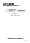
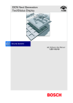
BFM #12: Receive suspension waiting time
Setting range 0 to 32, 767 (x 10 ms)
The initial value is 0 ms.
In the RS-232C interlink connection mode (BFM #0,b9 = 1, b8 = l ) , when receiving data exceeding the receive upper limit
byte count (BFM #2), the 2321F sets the request to send (RS) signal to "OFF" and requests the counterpart equipment to
suspend the send operation.
BFM #12 specifiesthe time after the requestto send (RS) signalis turned off until the receive suspended status (BFM
#28 b4)
is turned on. The value set to the BFM #12 should be equivalentto or more thanthe time after the 2321F sets the requestto
send (RS) signal to "OFF" until the send operationof the counterpart equipmentis completely suspended.
If the time times out and the receive suspended status (BFM
#28 b4) is set to "ON" before the send operationof the counterpart
equipment is not suspended, the remaining data cannot be received.
(BFM#2257to #2271)
Receivebyte
count
BFM#2000
,----K
ReceiveupperSet
to thetime
limitbytecountthesendoperation
@----I
1
:
'
R W J a t toseM{RS) ,,
(BFMM)
Data
receive
is
suspended.
Receive suspended
BFM#28 b4
in which
of
the counterpart
equipment is
completely suspended.
/
II
<
Suspension waiting time(BFM#12)
0 to 32,767(xlOms)
AMITSUBISHI
4-15
FX2N-2321F RS-232CINTERFACEBLOCK
ASSIGNMENT OF BUFFERMEMORIES (BFMs) 4
BFM #13: Number of remaining send data
Saved value 0 to 51 2 (when buffer data length is 16 bits)
0 to 256 (when buffer data lengthis 8 bits)
The send byte count (BFM #low)reduced bythe number of data actually sent is during transmission.
BFM #14: Number of receive buffers
Saved
256+15
receive
spare
(for
buffers)
The number of buffers which have actually received data is saved in turn with regard to the receive buffers BFM #2001 to
#2256 andthe spare receive buffersBFM #2257 to #2271 for interlink connectionmode.
rcL
AMITSUBISHI
h
4-1 6
FXZN-232IFRS-232CINTERFACEBLOCK
ASSIGNMENT OF BUFFER MEMORIES (BFMs) 4
BFM #15: Send sum result
0
Initial value
The check sum value addedto the send data is saved.
The sum check target rangeand the calculation method are shown below.
-
Sum check target range and calculation method
Example:
Header
Terminator
Check
sum
h
E
T
X
T O A 1 2 5 F X 5 2
S
02H30H41H31H32H35H46H03H35H32H
it
3OH+41
Target range
H+31
H+32H+35H+
The total value includingthe terminator and excludingthe header (1st byteof the header only)is calculated. Then, the lower
1 byte is converted intothe ASCII code, and sentor received. The data converted into the ASCII code
is placed in the order
of upper digit and lower digit.
FX2N-232iF RS-232C iNTERFACE BLOCK
ASSIGNMENT OF BUFFERMEMORIES (BFMs) 4
BFM #16:Receive sum result
Initial value:
0
The sum checkvalue of the receive data is saved.
When the check sum addedto the receive data is different fromthe receive sum result, "receive sum check error" occurs.
The sum checktarget range andthe calculation methodare equivalent to those for the send sum result described above.
BFM #20:Time from CS ON to send start
Set value
0 to 32,767 (x 10 ms)
The initial value is 0 ms.
The time after the clear to send (CS) signal is turned on until the 2321F starts the send operation canbe set.
When "control line not used" is specified, the time after the send command is given until the send operation is started is
specified.
Set BFM #20 when it is required by a modem, etc.
BFM #21: Time from completion of actual send
to RS OFF (completion flag ON)
Set value
0 to 32, 767 (x 10 ms)
The initial value is 0 ms.
The time after the 2321F sends the data until the RS signal is turned off and the send completion flag (BFM#28 bo) is turned
on can be specified.
Set BFM #21 when it is required by a modem, etc.
AMITSUBISHI
4-1 a
FXZN-2321F RS-232C INTERFACE BLOCK
1
1
1
1
1
1
BFM #28: Status
Bit
bO
1 Description
I Send
completion
b4
I Receivesuspended
b5
IUndefined
b6
IBeing sent
b7
1 Being received
I
I
I
I
I
I
ASSIGNMENT OF BUFFER MEMORIES (BFMs) 4
Bit
Description
b8
RS (RTS)
b9
b10
ER (DTR)
Undefined
bll
Undefined
b12
-DR (DSR)
b13
CD (DCD)
b14
DS (CTS)
b15
CI (RI)
j
The 2321F status and the sendreceive result aresaved as status information. This information can be read from the PC using
the FROM instruction. then utilized.
0 bO (send completion)
When send of data up to the send byte count (BFM # l o w ) is completed, the send completion status (bo) is set. The send
completion status (bo) is automatically reset when the next send command (BFM #1 b l ) is set to "ON".
0 b l (receive completion)
When receive ofdata up to the receive upper limit byte count (BFM #2) is completed, the receive completion status (bl) is set.
If the receive terminator (BFMs
#11 and #lo) or the receive time-out time (BFM #3) is set, it is regardedthat receive is completed
when the set condition is satisfied, then the receive completion status (bl) is set in the same way.
This status isrequired to be reset using the sequence program. If it is not reset, the next data cannot be received. This status
can be reset using the receive completion reset command (BFM #1 b2).
AMITSUBISHI
4-1 9
FX2N-2321F RS-232CINTERFACEBLOCK
ASSIGNMENT OF BUFFERMEMORIES (BFMs) 4
0 b2 (receive time-out)
When the receive time-out time (BFM #3)is reached while data is received, the receive time-out status (b2)is set. At the
same time,the receive completion status(bl) is also set.
This status is automatically reset when the receive completion resetcommand (BFM #1 b2)is executed.
0 b3 (error occurrence)
When an error occurs while data is sent or received,
b3 is set to “ON” and the error is saved to the error code (BFM#29).
0 b4 (receive suspended)
When data exceeding the receive upper limit byte count (BFM #2) is received in the RS-232C interlink connection mode
the 2321F sets the request to send (RS) signal to “OFF“, requests the counterpart equipmentto
(BFM #O b9 = 1, b8 = l),
suspend the send operation, then sets b4 after the receive suspension waiting
time (BFM #12) has expired.
To receive the excess data in the interlink connection,
the rising edge of the b4 isrequired to be monitored usingthe sequence
program. The data as much as the receive byte count (BFM #2000)in the receive buffers (BFMs #2001to #2271) or the
data as much as the number of receive buffers (BFM #14) should be read to data registers in the PC and the receive
completion command executed (BFM #1 b2).
0 b6 (being sent)
b6 is turned on after the send command (BFM#1 b l ) is given until the send completion status (BFM #28bo) is set.
0 b7 (being received)
b7 is turned on after the head data is receiveduntil the receive completion status(BFM #28 b l ) is set.
(RS),b9 (ER),b12 (DR), b13 (CD), b14 (CS), b15(CI)
These bits indicatethe ONlOFF status of the control signals.
0 b8
AMITSUBISHI
4-20
FX2N-2321F RS-232C INTERFACE BLOCK
ASSIGNMENT OF BUFFER MEMORIES (BFMs) 4
BFM #29: Error code
I Code I
I1
0
INo error
Description
I
Receive parity error, OVeRZlnerror, framing
1
1
1
~
2
3
4
tundefined
1 Defectivecharacter
receive
I Receive sum check error
Receive buffer overflow (only ininterlink
connection mode)
I Baud rate setting error
I
6
1
-
I
1
I
Communication format such as baud rate is not matched.
Control timing is not matched.
I
1 Receive data is not ASCII code.
1 Receive sum is not equal calculated sum
result
(BFM
#16).
Receive byte count exceeds 512 +30 bytes.
Decrease receive upper byte count (BFM #2), and increase
spare receive buffer area.
I
1 Non-existing baud rate is specified.
1
placed in correct position.
7
Receive CR error
8
Receive LF error
LF is not placed in correct position.
Sendheceive initial terminator setting error
Initial terminator is other than 01H to 1FH.
Receive terminator error
Receive terminator is not placed in correct position or not
matched.
9
1
Causes and countermeasures
10
11
12
IUndefined
Transmission sequence
error
1
AMITSUBISHI
not is CR
-
ITransmission sequence is not matched.
4-2 1
I
I
I
ASSIGNMENT OF BUFFERMEMORIES (BFMs) 4
FX2N-2321F RS-232CINTERFACEBLOCK
BFM #30: Model code
The model codeof the 2321F is "K7030".
The model codeis a fixed code assignedto each special extension equipment handled the
by FROMKO instruction. The PC
can distinguishthe equipment type by reading this code.
BFM #1000: Send byte count
Setting range 0 to 512 (when buffer data length is 16 bits)
0 to 256 (when buffer data length is 8 bits)
The BFM #lo00 specifies how many bytesout of 512 byted256 words in the 16-bit send buffers(BFMs #lo01 to #1256) are
to be sent.
BFMs #lo01 to #1256: Send buffers
Each of them is a 16-bit buffer to save the send data, and accommodates512 bytes1256 words.
Sendlreceive buffer structure
F
bl
Example:#1001(16-bit buffer)
Upper
bits
I
Lower
bits
7
0 ~ 0 ~ 1 ~ 1 ~ 00 ~~ 01 ~~ 10 ~~ 00 ~ 0 ~ 0 ~ 0 ~ 1
3
1
2
4
1
1
41 H=[A]
32H=[2]
d
I
k
1 byte
.,
n
.
1 word
1 byte
>I
>i
A numeric in the sendheceive buffer is treated as hexadecimal (HEX).
FXZN-2321F RS-232CINTERFACEBLOCK
ASSIGNMENT OF BUFFER MEMORIES (BFMs) 4
BFM #2000: Receive byte count
Savedvalue
0 to 51
'I (when buffer data length is 16 bits)
0 to 256+15'I (when buffer data length is 8 bits)
The byte count received from the counterpart equipment is saved.
This value is cleared by the receive completion reset command (BFM #1 b2).
*1 Spare buffers in the interlink connection mode
BFMs #2001 to #2256: Receive buffers
Each of them is a 16-bit buffer to save the data received from the counterpart equipment, and accommodates 512 bytes/256
words. The buffer structure is equivalent to that of the send buffers.
The receive contents arecleared by the receive completion reset command (BFM #1 b2).
BFMs #2257 to #2271: Spare receive buffers for interlink connection mode
Each of them is a spare buffer for the interlink connection in the case where the data exceeding 51 2 bytesis received, and is
used to receive the data after the request to send (RS) signal is turned off until the send operation of the counterpart equipment
is suspended.
The receive contents arecleared by the receive completion reset command (BFM #1 b2).
hITSUBISHl
4-23
FX2N-232IF RS-232CINTERFACEBLOCK
ASSIGNMENT OFBUFFER MEMORIES (BFMs) 4
MEMO
n
.
AMITSUBISHI
~
. .. .~.
4-24
FX2N9321F RS-232C INTERFACE BLOCK
5.
5.1
TRANSMISSION PROGRAM 5
TRANSMISSION PROGRAM
Example of sendingheceivingthedata of 16-bitbufferlength
This paragraph describes an example
in which data of16-bit buffer lengthis sent and received between the equipment of the
terminal specifications. In this example, the ASCII code saved in the data registers D201 to D205 in the PC is sent to the
counterpart equipment, and thedata received fromthe counterpart equipment is saved to thedata registers 0301 to D304 in
the PC.
System configuration
FX2NPC
~MITSUslSHl
l l
FXZN-2321F
5-1
FX2N-2321F RS-232C 1NTERFACE BLOCK
TRANSMISSION
PROGRAM
Setting exampleof buffer memories (The items not described here are set to the initial value respectively.)
BFM #0: Communication format
Bit
Description
bo Data length
1
l~arity
Setting
(1): 8 bits
I(1, 1): Even
(1): 2 bits
Stop bit
b3
(1001): 19200 bps
1
E:1
i
Control line
Addition of CR and LF
Availability of check sum and
ASCIVHEX conversion
bl
1
b8
b15
1
Sendheceive buffer data
length
Undefined
I
I
(0,O):Not used
(0,
0):
Not added
I(0, 0): Not available
(o):
bits
b15
b7
bO
101010101010101011 lo1011 I 1 I 1 I 1 I 1
I
I
i
1
C
Specificationitemfor
16-bit lenath
5
FX2N-2321F RS-232C
INTERFACE
TRANSMISSION PROGRAM 5
BLOCK
BFM #1: Command
MO bo: Sendheceive enable (ER ON)
M1 -t b l : Send command
M2 b2: Receive completion reset command
M3 -t b3: Error reset
-+
+
BFM #2: Receive upper limit byte count
8 bytes
BFMs #4 to #11: Header and terminator
BFMs #4 and #8 (sendreceive header): 02H (STX)
BFMs #6 and # l o (sendheceiveterminator): 03H (ETX)
BFM #28: Status
bO --t M10: Send completion
b l -* M l l : Receive completion
b2 --t M12: Receive time-out
b3 M13: Error occurrence
b4 M14: Receive suspended
b5 M15: Undefined
b6 M16: Being sent
b7 M17: Being received
-+
-+
--t
b8 M18: RS(RTS)
b9 M19: ER(DTR)
b10 M20: Undefined
b l l M21: Undefined
b12 M22: DR(DSR)
b13 -, M23: CD(DCD)
b14 --t M24: CS(CTS)
b15 M25: CI(RI)
-+
--t
-+
--t
+
-t
BFM #1000: Send byte count
9 bytes
AMITSUBISHI
5-3
TRANSMISSION PROGRAM 5
FX2N-2321F RS-232C INTERFACE BLOCK
0FMs #lo01 -: Send buffers
Nine-byte send data"123456789 is prepared in ASCII code in accordance with the send byte count specified above.
Upper byte
2nd byte
[
(BFM#1001)
(BFM#1002)
(BFM#1003)
2 (32H)
I (MH)
4
byte
I 6 (36H)
4th byte
6th
(BFM#1004)
10th byteis not sent.
I
8th byte
8 (38H)
I
I
I
I
Lower byte
lstb e
1 (31H)
3rdb e
3(33H)
I
5th byte
5 (35H)
7th b e
7 (37H)
(BFM#1005)
BFMs #2001 -: Receive buffers
Eight-byte receivedata specified in accordance with the receive upper limitbyte count (BFM #2) is read to the data registers
D301 to D304 in the PC.
AMITSUBISHI
5-4
FXZN-2321F RS-232C lNTERFACE BLOCK
TRANSMISSION PROGRAM 5
Example of sequence program
Transfer of communication format
(OOSFH+BFM#O)
IS
Transfer of receive upper limit byte count
(K 8+BFM#2)
Send header
(02~-1BFM#4)
Send terminator
(03H+BFM#6)
Receive header
(02H+BFM#8)
Receive terminator
(03~+BFM#10)
x000
Seid command input
M1
-----IF
--I
~
-
M1
PLS
FNC 12
MOV
200
Sendcommand
Send bytecount
(K9-1 D200)
FNC l 2 H3837
V
D 204 (
FNC l 2 H0039 D 205 (
MOV
AMITSUBISHI
Unused
I
Send data(as many as9 bytes)
[I 234567891
FNC l 2 H3635 D 203 (
- 9)
5-5
FX2N-2321F RS-232C INTERFACE BLOCK
TRANSMISSIONPROGRAM 5
and send data
-
M8003
monitor
Sendheceive enable
(BFM#28 b15to bO+M25 to M10)
I
IVI I W
-
\
Send completion
Fyin
Error occurrence
FNC78
i
Read of receive buffers
KO K2001
K4
tFM#2002+0302)
D301
BFM#2001jD301
BFM#2003+D303
BFM#2004+D30
Receive completion reset command
Transfer of command
(M3 to MO+BFM#l b3 to bo)
c--
n
FX2N-232IF RS-232C INTERFACE BLOCK
TRANSMISSIONPROGRAM 5
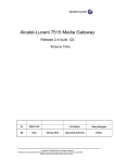
Operation chart
1
Receive
Amrrsumsnl
5-7
BLOCK
FX2N-2321F RS-232C
INTERFACE
5.2
TRANSMISSION
PROGRAM
5
Example of sendingreceiving the data of 8-bit buffer length
This paragraph describes an examplein which dataof 8-bit buffer length is sent and received betweenthe equipment of the
terminal specifications. In this example, the ASCII code saved in the data registers D201 to D209 in the PC is sent to the
counterpart equipment, andthe data received fromthe counterpart equipmentis saved to the data registers0301 to D308 in
the PC.
System configuration
I
FXlNPC
I
1 1
I
1
FXZN-2321F
FX2N-232IF RS-232C INTERFACE BLOCK
TRANSMISSION PROGRAM 5
Setting exampleof buffer memorles (The items not described here are set
to the initial value respectively.)
BFM #O: Communication format
Bit
Description Setting
Data
length
bO
(1): 8 bits
1
1
1
( 1 , 1 ) : Even
I
!
b3
b4
I' Eb7:
~
b12
b13
11 b14
I
b15
1
Stop bit
(1): 2 bits
Baud rate
(1001): 19200 bps
Control line
(0,O):
Not used
Addition of CR and LF
(0,0): Not added
(o, o): Not available
Availability of checksum and
ASCIVHEX conversion
Sendreceive buffer data
length
I Undefined
~
(,):
I
~~~~~
bits
-
I
+ Specification
itemfor
8-bit length
FX2N-232IF
RS-232C
INTERFACE
TRANSMISSION PROGRAM 5
BLOCK
BFM #1: Command
MO bo: SencUreceive enable (ER ON)
M1 b l : Send command
M2 b2: Receive completion reset command
M3 b3: Error reset
--
+
+
BFM #2: Receive upper limit byte count
8 bytes
BFMs #4 to #11: Header and terminator
BFMs #4 and #8 (send/receive header): 02H (STX)
BFMs #6 and # l o (sendheceive terminator): 03H (ETX)
-.
BFM #28: Status
bO M10: Send completion
b l M11: Receive completion
b2 -, M12: Receive time-out
b3 M13: Error occurrence
b4 M I 4: Receive suspended
b5 M15: Undefined
b6 M16: Being sent
b7 M I 7: Being received
+
+
-+
+
-t
+
BFM #1000: Send byte count
9 bytes
--
b8 M18: RS(RTS)
b9 M19: ER(DTR)
b10 M20: Undefined
b l l --t M21: Undefined
b12 M22: DR(DSR)
b13 M23: CD(DCD)
b14 M24: CS(CTS)
b15 M25: CI(RI)
-.
-+
+
FX2N-2321F RS-232C
INTERFACE
TRANSMISSION PROGRAM 5
BLOCK
BFMs #IO01 -: Send buffers
Nine-byte send data“123456789’ is prepared in theASCII code in accordance with the send byte count specified above.
(BFM#1001)
I
(BFM#1002)
I
(BFM#1003)
(BFM#1004)
I
I
Upper
byte
Lower
byte
Ignored
I
1 (30~)
Ignored
I
2 (311-1)
Ignored
I
3 (32~)
Ignored
I
4 (33~)
2b e
3 b te
4b e
(BFM#1005)
(BFM#1006)
(BFM#1007)
(BFM#1008)
(BFM#1009)
BFMs e001 -: Receive buffers
Eight-byte receive data specified in accordance with the receive upper limit byte count
(BFM #2) is readto the data registers
0301 to D308 in the PC.
AMITSUBISHI
.
, /
,
,
5-11
BLOCK
FX2N-2321F RS-232C
INTERFACE
TRANSMISSION
PROGRAM
Example of sequence program
Transfer of communication format
(~O~FH+BFM#O)
I
Transfer of receive upper limit byte count
(K 8+BFM#2)
Send terminator
Receive header
Receivie terminator
"1
FNC
HCA (D 201 ( 1 )
MOV
Program as follows in the
same way.
MOV HDF D202 ( 2 )
MOV HBF 0203 ( 3 )
MOV HBA D204 ( 4 )
MOV HDD D205 ( 5
MOV H20 D206 ( 6
MOV HC3 D207 ( 7 )
MOV HBD D208 ( 8 )
MOV HC4 D209 ( 9 )
1
Send data(as many as 9 bytes)
[I234567891
5
FXZN-2321F RS-232C
INTERFACE
BLOCK
TRANSMISSION PROGRAM 5
Transfer of send byte count and send data
D200(K9)+BFM#1000
D205(
D201(1)+BFM#1001
D206( 6 )+BFM#1006
D202( 2 )+BFM#1002 D207( 7 )+BFM#1007
D203( 3 )+BFM#1003 D208( 8 )+BFM#1008
D204( 4 )-tBFM#1004 D209( 9 )+BFM#1009
Sendheceive enable
M 8 0 e M8003
L
N
(BFM#28 b15to M)+M25 to M10)
Status monitor(upon necessity)
Read of receive buffers
BFM#2001+D301
BFM#2005+D30
mz[LI
FNC 79
TO
,
1
AMITSUBISHI
.
,
/
Receive completion reset command
KM
IO
Transfer of command
(M3 to MO+BFM#l b3 to bo)
5-13
TRANSMISSIONPROGRAM 5
FX2N-2321F RS-232C
INTERFACE
BLOCK
Operation chart
(
I
i
BFM#14
Number of receive
buffers
0
BFM#2000
Receive
byte
0
count
Receive
Receive completion
reset command
h
.
1
.
APPENDIX 6
BLOCK
INTERFACE
RS-232C
FX2N-232IF
6.
APPENDIX
ASCII code table
HEX
0
0
I
I
2
3
4
5
SP
0
@
P
#
3
C
S
D
T
d
t
E
U
e
V
f
U
G
W
9
3
ETX
DC3
4
EOT
DC4
5
i
1
DLE
NAK
6
ACK
SY N
7
BEL
ET6
ENQ
$
4
YO
5
&
6
7
'
i
F
6
7
P
C
i
S
v
W
APPENDIX 6
FX2N-2321F RS-232C INTERFACE BLOCK
1
ASCII code table
1
Decimal
0
~
ASCII
(hexadecimal)
1
30
1
1
1
31
1
2
1
32
1 I
I
I
ASCII
1
6
1
36
1
7
1
37
8
38
1
39
1
I
9
I
~
I
I
I
I
i
'Ode
STX
ETX
A 4E
I
I
ASCII
(hexadecimal)
02
03
I
I
I
1
ASCII
(hexadecimall
-
1
41
I
N
1
I
(hexadeclmal)
.
I
B
I
42
l
o
1
4F
I
C
1
43
I
P
I
50
I
I
I
E
l
45
I
R
I
52
I
-
H
48
U
55
V
56
I
49
J
4A
w
K
48
X
L
4c
Y
59
M
4D
2
5A
57
5a
1
AMITSUBISHI
I
6-2
FX2N-2321F RS-232C INTERFACE BLOCK
APPENDIX 6
Outline of FROM/TO command
H kip
FNC 78
FROM
Read of BFM
I
ml
m2
(D)
n
command
FNC 78
FROM
2o
K2000
D200
BFMs #2000 to #2019
special
in
No. 2-tD200 to D219
unit
: Special uniffblock No. (KO to K7 from the one nearest the basic unit)
: Head specificationNo.inBFM(m2 = KO to K32,766)
: Head element No. in transfer destination. Either one can be selected among T, C, D, KnM, KnY, KnS, V and Z.
The element No. can be modified usingthe index.
: Number of transferpoints (n = K1 to K32,767)
In the FX2N PC whose version is 2.00 or more, when the FROMRO instruction is executed while theM8164 is
turned on, the contents of the D8164 are treated as the number of transfer points (n).
FNC79
TO
Write of BFM
I
K2
I
K 3D 2 0
1
K1
D20+BFM #3in specialunit No.2
command
m l , 17-12,n : Same as above
(s)
: Head element No. in transfer destination. Either one can be selected among T, C, D, KnX, KnM, KnY, KnS, V,
2 , K and H.
The element No. can be modified using the index.
0 When X010 andX011 are turnedoff, transfer is not executed andthe data in the transfer destination is not changed.
0 When a large quantityof data is read/written using the FROMnO instruction, the watch dog timer(08000) in the PC should
be rewrittento a large value.
AMITSUBISHI
, /
.
6-3
FX2N-2321F RS-232C INTERFACE BLOCK
APPENDIX 6
I
hITSUBISHI
MEMO
6-4
FX2N-2321F RS-232C INTERFACE BLOCK
Under no circumstances will MlTSUBlSHl ELECTRIC be liable responsible for anyconsequential damage that may arise
as a resultof the installation or use of this equipment.
All examples and diagrams shown in this manual are intended only as an aid to understandingthe text, not to guarantee
operation. MlTSUBlSHl ELECTRIC will accept no responsibility for actual use of the product based on these illustrative
examples.
Owing to the very great variety in possible application of this equipment, you must satisfy yourself as to its suitability for
your specific application.
~~
RS-232C INTERFACE BLOCK F X Z N - ~ ~ ~ I F
AMITSUBISHI
ELEC~C
CORPORATION
HEAD OFFICE: MlTSUBlSHl DENKl
BLDG MARUNOUCHI TOKYO 100 TELEX J24532 CABLE MELCO TOKYO
HlMWl WORKS: 040. CHIYODACHO. HIMEJI, JAPAN
JY992D66701A
(MEE 9710)
Effective OCT. 1997
are subject
ge without notice.
b-d