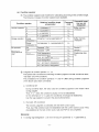
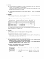
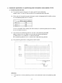
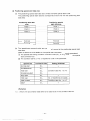
1
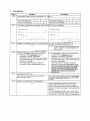
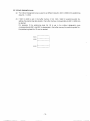
MlTSUBlSHl
PROGRAMMABLE CONTROLLER
Type A I SD75P1/P2/P3
AD75P1 /P2/P3
Positioning Unit
User’s Manual
<Supplementary Manuab
A MlTSUBlSHl ELECTRIC CORPORATION
BCN-P5133-*
1. Corrigenda
Positioning complete
Positioning complete
ON
OFF i
.
.
ON
E ! L l - u L r L U
EL
,
.
n
-L
Positioning
Positioning
I
3-37
3-44
Addition of precaution for start complete signal at start of external positioning run
......................................................................................
(b) Start of external positioning run
4) When starting with an external start
signal, the start complete signal will
not turn ON.
Addition and correction of point (1) details
...........................................
..........................................
(1) In interpolation control, only the travel
(1) In interpolation control, only the travel
direction of the applicable axis is
direction of the reference axis is
checked. Therefore, automatic
checked. Therefore, automatic
deceleration is not performed as long as
deceleration is not performed as long as
the travel direction on the reference axis
the travel direction on the reference axis
remains unchanged.
remains unchanged.
This may result in sudden direction
This may result in sudden direction
reversal on the other interpolation axis.
reversal on the other interpolation axis.
To avoid sudden reversal of the partner
axis, do not use the continuous path
control (1 1) for the passinq point, and
instead use continuous positioninq
control (01).
The positioning address and arc data for
each axis are used.
3-48
The positioning address and arc data set in
the same positioninq data No. for each axis
is used.
Addition of precaution for interpolation
--------------------------------------------------------------------------------------.
-
When interpolating with the continuous
positioning control and continuous path
control, interpolate from the first positioning
data No. to the (run pattern: 00) positioning
data No.
If the positioning data No. set in each point
for the positioning start data in block start is
interpolation, all points must be interpolation.
- 1 -
Mistake
Correction
Shange
of (7) (e) section
..........................................
..........................................
(e) Software
stroke
limit check
Software
(e) stroke
limit check
During execution of speed
control,
The
software
stroke
limit range will be
checking isnot performed as long as thechecked
at start up only whenthe"feed
travel value is withinthesoftwarestrokecurrentvalue
updateduringspeed
limit range.
control request" is ON.
If the travel value exceeds the software
stroke limit range, an error will occur at
the time of switching to position control,
and the axis will decelerate to a stop.
..........................................
(8) Designation of positioning data
The following positioning data is set in
the peripheral device and sequence
program.
Item
I Run oattern
I
Settina necessitv
I
0
I
Select: "Forward run
speed/position"
"Reverse run
soeed/oosition"
Control method
Acceleration time
Deceleration time
Positioning address/
movement rate
-
Circular address
Command soeed
I M code
A
I
A
I
:Remarks]
1) +1: Refer to section 3.4.5for details on the
positioning data.
2) ~ 2 :The setting necessity is indicated with the
following symbols.
0: Setting required
A : Setas required
-: Setting not required
3) +3: The "Forward run speed/position" and "Reverst
run speed/position" control methods are
selected according to the motor rotation
direction.
Zorrection
of point details
..........................................
The absolute original point is not changed
after any of the following control operations
s performed:
Present feed value 0 clear at the start
of fixed-pitch feed
Present feed value 0 clear during
speed control
Present feed value update request
command during speed control
...........................................
The absolute original point is not changed
after any of the following control operations
is performed:
Present feed value 0 clear at the start
of fixed-pitch feed
Present feed value update request
command
during
speed
control
Sorrection of (4) (d) section
..........................................
[d) For the manual pulse generator 1 pulse
(d) For the manual pulse generator I pulse
input magnification, set the value for the
input magnification, set the value for the
relevant axis.
relevant axis.
I f the maqnification is outside the settinq
The manual pulser will run with the
range, an axis error will occur, and
followinq values when the value is not in
manual pulse qenerator operation will not
the settinq range.
If the input scale per pulse of the
be performed. In such a case, input
pulses from the manual pulse will be
manual pulser is 101 or hiqher, the
iqnored.
pulser will run at 100.
If the input scale per pulse of the
manual pulser is 0 or less, the pulser
will run at 1.
_-------_-_-------------------------------,
2orrection
of (4) (a) section
..........................................
a) When the stop signal is turned ON
during JOG start, axis motion
decelerates to a stop.
h i s No.
~
~
~~~~
Buffer
Speed
change
value
1157,1156
memory
addressSpeedchange
1158
reauest
rentlent
1202,1201
1208
-
Stop immediately
when error is detected
-3-
-r
I
Correction
4ddition
to [Remarks] 1) Buffer memory address
.....................................................................................
Mistake
~~~
~
uring JOG operation and
manual pulse generator
Correction
of (4) (a) section
.....................................................................................
(a) If the electronic gear setting value is too (a) I f the electronic gear setting value is too
small, thespeed
may exceed the
great, the commanded speed may
speed control value, causing the
exceed the speed control value, causing
servomotor to operate at too high a
the servomotor to operate at too high a
speed,
speed.
Correction
of
(c)
section
.....................................................................................
c) Set the speed control limit, acceleration (c) When the M code ON signal is turned
time, deceleration time, and rapid stop
ON, the M code OFF request must be
turned ON with the sequence program,
deceleration time by specifying their
and the M code ON signal must be
respective parameters.
turned OFF.
If the M code ON signal is not turned
OFF, the process will be as shown belov,
according to the run pattern.
Correction
of (c) section
.....................................................................................
(c) A speed change can be executed at any (c) By turning the axis control data run
given point
during
the
following
speed
change
request
ON by
or
turning
positioning
operation by turning ON
the external signal external speed
ON, thespeedcanbechanged
either thepositioningspeedchangechange
request in thecontrol axis data or the
at arandompoint.
positioning external speed change signal
in the external signals.
Correction
of (2) (d) Buffer memory address ..........................................
..........................................
Reference .
axis
l3uffer memory
speed change
speed
request
@uffer memory
Reference
axis
AI speed change Speed change
request
Axis 1
1158
1156,1157
Axis 1
1156,1157
1158
Axis 2
1056,1057
1208
Axis 2
1206,1207
1208
Axis 3
1256,1257
1358
Axis 3
1256,1257
1258
Addition
of (9) explanation
.....................................................................................
(9) Even when the operation pattern is set to (9) Even when the operation pattern is set
to continuous locus control (1 l ) , an
continuous locus control (1 l ) , an
immediate speed change can be
immediate speed change can be
executed upon receiving a speed
executed upon receiving a speed
change request.
change request.
However, if the distance required to
chanqe to the designated speed is not
secured, the speed cannot be changed.
Zorrection
of (2) (a) section
.....................................................................................
[a) If the step enable signal has been turned (a) Set the step valid flag ON beforehand,
ON, the BUSY signal is turned ON when
andturnthepositioning start signal ON.
the positioning start signal is turned ON,
performing the first-point positioning
designated in the positioning start table.
- 4 -
I
Mistake
Correction
Page
Change of(2)(e) section
3-111 .___________-__-__------------------------...........................................
(e) If the step start information is set to OlH
(e) Once the first-point positioning has
started, the next positioning step is
while the axis run state is the step wait
performed if the step start data is set to
state, the next positioning step will be
01H when the axis operation status is
executed.
steD standbv.
Deletion of (2) (9
3-111 .------------------------------------------------------------------------------------(9 When step operation is performed
continuously, it is first confirmed that the
step start data is set to OOH (by the OS),
then the step start data is set to 01H.
3-111 .-----------------------------------------Correction of (2) (9) section
..........................................
(9) Once the first-point positioning has
(9) If the step start information is set to 01H
or 02H while the axis run state is the
started, the stopped processing of
restarts if the step start
step stop state, the stopped positioning positioning da
data is set to 01H or 02H when the axis
data will be restarted.
operation status is step-stopped.
3-112 .------------------------------------------------------------------------------------Correction of (2) (j) section
(j) When the axis operation status is step
(j) If the positioning start signal is turned
ON again while step waiting for the step
standby, step-stopped, or step error with
the step effective signal ON, the firstvalid signal ON, while step stopped or
during a step error, the step for
point positioning step will be performed
upon turning ON the positioning start
positioning the positioning No.
signal again.
designated with the positioning start No.
will be executed.
3-117 .-----------------------------------------Correction of buffer memory address
..........................................
... Set 500, in buffer memory address 1 1 3 8 .
Set 500, in buffer memory address 1105.
3-118 .------------------------------------------------------------------------------------Correction of buffer memory address
... Set 600, in buffer memory address 1 1 3 8 . . , . Set 600, in buffer memory address 1 1 0 5 .
... Set 500, in buffer memory address 1 1 3 8 . ... Set 500, in buffer memory address 1 1 0 5 .
3-120 .------------------------------------------------------------------------------------Addition of explanation to (2) (e)
(e) If it is not possible to secure a sufficient (e) If it is not possible to secure a sufficient
distance for this function to change the
distance for this function to change the
current speed to the designated override
current speed to the designated override
speed, the current speed is changed to
speed, the current speed is changed to
the highest possible speed within the
the highest possible speed within the
given distance.
given distance.
However, if the run pattern is the
continuous path control, the speed will
not be changed.
3-120 .--_--_-_-------________________________--Correction of (2) (h) section
(h) If the feed speed of 1 or less results from
setting an override value of 100% or less,
a warning (warning No.110) occurs, while
the feed is performed at the speed of "1
in the current meed units.
3- 120
I
T..,
'I
3-122
address is a ring address between 0 and
360".
-5-
address is a ring address between 0 and
359,99999".
Setting details
1
I
Axis 1 linear control (INC)
W n g details
Axis 1 linear
control
I
(ABS)
Axis 1 linear
control
llNCl
1I
Axis 1 inching control
Axis 2 linear interpolation control (ABS)
Command
code
01H
I
02H
I
04H
Axis 1 inchinacontrol
Axis 2 linearinterpolationcontrol
(ABS)
Axis 2 linear interpolation control (INC)
1~
-
Inching control of axis 2 with linear
interpolation
Circular interpolation control with
auxiliary point designation (ABS)
Circular interpolation control with
auxiliary point designation (INC)
Circular interpolation control with
center Doint desianation (ABS. CWl
Circular interpolation control with
auxiliary point designation (ABS)
I
Circular interpolation control with
0
Circular interpolation control with
auxiliary
designation
point
(INC)
08H
Circular interpolation control with
center point designation (ABS, CW)
09H
Circular interpolation control with
centerpointdesianation (ABS. CCWl
center point designation (INC, C M
Circular interpolation control with
center point designation (INC, CW)
Circular interpolation control with
center point designation (INC, CCW)
Circular interpolation control with
center point designation (INC, CCW)
Speedcontrol(forwardrun)
Speedcontrol(forwardrun)
Speed control (reverse run)
Soeedcontrol(reverserun)
Speed/position changeover control
(forward run)
Speed/position changeover control
(forward run)
I
ODH
OEH
Speed/position changeover control
(reverse run)
I
Current value change
Sorrection
of X4,. X5,. X6 section
..........................................
Inmanualpulse generator operation, itis
ON duringpositioninginaccordance with
pulse
input from the manual pulse
aenerator.
Manual pulser enable flag
OAH
I
4
Speed/position changeover control
(reverse run)
I
T
I
Current value change
11H
--------___-_--__------------------------.
During revised pathpulser run, theinmanual pulser enableflag ON will turn
ON.
7
Manual pulser enable flag
-6-
-
. ...._..._._I.I..
Mistake
Deletion of unit scale limits in table for (1)
.-----------------------------------------Unit
magnifi-
1: x1 times, 10: x10 times,
100: x100 times, 1000: x1000 times
[ Valid when the unit setting is mm,
inches or degrees, and invalid when it
is pulses.
A setting error occurs for values other
than the above. ]
Correction
..........................................
I TI
I II
Unit
magnifi-
I
1: x1 times, 10: x10 times,
100: x100 times, 1000: x1000 times
I
-100
1-1000001-1000001-1000001-100000
~ 1 0 - lL m~ 1 0 - I inch
I
~ 1 0 - dearee
l l
, ~ 1 0 - Dulse
'I '
I
Addition
of positioning start point No. area
.....................................................................................
-
11781228
1278 Positioning Set thestartpoint No.
startpointforexecutingposiNo.
tioning
(block
start).
1 to 50:
Start from
designated No.
Other than the above:
Start from the first
point
Change
of reference section
.....................................................................................
Monitor with the AD75 17-segment LED
Monitor with the AD75 17-segment LED
and LED for axis display.
and LED for axis display.
(Refer to section 4.7)
(Refer to section 4.6)
Change
of
details
explained
in
(Procedure
5)
(3).
.....................................................................................
(3) When the mode switch is pressed, the
(3) When the mode switch is pressed, the
condition is switched to internal
state of the input/output information n
information monitor 2, which is described
monitor shown in (Procedure 6) will be
in step 5.
moved to.
Zhange
of
program
example
(Deletion
of
MC
N1
Mi001
..........................................
T-
-7-
Page
6-7
Mistake
Correction
High speed
zero point return
start command X4
t---i [FROMP
HO K 8 1 7 DO K1
I
DO H8 D l 4
W
[-iANDP
7-11
M code OFF
HO
TOP[-/
K1153
Kg
Kl
4I
7-13
P
1150
Positioning start signal
1179
Positioningstartpoint
1178
-
No.
7-13
i
Start point No.
:buffer memory address
y:d r-,.,.:
7-14
TOP
' ' T F T O P
Positioning start point No.
HO
K 1 1 5 3 K7000 Kl
HO
uL,::
HO
'TOP
y;;j
K 1 1 5 3 K7000 K1
8-5
Do not turn OWOFF during jogging
Positioning start
complete (Xl)
Positioning start
complete (XI)
9-6
-
Pulser run
enable command
Pulser run
enable command
x4
-TOP
HO
K1167
HO
HO
HO
K1156
Dl0
Kld,
-1
x4
-[TOP
K 1 3i
HO
K 1 1D6l 70
HO
K1156
D8
K1
HO
K1171
K1
Kl
10-6
TOP
TOP
TOP
K1171
Kl
K1
D8
zi
K1
I
-
-8-
I
TOP
TOP
HO
K1
K1
3
4
4
I
Mistake
Page
12-6
044
H
o (Do not
run
pulser)manual pulser)
manual
logic)
29
Manual
pulser
selection
30 Select pulse
output logic to
drive unit
12-7
-9-
Correction
0 (Do not run
2. Additional explanation on condition data
(section 3.4.7)
The conditiondata is used to judgeconditions whenexecuting
simultaneous start.
conditional start, wait start and
The condition data can be created in the buffer memory as condition data No. 1 to 10.
I
Axis No.
I
Axis 3
4900-4990
One conditiondata itemis configured of acondition
parameter 1, parameter 2).
Configuration of
condition data
Condition identifier
Parameter 1
identifier and threeparameters
(address,
. . . . . . . . . . . 16-bit
. . . . . . . . . . . 16-bit
Address
I-
I
Buffer memory address
,
-1
, , , , , , ,
.
, ,
32-bit
. . . . . . . . . . . 32-bit
The range of each parameter in the condition data is checked when the positioning data No. is
executed. If the setting of each parameter in the condition data is not within the range, an error will
occur and the data will not be executed.
(1) Condition identifier
The condition identifier has a condition target and condition operator for judging the condition.
(a) Condition target
The target for condition judgment is set in the condition target.
The following five types of condition targets are available.
Condition target
Command code
Device X
Device Y
I Buffer
memory
02 I4
(16-bit)
Buffer memory (32-bit)
Positionina data
I
03 H
I
04 ti
05
- 10 -
.......
.............
....
(b)Condition
operator
0 The condition operatorsets the method for calculating according to the conditiontarget.
The following 14 types of condition operators are available.
Relation of condition target
and parameter
Condition operator
_
_
~
Normal operator
1-
n = (parameter 1)
1
#
n f (parameter 1)
2,
I
n
5
(parameter 1)
3H
L
n
L
(parameter 1)
4,
Range
designation 1
(Parameter I ) 5 n s (parameter 2)"
_ _ _ _ _ _ _ ~ ~
~~~
Command target
that can be
designated
Command
cod e
Buffer memory
(1 6/32-bit)
~
Range operator
L (parameter
Range
designation 2
Bit operator
Simultaneous
start
Parameter 1 ON
OFF
I Parameter 1 OFF
Axis
designation
6 n
l ) , n L (parameter 2)
ON
Buffer memory
(1 6/32-bit)
5H
I
Axis 1 designation
7,
Device X
8,
I Device Y
Positioning data
No.
9,
-
Axis 2 desianation
I
Axis 1 and Axis 2 designation
A,
B,
IeGdesignation
I Axis 1 and Axisdesignation
3
1 Axisand
2
Axisdesignation
3
I
I
D,
E
I
I
@ Judgment of condition operator "=", " f "
The special start commands for executing condition judgment include'Conditional start",
"wait start" and "FOR (condition)".
differ during condition judgment
The processes of the condition operators "=" and
of the above special start commands.
'I#"
a. Conditional start
During conditional start, the value used for condition judgment is the instant value
during judgment.
Thus, if "="is used, the conditions usually will not be established.
On the other hand, if " f "is used, the conditions will always be established.
Use the range operator to prevent the above phenomenon.
b. Wait start, FOR (condition)
The condition judgment is controlled with the AD75 control cycle.
Thus, even if the conditions are not established with the current control cycle, if they
are established at the next control cycle, wait and FOR will be completed.
[Remarks]
1) *1: During range designation 1, an error will occur if (parameter 1) > (parameter 2).
- 11
-
(2) Address
(a) The address is used to designate thebuffermemory address used when the condition
operator is a "normal operator" or "range operator".
The condition judgment is done with the value of the buffer memory designated with the
address and the parameter 1 and 2 values.
(b) The address is not used when the condition target is "device X", "device Y or "positioning
data No.".
(3) Parameter 1
(a) Parameter 1 is thedata setwhen thecondition operatoris
operator", "bit operator" or 'positioning data No.".
a"normal operator", "range
(b) The data that is set differs according to the operator being used.
Condition target Bit operator
Normal operatorhange operator
-
Device X
Device Y
Imemory
Buffer
Imemory
Buffer
(16-bit)
(32-bit)
I
I
Numerical
value
Numerical
value
Bit No.
Bit No.
I
I
-
I
I
If the condition operator is "simultaneous start", the positioning data No.of the partner axis to be
simultaneously started is set. (Refer to (5).)
(4) Parameter 2
(a) Parameter 2 is used to set the data required for the range operator.
(b) Only numerical value data can be set in parameter 2.
If the condition operator is "simultaneous start", the positioning data No. of the partner axis
to be simultaneously started is set. (Refer to (5).)
(5) Setting
of parameter 1 and parameter
2 for simultaneous start
(a) When the condition operator is simultaneous start, parameters 1 and 2 are used to set the
positioning data No. of the axis to be simultaneously started.
Forexample, if linear interpolation of axes 1 and 2 and axis 3 are to be simultaneously
started, the positioning data No. for axis 1 and axis 3 is set.
(b) The axis 1 to 3 positioning data No. is set as shown below.
(The areas used with axis 1 to 3 are fixed.)
- Parameter 1
- Parameter 2
.....
....,
.,...
.....
Positioning data No. foraxis 1 (parameter 1 low-order 16-bit)
Positioning data No. for axis 2 (parameter 1 high-order 16-bit)
Positioning data No. for axis 3 (parameter 2 low-order 16-bit)
Not used
(parameter
high-order
2
- 12 -
16-bit)
3. Additional explanation on positioning start information area (section 3.6.6)
(1) Positioning start data area
(a) The positioning start data area is the area used for block positioning.
Areas for point 1 to point 50 are provided for the positioning start data area.
(b) Which point of the positioning start data area to start is designated with the buffer memory
for the positioning start point No. setting.
Buffer memory address
Axis 1
1178
2
1228 Axis
3
1278 Axis
If the run is started without setting the buffer memory for positioning start point No. setting,
the run will start from point 1.
(c) The "format" and "positioning data No." are set in the positioning start data.
(Refer to section 3.4.6 for details on the format and positioning data No.)
0 Either "End: 0 : or "Continue: 1 is set for the format.
A positioning data No. from 1 to 600 is set in the positioning data No.
'I
a
(d) The positioning data area is configured as shown below.
bO
b15b14
Point 1
Point 2
Point 3
Point 49
Point 50
- -
k Positioning data No.
(1
600)
4
Format
End
:0
Continue: 1
[Remarks]
1) * : The data No. for which positioning control is to be executed is set in the positioning data
No.
- 13 -
(2) Positioning special startdata area
(a) The positioning special start data area is where the AD75 special start is set.
The positioning special start data area corresponds one-on-one with the positioning start
data area.
Positioning
special
Positioning
data start
area
data
Point
.............
.............
.............
Point 50
.............
.............
Point 2
3
start
area
I
)
Point 2
Point 3
(b) The 'special start command code" and "parameter" are set in the positioning special start
data area.
(Refer to section 3.4.6 for details on the special start command codes and parameters.)
0 The special start starting condition command code (00 to 07 H) isset for the special
start command code.
0 The condition data No. or No. of repetitions is set in the parameter.
,
Special start
Command code
Setting parameter
00 H
-
Normal start
O1
H
Wait start
Conditional start
Simultaneous start
02 H
Stop start
O4
H
FOR loop
O5
H
FOR condition
06 ti
07
NEXT
Condition data No. 1 to 10'
03 H
No. of repetitions (0 to 255)
Condition data No. 1 to 10'
-
[Remarks]
1)
1;
: Which of the (3) condition data items to be used is set in the condition data NO.
- 14
....
____
.... .............
-.
.
.
.-
-.
I
....
.........
-
(d) The positioning special start data area is configured as shown below.
r
b15
b8 b 7
z
bO
5
i
Point 1
Point 2
Parameter
Condition data No.
No. of repetitions
command code
(Oo H
O7 n)
I
(3)
Condition dataarea
(a) The condition designated with the positioning special start data area parameter is set in the
condition data area.
The condition data area has ten areas from 1 to 10.
(Refer to the AlSD75Pl/P2/P3, AD75Pl/P2/P3 type Positioning Unit User's Manual (Details
section), section 3.6.6 for details on the condition data area configuration.)
(c) The following data is set in each item of the condition data area.
0 The "condition target command code" and "condition operator command code" are set
in the condition identifier.
(Refer to section 3.4.7 (1) for details on the condition target commandcodeand
condition operator command code.)
I
b15
?
;o,"ni;frn
i
[
-
b12bll
-
b7 b8
bO
h
I'
I
bCondition target command code
(01 y'
-
05 n)
aCondition operator command code
(01 H
0 Refer to section 3.4.7 (2) to (5) for details on the
2.
15 -
e-
OE n)
address, parameter 1 and parameter
(4) Indirect designationarea
(a) The indirect designation area is used to set different data No. 8001 to 8050 in the positioning
data No. 1 to 600.
(b) I f 8001 to 8050isset
in the buffermemory (1 150, 1200,1250) for positioning start No.
setting, the positioning data storedin the buffer memory corresponding to 8001 to 8050 can
be started.
For example, if thepositioningdata
No. 53 isset
in theindirectdesignation
area
corresponding to 8001, and 8001 is designated in the buffer memoryfor positioning start No.,
the positioning data No. 53 can be started.
c-----l
?--t
8o02
8050
A
MITSUBISHI
PROGRAMMABLE CONTROLLER
Technical News
Subject: Precautions for replacing A I SD71/AD71 with A I SD75PO/AD75PO,
and connections with MR-H/MR-J
Applicable models: A I SD75P1, A I SD75P2, A I SD75P3,
AD75P1, AD75P2, AD75P3
Thank you for your continued patronage of the Mitsubishi general purpose sequencer MELSEC-A
Series.
The precautions for replacing the AlSD71S2 (S7) type positioning unit/AD71 (Sl, S2, S7) type
positioning unit with the AlSD75PO type positioning unit/AD75PO type positioning unit, and
3xamples for connecting with the MR-H/MR-J type servomotor are explained in this paper.
1.
Precautions for replacing AlSD71/AD71 with AlSD75/AD75
The precautions for replacing A1 SD71/AD71 with AlSD75/AD75 are described in this section.
(Refer to the AlSD75PCVAD75PO User’s Manual (Details Section) for comparisons of the
A1 SD71/AD71 and AlSD75/AD75 functions.)
(1) The pulse output logic and connector pin layout differ in the AlSD75/AD75 type. Refer to
Technical News PLC-D-245 for details on the pulse output logic.
Item
A 1S D75/AD75
Connector used
No. of connectors
AlSD71/AD71
Connector: 101 36-3000VE
Connector: FCN-361J040-AU
: 10336-56FO-008
Cover
Cover
: FCN-360C040-B
(Sumitomo 3M)
(Fujitsu)
One/axis (Enclosed with unit for
One/unit
No. of axes being used)
Connector pin layout
The pin Nos. for each axis have the The X axis or Y axis is
same application.
designated with the pin No.
Zero point signal
specifications
Correspond to DC5V/DC24V
(When using MR-H/MR-J, use the
DC24V power supply. (Refer to the
connection examples.))
Correspond to DC5V to DC24V
Manual pulser model
MR-HDPO1
OSM-O1-2(C)
(Mitsubishi Electric)
(Nemicon)
(2) When connecting the AlSD75 with peripheral equipment, a convertor cable (AlD75-C01H) is
required.
Mitsubishi Electric Corp., Nagoya Works
Recommendedconnections
2.
The open collector method or differential driver method is used for the AlSD75PO/AD75PO
pulse train output.
Generally, the differential driver method has a stronger resistance to noise than the open
collector method, so connection of the AISD75PU/AD75PU to a drive unit with the differential
driver method is recommended. However, the load current of the AlSD75PCI/AD75PO
differential driver is 20mA, so the differential driver must be used in the above specifications
range.
3. Connection with drive unit
-
Generally, the drive unit (servo amplifier, stepping motor driver) command pulse input section
is photo coupler insulated with the open collector input.
The connection with the open collector input drive u'nit will be described below.
Connection of the AISD75PO/AD75PO and drive unit with a differential driver method is
recommended to increase the noise margin. (Refer to Fig. 1.)
SD75PO/AD75PO
Drive unit
AI
I
h
L
I
Fig. 1 Example of connection to AlSD75PWAD75PO differential driver
Mitsubishi Electric Corp., Nagoya Works
(213)
. ..
When connecting the AlSD75PO/AD75PO and drive unit with an open collector method, wire
as shown in Fig. 2.
Drive unit
AlSD75POIAD75PO
I
?
Fig. 2 Example of connection to AlSD75PWAD75PO open collector
4.
AlSD75PWAD75PEIcommand pulselogic
There are some products that will not accept the command pulse if the command pulse logic
does not match at the servo amplifier or stepping motor driver.
I f the AlSD75PCYAD75PO and servo amplifier/stepping motor driver logic do not match, use 6
differential driver output, and cross the wiring as shown in Fig. 3.
In this case, the open collector method cannot be used.
Drive unit
A1SD75PQJAD75PO
I
Fig. 3 Example of wiring in which command pulse logic does not mach
When connecting the AlSD75PO/AD75PO and a Mitsubishi servo amplifier, the logic can be
changed with the servo amplifier parameter settings. However, the normal wiring shown in Figs.
1 and 2 must be used.
Mitsubishi Electric Corp., Nagoya Works
A
MITSUBISHI
PROGRAMMABLE CONTROLLER
Technical News
Subject: External connection wiring for A I SD75PU/AD75PO
Applicable models: A I SD75P1, A I SD75P2, A I SD75P3,
AD75P1, AD75P2, AD75P3
hank you for your continued patronage of the Mitsubishi general purpose sequencer MELSEC-A
'eries.
he method for connecting the AlSD75PO type positioning unit and the AD75PO type positioning
nit with the drive unit will be described in this paper.
.
AlSD75PU/AD75PU pulse output specifications
In the AlSD75PO/AD75PO, a pulse train is output to the drive unit and the positioning is
controlled.
The "SING pulse output", "CW/CCW pulse output" and 'A phase/B phase pulse output" types
are available for the AlSD75PO/AD75PO pulse outputs. The type to be used is set with the
basic parameter 1 of the AlSD75PO/AD75PO.
The A1 SD75PO/AD75PO pulse outputs are shown in Table 1.
Table 1 AlSD75PWAD75PO pulse output
c
Forward run
SING pulse output
PULSE
High
Low
SING
High
Low
PULSE F
High
Low
PULSE R
High
Low
A phase/B phase pulse A phase
output
High
Low
B phase
High
Low
CW/CCW pulse output
I
Reverse
run
II
1
nnnn
nnnn
qemarks]
) "High" and "Low' for the AlSD75PO/AD75PO open collector method (transistor output) are as
explained below.
High: AlSD75PO/AD75PO pulse output transistor is OFF.
LowAlSD75PO/AD75PO pulse output transistor is ON.
Mitsubishi Electric Corp., Nagoya Works
I
..
. .. .-
..
2.
Example of AlSD75lAD75 and MR-J connection
(1) When using differential driver
. ,. .. .Regenerative option
. .
Servomotor
.........
Servo amplifier
NFB
MC
FR-BAL
Power supply
AC200V-230Y
50Hz/60Hz
1
tl
lSD75IAD75
CN1
*3
*3
lser (MR-HDW1)
Torque limlt command
+ 10VImax current
Mcnttor M a x . + t m A meter
Single sway
[Remarks]
1) - 1 : The applications of the AlSD75/AD75 connector pin Nos. are common for axis 1 to axis 3.
2) t2: The AlSD75/AD75 upper limit limit (FLS) and lower limit limit (RLS)are used by the retry function during
point return. Set these to the inner side with the servo limit switch.
3) -3: This is the limit switch for the servo (for stopping).
Mitsubishi Electric Corp., Nagoya Works
zero
(2) When using open collector
Regenerawe optlon
Servomotor
.........
c i fry
n
I
NFB
MC
FR-BAL
.
Servo amplifier
MRJ
'
Power supply
AC200V-230V
~,.
'
P
I
*I
j
CHI
7
I
I
i I? I 9 6
I
*3
*3
L
. ..
Manualpulser (MR-HDW1)
Torque lfmit mmmand
+lOV/max current
Monitor Max + 1mA meter
Single sway
Wthin 3m
1
lOkQ
Withln 2m
I
[Remarks]
1) tl: The applications of the AlSD75/AD75 connector pin Nos. are common for axis 1 to axis 3.
2) +2: The AISD75/AD75 upper limit limit (FLS) and lower limit limit (RLS) are used by the retry function during
point return. Set these to the inner side with the servo limit switch.
3) t3: This is the limit switch for the
servo (for stopping).
zero
3.
Example of AlSD75/AD75 and MR-H connection
(1) When using differential driver
.
..
Ready
RA2
EHG
OFF
Reaenerattve ontion
OY
Servomotot
Power supply
ACZ00i1-Z30V
50Hz/60Hz
*I
1SD75/AD75
c
I
1 rn
...- -.. \,".,
~
US &
~
STOP
CHG
E
15
Lower lhrnit limit
12
i
PP
'
1 SON
stop
Speediposition change
*3
*3
~
IE:
nOG
Monitor 1
Monitor 2
J
Wfihin
2m
Torque limii mrnmand ( + )
+ 10Vima.x
current
Torque lhrnit m m m a n d
-1OVlmax. current
(-1
[Remarks]
1) tl: The applications of the AlSD75/AD75 connector pin Nos. are common for axis 1 to axis 3.
2) t2: The AlSD75/AD75 upper limit limit (FLS) and lower limit limit (RLS) are used by the retry function during
point return. Set these to the inner side with the servo limit switch.
3) +3: This is the limit switch for the
servo (for stopping).
Mitsubishi Electric Corp., Nagoya Works
zero
(2) When using open collector
Regenerative opllon
~
-
AC200V-230V --o
50Hz/60Hz
Servo ampiher
MR-HGA
Servomotor
~
. . . .. .. .
3
1
I i
*I
A 1SD75/AD75
rI
I A n I sc
I
Reverse run stroke end
13 TL
38 LSP
. 39 LSN
I
u
I
I
I
J *3
I
.
......
~
1 *3
C63
1
~
37 CR
17 1 SG
Monitor 1
Monitor 2
I
Lt
Within 2m
4
Torque limit command (tj
+ 10Vimax current
Torque limit command (-)
-10Vima.x current
Wlthin 3m
[Remarks]
1) t l : The applications of the AlSD75/AD75 connector pin Nos. are common for axis 1 to axis 3.
2 ) * 2 : The AlSD75/AD75 upper limit limit (FLS) and lower limit limit (RLS) are used by the retry function during
point return. Set these to the inner side with the servo limit switch (+3).
3) *3: This is the limit switch for the servo (for stopping).
Mitsubishi Electric Corp., Nagoya Works
zero
A MlTSUBlSHl ELECTRICCORPORATION
H E A D O F F I C E HITSUBISHI D E N K I ELDG MARUNOUCHI T O K Y O 1 0 0 TELEX J21532 C A B L E M E L C O T O K Y O
NAGOYA WORKS 1 . 1 4 V A D A - M I N A M I 5 , HIGASHI.KU
NAGOYA
JAPAN
When exported from Japan,
this manualdoesnotrequireapplication
to the
Ministrv of International Trade and lndustrv for service transaction permission.
BCN-P5133-* (9601) MEE
Japan
Printed
Specifications
in
change
subject
without
to notice.
1