1
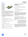
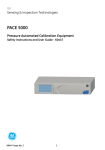
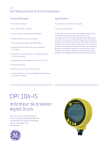
GE Industrial
Sensing
Druck PV211 - Pneumatic
pressure and vacuum pump
K408 Issue 1
KEY
1.
2.
3.
4.
5.
6.
7.
8.
Pressure release valve
Fine adjust vernier
Pressure/Vacuum selector
Quick-fit connectors
3 ft long x 1/8” diameter flexible nylon hose
1/4” female NPT adapter
Scissor handles
Overpressure protection: Adjustable stroke control to adjust
the maximum pressure output per stroke
9. Pressure Port: 1/4” NPT female adapter for connection to a
reference instrument (Example: digital/analog gauges)
10. Seal
SPECIFICATION
Pressure:
Vacuum:
Materials:
Dimensions:
Weight:
0 to 600 psi
0 to -28 in. Hg
Bright nickel plated brass, anodized
aluminum, phosphor bronze (springs), nitrile,
nylon
8.5”L x 4”W x 2.5”D
1 lb
DESCRIPTION
This system is a portable source of pressure and vacuum. Each pump includes a pressure/vacuum selector, a volume
control for fine adjustment and an adjustable stroke to give overpressure protection.
Note: Because it has a small displacement, only use the system to pressurize small volumes.
HOSE/ADAPTERS
To attach a hose (5) and adapter (6) to a connector (4), turn the knurled nut on the connector counterclockwise.
PRESSURE RELEASE VALVE (1)
Use this to reduce or release the pressure in the system. The amount of turn sets the rate to release the pressure. Only
minimum force is necessary to seal the system.
FINE ADJUST VERNIER (2)
To make accurate adjustments to the pressure, turn the fine adjust vernier clockwise to increase
the pressure or counterclockwise to decrease the pressure.
IMPORTANT: To prevent damage, DO NOT use force to turn the fine adjust vernier (2)
farther than the red line indicator on the thread.
PRESSURE/VACUUM SELECTOR (3)
Before you change the mode, make sure that the pressure release valve (1) is open. To change
the mode, use an applicable tool to push the selector (3) to the side specified on the label.
Red line indicator
OVERPRESSURE PROTECTION (8)
To adjust the maximum output pressure of the system, turn the nuts (8) to increase or decrease the stroke length.
Web: www.gesensing.com
Operating instructions for the Druck PV211 - Pneumatic pressure and vacuum pump
GUIDELINES FOR OPERATION
WARNING - HIGH PRESSURE
•
•
1.
Uncontrolled release of high pressure is dangerous and may cause damage to equipment. Because the
internal pressure can get very high during operation, make sure that all the connections are made
correctly. DO NOT ignore the maximum operating pressure specified on the pump label.
Before you connect a pressure component to the PV211, make sure that it is isolated from the pressure
supply and release the internal pressure slowly. DO NOT connect the pump to an external pressure source.
Calibration/Comparison against an analog gauge.
1.1. Connect a reference instrument to the pressure port at the top of the pump (9).
1.2. Connect the instrument under test to the connection at the end of the flexible hose (5).
Note: The maximum torque for the adapters is 11 ft-lb.
1.3. Set the fine adjust vernier (2) to the midpoint of its travel:
Turn it fully clockwise, then four to six turns counterclockwise.
1.4. Close the pressure release valve (1):
Turn it fully clockwise, and tighten to seal.
1.5. Operate the scissor handles (7) until the pressure is almost correct. To get the maximum pressure output,
squeeze the handles fully together on each stroke.
1.6. To adjust the pressure to the correct value, turn the fine adjust vernier (2) clockwise to increase the pressure
or counterclockwise to decrease the pressure.
Caution! To prevent damage, DO NOT use force to turn the fine adjust vernier (2)
farther than the red line indicator on the thread.
Note: Initially, small pressure changes can occur (thermodynamic effects, the seals settle, the hoses expand).
The pressure will stabilize after a short time.
1.7. You can also decrease the pressure by careful operation of the pressure release valve (1).
1.8. To get a vacuum, set the pressure/vacuum selector (3) to the vacuum position (as indicated on the pump
label) then use the same procedure as above.
Note: Before you change the mode, release the pressure.
2.
Operation with a high-resolution pressure calibrator:
Because the resolution is better, it is possible you will see more of the small pressure changes identified in step 1.6
above.
Note: On very high resolutions such as 0.1 in. H2O, only a small movement of the hose is sufficient to see a pressure
change.
FAULT INVESTIGATION/MAINTENANCE
•
•
•
•
•
If the system appears to lose pressure, repeat the above procedure. Make sure: there is no damage to the seals,
the adapters are tightened sufficiently, the pressure release valve (3) is tightened sufficiently to seal.
Do not try to tighten the connections between the pump and the fine adjust vernier (2) or between the pump and
the quick-fit connectors (4). These are factory set and changes can cause damage to the sealed joints.
During leak tests, small air movements (in or out) are possible around the pressure/vacuum selector (3). This is
normal.
If the system has not been used for a period of time, it can be difficult to operate on the first stroke. It will become
free after this.
For seal replacement refer to the service kit IAS-A111-1 instructions.
2 of 2
K408 Issue 1