Transcript
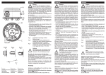
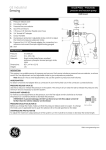
Operating instructions
Differential pressure, vacuum and overpressure switch
604
Caution
Before you take the pressure switch into
operation, make sure to read these operating instructions thoroughly. In the event of damages due to the
non-observance of these instructions, improper operation or use of the switch for purposes for which it is not intended, the warranty becomes null and void. We shall not
be held liable for resultant consequential damages. The
switch is to be installed and removed by technicians
only.
The applicable certified national safety regulations for the
operation of pressure measuring devices shall be observed.
In the installed condition the respective device-specific requirements on the type of protection must be fulfilled.
– Do not change adjustment of factory-adjusted and
paint-sealed switches (screw B and C).
– Screw C was adjusted in the factory, and the adjustment
fixed with adhesive. This asjustment may not be changed. Change the switching point with B screw only.
– Adjust upper and lower switching points with the dial
(B).
– In case of vacuum: connect P2
Adjustments as indicated in the instructions, except
pressure = vacuum.
– Fasten bracket to switch with original factory-supplied screws only.
Fig. 3
Fig.4
Fig. 5
Recommended installation arrangement vertical
(factory calibration).
Horizontal installation arrangement, electrical
connections upward. Actual switching points are
11 Pa higher than the scale.
Horizontal installation arrangement, electrical
connections downward. Actual switching points
are 11 Pa lower than the scale.
1 Supply cable
2 NC contact
3 NO contact
all fixing brackets
Note
With the safety cover removed, contact with terminals 1, 2 and 3 poses a lethal C hazard (mains
power voltage)!
Adjusting of upper/lower switching point
(Dial B: For higher switching point [higher pressure]
turn in clockwise direction.)
Allow pressure to increase gradually (do not exceed
max. pressure limit), adjust desired switching point with
dial (B).
Check the upper or lower switching points by raising
and lowering the pressure several times and make any necessary adjustments.
Note!
Adjust switch within printed-on scale only!
Do not turn the dial (B) into the area of the black mark
! [Switching contact changes from NC
(1-2) to NO (1-2).1
Tube connection