1
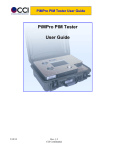
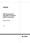
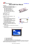
Pico Repeater
User Manual
(PRP-G1)
User Manual of PRP-G1
GSM Pico Repeater
Contents
1. Summary
2. System Configuration
2-1. System Operation
2-2. System Description
3. System Specifications
3-1. Electrical Specification
3-2. Mechanical Specification
4. Circuit Description
4-1. Forward Path (From BTS Towards Handset)
4-2. Reverse Path (From Handset Towards BTS)
5. System Block Diagram
6. Appearance
2/8
ASB lnc. 2004
User Manual of PRP-G1
GSM Pico Repeater
1. Summary
The PRP-G1 Pico Repeater is an indoor and increases a call quality and coverage in RFshaded small area by boosting up and repeating the GSM RF signals so that it can improve a
mobile service quality. It is suitable for the RF-shaded small area of any building or structure
such as basement, house, and so on. All system specifications can be provided with minor
modification for different GSM service frequencies. The system consists of a repeater unit with
a link antenna and service antenna.
2. System Configuration
2-1. System Operation
DONOR
ANT.
SERVICE
ANT.
중계기
Repeater
(Outdoor)
3/8
(Indoor)
ASB lnc. 2004
User Manual of PRP-G1
GSM Pico Repeater
2-2. System Description
A. External Configurations
(1) In/Out Terminal: SMA Female
(2) LED: To monitor the status of power on/off and normal operation
(3) Power Supply Terminal: External type AC-DC power supply
(Operating voltage: DC +8 V)
(4) Gain Control Switch: 2-pin dipswitch, manual gain control (4, 8, 12 dB)
B. Gain Control
A user can control the forward and reverse gain manually by using 2-pin dipswitch up to 12
dB with the interval of 4 dB, as shown in the figure below.
1
2
1
2
1
2
1
2
ATT
CTRL
ATT
0dB
ATT
4dB
ATT
8dB
ATT
12dB
C. ASD (Auto Shut Down) Function
The repeater has ASD function that controls its output power by real-time checking the signal output power of a forward path (BTS→Handset) and a reverse (Handset→BTS) path. If
the output power of the path exceeds a maximum output power rating of the repeater, the
DC power supply is automatically shut down to protect the circuits inside and a front LED
turns to the red-colored to indicate a warning.
4/8
ASB lnc. 2004
User Manual of PRP-G1
GSM Pico Repeater
3. System Specifications
3-1. Electrical Specification
Parameters
Specifications
System
System Group Delay
<5 ㎲
Self-generating Spurious Emission
< -67 dBm / 30 KHz (@max. gain)
Out Band Spurious Emission
< -36 dBm @ 9 KHz ~ 1 GHz
< -30 dBm @ 1 GHz ~ 12.75 GHz
Pass Band Ripple
4 dB (peak to peak)
Noise Figure
< 10 dB
Tx/Rx Isolation
> 65 dB
Characteristic Impedance
50 ohm
Input VSWR
1.5 : 1
Forward Path (BTS towards Handset)
Gain
50 dB Max. (Att. step 4 dB, range 12 dB)
Frequency Range
890 MHz~915 MHz
Input Power Range
< -45 dBm / Total
Maximum Output Power
0 dBm Max. / Total
Reverse Path (Handset towards BTS)
5/8
Gain
50 dB Max. (Att. step 4 dB, range 12 dB)
Frequency Range
935 MHz~960 MHz
Input Power Range
< -45 dBm / Total
Maximum Output Power
5 dBm Max. / Total
ASB lnc. 2004
User Manual of PRP-G1
GSM Pico Repeater
3-2. Mechanical Specification
6/8
Parameters
Standards
Dimension
104 mm X 64 mm X 42 mm (H X W X D)
Weight
550 g
Power Supply
AC-DC (+8 V) External Power Supply Adapter
Operating
Temperature/Humidity
-5 ~ +50 °C / 5% ~ 95%
Power Consumption
<6W
Input/Output
Connector Type
SMA Female
Radio type
G7W, D7W
Communication Method
Duplex Communication
ASB lnc. 2004
User Manual of PRP-G1
GSM Pico Repeater
4. Circuit Description
The input/output connector of the repeater is SMA Female type and a communication method is
Duplex Communication. The power supply is AC-DC (+8 V) external power supply adapter.
4-1. Forward Path (BTS towards Handset)
A signal from the BTS is received through the donor antenna of the repeater and the received input signal is isolated from a transmitter by a duplexer. This isolated signal is lownoise amplified and then it passes a variable attenuator. Then it is amplified at a second
stage and prior to final stage amplification the signal is filtered by a band-pass filter. The
output signal from the final amplifier is transmitted through the duplexer towards the service
antenna. A directional coupler monitors the output power level of the transmitting signal and
activates the ASD function if exceeding the maximum output power.
4-2. Reverse Path (Handset towards BTS)
The circuit of the reverse path is the same as that of the forward path. The signal from the
mobile handset is received by the service antenna of the repeater and transmitted through
the donor antenna. The directional coupler does the same way to provide the ASD function
in the reverse path.
7/8
ASB lnc. 2004
User Manual of PRP-G1
GSM Pico Repeater
5. System Block Diagram
6. Appearance
전원 (POWER)
장애 (WARNING)
8/8
ASB lnc. 2004