Download Description

Transcript
UM1052
User manual
STM32F103xx/ STM32F100xx/STM32F2xx/STM32F4xx
PMSM single/dual FOC SDK v3.2
Introduction
This manual describes the Motor Control Software Development Kit (generically called
software library) designed for and to be used with STM32F103xx, STM32F100xx,
STM32F2xx or STM32F4xx microcontrollers. The software library implements the Field
Oriented Control (FOC) drive of 3-phase Permanent Magnet Synchronous Motors (PMSM),
both Surface Mounted (SM-PMSM) and Internal (I-PMSM).
The control of an AC induction motor equipped with encoder or tacho generator is described
in the UM0483 user manual.S
The STM32F family of 32-bit Flash microcontrollers is based on the breakthrough ARM
Cortex™-M cores: the Cortex™-M3 for STM32F1xx and STM32F2xx, and the Cortex™-M4
for STM32F4xx, specifically developed for embedded applications. These microcontrollers
combine high performance with first-class peripherals that make it suitable for performing
both permanent-magnet and AC induction motor FOC.
The PMSM FOC library can be used to quickly evaluate ST microcontrollers and complete
ST application platforms, as well as to save time when developing Motor Control algorithms
to be run on ST microcontrollers. This PMSM FOC library is written in C language, and
implements the core Motor Control algorithms (reference frame transformations, currents
regulation, speed regulation, space-vector modulation, energy efficiency optimizations) as
well as sensor reading/decoding algorithms (three shunts, ST-patented single DC link shunt,
isolated current sensors, incremental encoder, hall sensors) and a sensorless algorithm for
rotor position reconstruction.
When deployed with STM32F103xx High-Density / XL-Density devices (Flash memory
density between 256 and 512 Kbytes / 768 Kbytes and 1 Mbyte), or STM32F2xx or
STM32F4xx, the PMSM FOC library enables simultaneous dual FOC of two different
motors. The library can be customized to suit user application parameters (motor, sensors,
power stage, control stage, pin-out assignment) and provides a ready-to-use Application
Programming Interface (API).
A user project has been implemented to demonstrate how to interact with the Motor Control
API. The project provides an LCD User Interface and a USART User Interface, represents a
convenient real-time fine-tuning and remote control tool for the motor control application.
A PC Graphical User Interface (GUI), the ST Motor Control Workbench, allows a complete
and easy customization of the PMSM FOC library. In conjunction with the ST motor control
starter kits, a PMSM motor can be made to run in a very short time using default
parameters.
Basic knowledge of C programming, C++ programming (for customizing the LCD User
Interface), PM motor drives and power inverter hardware is necessary for using the software
library.
March 2012
Doc ID 18458 Rev 3
1/127
www.st.com
Contents
UM1052
Contents
1
MC software development kit architecture . . . . . . . . . . . . . . . . . . . . . . 10
2
Documentation architecture . . . . . . . . . . . . . . . . . . . . . . . . . . . . . . . . . . 13
3
2.1
Where to find the information you need . . . . . . . . . . . . . . . . . . . . . . . . . . 13
2.2
Related documents . . . . . . . . . . . . . . . . . . . . . . . . . . . . . . . . . . . . . . . . . 14
Overview of the FOC and other implemented algorithms . . . . . . . . . . 15
3.1
Introduction to the PMSM FOC drive . . . . . . . . . . . . . . . . . . . . . . . . . . . . 15
3.2
PM motor structures . . . . . . . . . . . . . . . . . . . . . . . . . . . . . . . . . . . . . . . . . 17
3.3
PMSM fundamental equations . . . . . . . . . . . . . . . . . . . . . . . . . . . . . . . . . 18
3.3.1
3.4
PMSM maximum torque per ampere (MTPA) control . . . . . . . . . . . . . . . . 20
3.5
Feed-forward current regulation . . . . . . . . . . . . . . . . . . . . . . . . . . . . . . . . 22
3.6
Flux-weakening control . . . . . . . . . . . . . . . . . . . . . . . . . . . . . . . . . . . . . . 23
3.7
PID regulator theoretical background . . . . . . . . . . . . . . . . . . . . . . . . . . . . 25
3.7.1
A priori determination of flux and torque current PI gains . . . . . . . . . . . . 26
3.9
Space vector PWM implementation . . . . . . . . . . . . . . . . . . . . . . . . . . . . . 28
3.10
Detailed explanation about reference frame transformations . . . . . . . . . . 30
Current sampling in three-shunt topology . . . . . . . . . . . . . . . . . . . . . . . . 34
4.1.1
4.2
4.3
Tuning delay parameters and sampling stator currents in three-shunt
resistor topology 36
Current sampling in single-shunt topology . . . . . . . . . . . . . . . . . . . . . . . . 40
4.2.1
Definition of the noise parameter and boundary zone . . . . . . . . . . . . . . 43
Current sampling in isolated current sensor topology . . . . . . . . . . . . . . . 46
Rotor position/speed feedback . . . . . . . . . . . . . . . . . . . . . . . . . . . . . . . 49
5.1
Sensorless algorithm . . . . . . . . . . . . . . . . . . . . . . . . . . . . . . . . . . . . . . . . 49
5.1.1
5.2
2/127
Circle limitation . . . . . . . . . . . . . . . . . . . . . . . . . . . . . . . . . . . . . . . . . . . 32
Current sampling . . . . . . . . . . . . . . . . . . . . . . . . . . . . . . . . . . . . . . . . . . . 34
4.1
5
Regulator sampling time setting . . . . . . . . . . . . . . . . . . . . . . . . . . . . . . 25
3.8
3.10.1
4
SM-PMSM field-oriented control (FOC) . . . . . . . . . . . . . . . . . . . . . . . . . 19
A priori determination of state observer gains . . . . . . . . . . . . . . . . . . . . 50
Hall sensor feedback processing . . . . . . . . . . . . . . . . . . . . . . . . . . . . . . . 52
Doc ID 18458 Rev 3
UM1052
Contents
5.3
5.2.1
Speed measurement implementation . . . . . . . . . . . . . . . . . . . . . . . . . . 52
5.2.2
Electrical angle extrapolation implementation . . . . . . . . . . . . . . . . . . . . 54
5.2.3
Setting up the system when using Hall-effect sensors . . . . . . . . . . . . . 55
Encoder sensor feedback processing . . . . . . . . . . . . . . . . . . . . . . . . . . . 57
5.3.1
6
7
Working environment . . . . . . . . . . . . . . . . . . . . . . . . . . . . . . . . . . . . . . . 60
6.1
Motor control workspace . . . . . . . . . . . . . . . . . . . . . . . . . . . . . . . . . . . . . 61
6.2
MC SDK customization process . . . . . . . . . . . . . . . . . . . . . . . . . . . . . . . . 63
6.3
Motor control library project (confidential distribution) . . . . . . . . . . . . . . . 65
6.4
Motor control application project . . . . . . . . . . . . . . . . . . . . . . . . . . . . . . . 66
6.5
User project . . . . . . . . . . . . . . . . . . . . . . . . . . . . . . . . . . . . . . . . . . . . . . . 67
6.6
LCD UI project . . . . . . . . . . . . . . . . . . . . . . . . . . . . . . . . . . . . . . . . . . . . . 69
MC application programming interface (API) . . . . . . . . . . . . . . . . . . . . 73
7.1
8
Setting up the system when using an encoder . . . . . . . . . . . . . . . . . . . 58
MCInterfaceClass . . . . . . . . . . . . . . . . . . . . . . . . . . . . . . . . . . . . . . . . . . . 73
7.1.1
User commands . . . . . . . . . . . . . . . . . . . . . . . . . . . . . . . . . . . . . . . . . . . 74
7.1.2
Buffered commands . . . . . . . . . . . . . . . . . . . . . . . . . . . . . . . . . . . . . . . . 75
7.2
MCTuningClass . . . . . . . . . . . . . . . . . . . . . . . . . . . . . . . . . . . . . . . . . . . . 76
7.3
How to create a user project that interacts with the MC API . . . . . . . . . . 77
7.4
Measurement units . . . . . . . . . . . . . . . . . . . . . . . . . . . . . . . . . . . . . . . . . . 81
7.4.1
Rotor angle . . . . . . . . . . . . . . . . . . . . . . . . . . . . . . . . . . . . . . . . . . . . . . 81
7.4.2
Rotor speed . . . . . . . . . . . . . . . . . . . . . . . . . . . . . . . . . . . . . . . . . . . . . . 81
7.4.3
Current measurement . . . . . . . . . . . . . . . . . . . . . . . . . . . . . . . . . . . . . . 82
7.4.4
Voltage measurement . . . . . . . . . . . . . . . . . . . . . . . . . . . . . . . . . . . . . . 82
LCD user interface . . . . . . . . . . . . . . . . . . . . . . . . . . . . . . . . . . . . . . . . . 83
8.1
Running the motor control firmware using the LCD interface . . . . . . . . . . 83
8.2
LCD User interface structure . . . . . . . . . . . . . . . . . . . . . . . . . . . . . . . . . . 84
8.2.1
Motor control application layer configuration (speed sensor) . . . . . . . . 85
8.2.2
Welcome message . . . . . . . . . . . . . . . . . . . . . . . . . . . . . . . . . . . . . . . . 86
8.2.3
Configuration and debug page . . . . . . . . . . . . . . . . . . . . . . . . . . . . . . . . 86
8.2.4
Dual control panel page . . . . . . . . . . . . . . . . . . . . . . . . . . . . . . . . . . . . . 91
8.2.5
Speed controller page . . . . . . . . . . . . . . . . . . . . . . . . . . . . . . . . . . . . . . 92
8.2.6
Current controller page . . . . . . . . . . . . . . . . . . . . . . . . . . . . . . . . . . . . . 95
8.2.7
Sensorless tuning STO & PLL page . . . . . . . . . . . . . . . . . . . . . . . . . . . 97
Doc ID 18458 Rev 3
3/127
Contents
UM1052
8.2.8
9
10
11
Sensorless tuning STO & CORDIC page . . . . . . . . . . . . . . . . . . . . . . 100
User Interface class overview . . . . . . . . . . . . . . . . . . . . . . . . . . . . . . . 102
9.1
User interface class (CUI) . . . . . . . . . . . . . . . . . . . . . . . . . . . . . . . . . . . 103
9.2
User interface configuration . . . . . . . . . . . . . . . . . . . . . . . . . . . . . . . . . . 105
9.3
LCD manager class (CLCD_UI) . . . . . . . . . . . . . . . . . . . . . . . . . . . . . . . 106
9.4
Using the LCD manager . . . . . . . . . . . . . . . . . . . . . . . . . . . . . . . . . . . . . 107
9.5
Motor control protocol class (CMCP_UI) . . . . . . . . . . . . . . . . . . . . . . . . 107
9.6
Using the motor control protocol . . . . . . . . . . . . . . . . . . . . . . . . . . . . . . 108
9.7
DAC manager class (CDACx_UI) . . . . . . . . . . . . . . . . . . . . . . . . . . . . . . 109
9.8
Using the DAC manager . . . . . . . . . . . . . . . . . . . . . . . . . . . . . . . . . . . . . 111
9.9
How to configure the user defined DAC variables . . . . . . . . . . . . . . . . . 112
Serial communication class overview . . . . . . . . . . . . . . . . . . . . . . . . . 113
10.1
Set register frame . . . . . . . . . . . . . . . . . . . . . . . . . . . . . . . . . . . . . . . . . . 115
10.2
Get register frame . . . . . . . . . . . . . . . . . . . . . . . . . . . . . . . . . . . . . . . . . 118
10.3
Execute command frame . . . . . . . . . . . . . . . . . . . . . . . . . . . . . . . . . . . . 119
10.4
Execute ramp frame . . . . . . . . . . . . . . . . . . . . . . . . . . . . . . . . . . . . . . . . 120
10.5
Get revup data frame . . . . . . . . . . . . . . . . . . . . . . . . . . . . . . . . . . . . . . . 121
10.6
Set revup data frame . . . . . . . . . . . . . . . . . . . . . . . . . . . . . . . . . . . . . . . 122
10.7
Set current references frame . . . . . . . . . . . . . . . . . . . . . . . . . . . . . . . . . 123
Document conventions . . . . . . . . . . . . . . . . . . . . . . . . . . . . . . . . . . . . . 124
Appendix A Additional information. . . . . . . . . . . . . . . . . . . . . . . . . . . . . . . . . . . 125
A.1
12
4/127
References . . . . . . . . . . . . . . . . . . . . . . . . . . . . . . . . . . . . . . . . . . . . . . . 125
Revision history . . . . . . . . . . . . . . . . . . . . . . . . . . . . . . . . . . . . . . . . . . 126
Doc ID 18458 Rev 3
UM1052
List of tables
List of tables
Table 1.
Table 2.
Table 3.
Table 4.
Table 5.
Table 6.
Table 7.
Table 8.
Table 9.
Table 10.
Table 11.
Table 12.
Table 13.
Table 14.
Table 15.
Table 16.
Table 17.
Table 18.
Table 19.
Table 20.
Table 21.
Table 22.
Table 23.
Table 24.
Table 25.
Table 26.
Table 27.
Table 28.
Table 29.
Table 30.
Table 31.
Table 32.
Table 33.
Table 34.
Table 35.
Table 36.
Table 37.
Table 38.
Table 39.
Table 40.
References . . . . . . . . . . . . . . . . . . . . . . . . . . . . . . . . . . . . . . . . . . . . . . . . . . . . . . . . . . . . . 17
Sector identification . . . . . . . . . . . . . . . . . . . . . . . . . . . . . . . . . . . . . . . . . . . . . . . . . . . . . . 30
3-shunt current reading, used resources (single drive, F103 LD/MD) . . . . . . . . . . . . . . . . 35
3-shunt current reading, used resources (single drive, or dual drive, F103 HD, F2xx, F4xx).
36
Current through the shunt resistor . . . . . . . . . . . . . . . . . . . . . . . . . . . . . . . . . . . . . . . . . . . 40
single-shunt current reading, used resources (single drive, F103/F100 LD/MD) . . . . . . . . 41
single-shunt current reading, used resources (single or dual drive, F103HD, F2xx, F4xx) 42
ICS current reading, used resources (single drive, F103 LD/MD) . . . . . . . . . . . . . . . . . . . 47
ICS current reading, used resources (single or dual drive, F103 HD, F2xx, F4xx). . . . . . . 47
File structure . . . . . . . . . . . . . . . . . . . . . . . . . . . . . . . . . . . . . . . . . . . . . . . . . . . . . . . . . . . . 60
Project configurations . . . . . . . . . . . . . . . . . . . . . . . . . . . . . . . . . . . . . . . . . . . . . . . . . . . . . 69
Integrating the MC Interface in a user project. . . . . . . . . . . . . . . . . . . . . . . . . . . . . . . . . . . 77
MC application preemption priorities . . . . . . . . . . . . . . . . . . . . . . . . . . . . . . . . . . . . . . . . . 80
Priority configuration, overall (non FreeRTOS). . . . . . . . . . . . . . . . . . . . . . . . . . . . . . . . . . 80
Priority configuration, overall (FreeRTOS) . . . . . . . . . . . . . . . . . . . . . . . . . . . . . . . . . . . . . 80
Joystick actions and conventions . . . . . . . . . . . . . . . . . . . . . . . . . . . . . . . . . . . . . . . . . . . . 83
List of controls used in the LCD demonstration program . . . . . . . . . . . . . . . . . . . . . . . . . . 85
Definitions . . . . . . . . . . . . . . . . . . . . . . . . . . . . . . . . . . . . . . . . . . . . . . . . . . . . . . . . . . . . . . 87
List of DAC variables . . . . . . . . . . . . . . . . . . . . . . . . . . . . . . . . . . . . . . . . . . . . . . . . . . . . . 88
DAC variables related to each state observer sensor when two state observer speed sensors
are selected 89
Fault conditions list . . . . . . . . . . . . . . . . . . . . . . . . . . . . . . . . . . . . . . . . . . . . . . . . . . . . . . . 90
Control groups . . . . . . . . . . . . . . . . . . . . . . . . . . . . . . . . . . . . . . . . . . . . . . . . . . . . . . . . . . 93
Speed controller page controls . . . . . . . . . . . . . . . . . . . . . . . . . . . . . . . . . . . . . . . . . . . . . . 93
Control groups . . . . . . . . . . . . . . . . . . . . . . . . . . . . . . . . . . . . . . . . . . . . . . . . . . . . . . . . . . 95
Current controller page controls . . . . . . . . . . . . . . . . . . . . . . . . . . . . . . . . . . . . . . . . . . . . . 96
Control groups . . . . . . . . . . . . . . . . . . . . . . . . . . . . . . . . . . . . . . . . . . . . . . . . . . . . . . . . . . 98
Sensorless tuning STO & PLL page controls . . . . . . . . . . . . . . . . . . . . . . . . . . . . . . . . . . . 98
Control groups . . . . . . . . . . . . . . . . . . . . . . . . . . . . . . . . . . . . . . . . . . . . . . . . . . . . . . . . . 100
Sensorless tuning STO & PLL page controls . . . . . . . . . . . . . . . . . . . . . . . . . . . . . . . . . . 101
User interface configuration - Sensor codes. . . . . . . . . . . . . . . . . . . . . . . . . . . . . . . . . . . 105
User interface configuration - CFG bit descriptions . . . . . . . . . . . . . . . . . . . . . . . . . . . . . 106
Description of relevant DAC variables . . . . . . . . . . . . . . . . . . . . . . . . . . . . . . . . . . . . . . . 109
Generic starting frame . . . . . . . . . . . . . . . . . . . . . . . . . . . . . . . . . . . . . . . . . . . . . . . . . . . 114
FRAME_START byte . . . . . . . . . . . . . . . . . . . . . . . . . . . . . . . . . . . . . . . . . . . . . . . . . . . . 114
FRAME_START motor bits. . . . . . . . . . . . . . . . . . . . . . . . . . . . . . . . . . . . . . . . . . . . . . . . 114
Starting frame codes. . . . . . . . . . . . . . . . . . . . . . . . . . . . . . . . . . . . . . . . . . . . . . . . . . . . . 115
List of error codes . . . . . . . . . . . . . . . . . . . . . . . . . . . . . . . . . . . . . . . . . . . . . . . . . . . . . . . 116
List of relevant motor control registers . . . . . . . . . . . . . . . . . . . . . . . . . . . . . . . . . . . . . . . 116
List of abbreviations . . . . . . . . . . . . . . . . . . . . . . . . . . . . . . . . . . . . . . . . . . . . . . . . . . . . . 124
Document revision history . . . . . . . . . . . . . . . . . . . . . . . . . . . . . . . . . . . . . . . . . . . . . . . . 126
Doc ID 18458 Rev 3
5/127
List of figures
UM1052
List of figures
Figure 1.
Figure 2.
Figure 3.
Figure 4.
Figure 5.
Figure 6.
Figure 7.
Figure 8.
Figure 9.
Figure 10.
Figure 11.
Figure 12.
Figure 13.
Figure 14.
Figure 15.
Figure 16.
Figure 17.
Figure 18.
Figure 19.
Figure 20.
Figure 21.
Figure 22.
Figure 23.
Figure 24.
Figure 25.
Figure 26.
Figure 27.
Figure 28.
Figure 29.
Figure 30.
Figure 31.
Figure 32.
Figure 33.
Figure 34.
Figure 35.
Figure 36.
Figure 37.
Figure 38.
Figure 39.
Figure 40.
Figure 41.
Figure 42.
Figure 43.
Figure 44.
Figure 45.
Figure 46.
Figure 47.
Figure 48.
6/127
MC software library architecture . . . . . . . . . . . . . . . . . . . . . . . . . . . . . . . . . . . . . . . . . . . . . 10
Motor control library . . . . . . . . . . . . . . . . . . . . . . . . . . . . . . . . . . . . . . . . . . . . . . . . . . . . . . 11
Example scenario . . . . . . . . . . . . . . . . . . . . . . . . . . . . . . . . . . . . . . . . . . . . . . . . . . . . . . . . 12
Basic FOC algorithm structure, torque control . . . . . . . . . . . . . . . . . . . . . . . . . . . . . . . . . . 16
Speed control loop . . . . . . . . . . . . . . . . . . . . . . . . . . . . . . . . . . . . . . . . . . . . . . . . . . . . . . . 16
Different PM motor constructions . . . . . . . . . . . . . . . . . . . . . . . . . . . . . . . . . . . . . . . . . . . . 17
Assumed PMSM reference frame convention . . . . . . . . . . . . . . . . . . . . . . . . . . . . . . . . . . 18
MTPA trajectory . . . . . . . . . . . . . . . . . . . . . . . . . . . . . . . . . . . . . . . . . . . . . . . . . . . . . . . . . 21
MTPA control . . . . . . . . . . . . . . . . . . . . . . . . . . . . . . . . . . . . . . . . . . . . . . . . . . . . . . . . . . . 21
Feed-forward current regulation . . . . . . . . . . . . . . . . . . . . . . . . . . . . . . . . . . . . . . . . . . . . . 23
Flux-weakening operation scheme . . . . . . . . . . . . . . . . . . . . . . . . . . . . . . . . . . . . . . . . . . . 24
PID general equation . . . . . . . . . . . . . . . . . . . . . . . . . . . . . . . . . . . . . . . . . . . . . . . . . . . . . 25
Time domain to discrete PID equations . . . . . . . . . . . . . . . . . . . . . . . . . . . . . . . . . . . . . . . 26
Block diagram of PI controller . . . . . . . . . . . . . . . . . . . . . . . . . . . . . . . . . . . . . . . . . . . . . . . 26
Closed loop block diagram . . . . . . . . . . . . . . . . . . . . . . . . . . . . . . . . . . . . . . . . . . . . . . . . . 27
Pole-zero cancellation . . . . . . . . . . . . . . . . . . . . . . . . . . . . . . . . . . . . . . . . . . . . . . . . . . . . 27
Block diagram of closed loop system after pole-zero cancellation . . . . . . . . . . . . . . . . . . . 28
Vα and Vβ stator voltage components . . . . . . . . . . . . . . . . . . . . . . . . . . . . . . . . . . . . . . . . 29
SVPWM phase voltage waveforms . . . . . . . . . . . . . . . . . . . . . . . . . . . . . . . . . . . . . . . . . . 29
Transformation from an abc stationary frame to a rotating frame (q, d) . . . . . . . . . . . . . . . 31
Circle limitation working principle . . . . . . . . . . . . . . . . . . . . . . . . . . . . . . . . . . . . . . . . . . . . 32
Three-shunt topology hardware architecture . . . . . . . . . . . . . . . . . . . . . . . . . . . . . . . . . . . 34
PWM and ADC synchronization . . . . . . . . . . . . . . . . . . . . . . . . . . . . . . . . . . . . . . . . . . . . . 35
Inverter leg and shunt resistor position . . . . . . . . . . . . . . . . . . . . . . . . . . . . . . . . . . . . . . . . 36
Low-side switch gate signals (low modulation indexes) . . . . . . . . . . . . . . . . . . . . . . . . . . . 37
Low side Phase A duty cycle > DT+TN . . . . . . . . . . . . . . . . . . . . . . . . . . . . . . . . . . . . . . . 38
(DT+TN+TS)/2 < ΔDutyA < DT+TN and ΔDutyAB < DT+TR+TS . . . . . . . . . . . . . . . . . . . . . . 38
ΔDutyA < (DT+TN+TS)/2 and ΔDutyA-B>DT+TR+TS . . . . . . . . . . . . . . . . . . . . . . . . . . . . . . 39
ΔDutyA<(DT+TN+TS)/2 and ΔDutyA-B<DT+TR+TS . . . . . . . . . . . . . . . . . . . . . . . . . . . . . . . 39
Single-shunt hardware architecture . . . . . . . . . . . . . . . . . . . . . . . . . . . . . . . . . . . . . . . . . . 40
Single-shunt current reading. . . . . . . . . . . . . . . . . . . . . . . . . . . . . . . . . . . . . . . . . . . . . . . . 41
Boundary between two space-vector sectors . . . . . . . . . . . . . . . . . . . . . . . . . . . . . . . . . . . 42
Low modulation index . . . . . . . . . . . . . . . . . . . . . . . . . . . . . . . . . . . . . . . . . . . . . . . . . . . . . 43
Definition of noise parameters . . . . . . . . . . . . . . . . . . . . . . . . . . . . . . . . . . . . . . . . . . . . . . 44
Regular region . . . . . . . . . . . . . . . . . . . . . . . . . . . . . . . . . . . . . . . . . . . . . . . . . . . . . . . . . . 44
Boundary 1 . . . . . . . . . . . . . . . . . . . . . . . . . . . . . . . . . . . . . . . . . . . . . . . . . . . . . . . . . . . . . 45
Boundary 2 . . . . . . . . . . . . . . . . . . . . . . . . . . . . . . . . . . . . . . . . . . . . . . . . . . . . . . . . . . . . . 45
Boundary 3 . . . . . . . . . . . . . . . . . . . . . . . . . . . . . . . . . . . . . . . . . . . . . . . . . . . . . . . . . . . . . 46
ICS hardware architecture . . . . . . . . . . . . . . . . . . . . . . . . . . . . . . . . . . . . . . . . . . . . . . . . . 46
Stator currents sampling in ICS configuration . . . . . . . . . . . . . . . . . . . . . . . . . . . . . . . . . . 48
General sensorless algorithm block diagram . . . . . . . . . . . . . . . . . . . . . . . . . . . . . . . . . . . 50
PMSM back-emfs detected by the sensorless state observer algorithm . . . . . . . . . . . . . . 51
Hall sensors, output-state correspondence . . . . . . . . . . . . . . . . . . . . . . . . . . . . . . . . . . . . 52
Hall sensor timer interface prescaler decrease. . . . . . . . . . . . . . . . . . . . . . . . . . . . . . . . . . 53
Hall sensor timer interface prescaler increase . . . . . . . . . . . . . . . . . . . . . . . . . . . . . . . . . . 53
TIMx_IRQHandler flowchart . . . . . . . . . . . . . . . . . . . . . . . . . . . . . . . . . . . . . . . . . . . . . . . . 54
Hall sensor output transitions . . . . . . . . . . . . . . . . . . . . . . . . . . . . . . . . . . . . . . . . . . . . . . . 55
60° and 120° displaced Hall sensor output waveforms . . . . . . . . . . . . . . . . . . . . . . . . . . . 56
Doc ID 18458 Rev 3
UM1052
Figure 49.
Figure 50.
Figure 51.
Figure 52.
Figure 53.
Figure 54.
Figure 55.
Figure 56.
Figure 57.
Figure 58.
Figure 59.
Figure 60.
Figure 61.
Figure 62.
Figure 63.
Figure 64.
Figure 65.
Figure 66.
Figure 67.
Figure 68.
Figure 69.
Figure 70.
Figure 71.
Figure 72.
Figure 73.
Figure 74.
Figure 75.
Figure 76.
Figure 77.
Figure 78.
Figure 79.
Figure 80.
Figure 81.
Figure 82.
Figure 83.
Figure 84.
Figure 85.
Figure 86.
Figure 87.
Figure 88.
List of figures
Determination of Hall electrical phase shift. . . . . . . . . . . . . . . . . . . . . . . . . . . . . . . . . . . . . 57
Encoder output signals: counter operation . . . . . . . . . . . . . . . . . . . . . . . . . . . . . . . . . . . . . 58
MC workspace structure . . . . . . . . . . . . . . . . . . . . . . . . . . . . . . . . . . . . . . . . . . . . . . . . . . . 62
Workspace overview. . . . . . . . . . . . . . . . . . . . . . . . . . . . . . . . . . . . . . . . . . . . . . . . . . . . . . 63
Workspace batch build . . . . . . . . . . . . . . . . . . . . . . . . . . . . . . . . . . . . . . . . . . . . . . . . . . . . 64
MC Library project . . . . . . . . . . . . . . . . . . . . . . . . . . . . . . . . . . . . . . . . . . . . . . . . . . . . . . . 65
Motor control application project . . . . . . . . . . . . . . . . . . . . . . . . . . . . . . . . . . . . . . . . . . . . . 66
User project . . . . . . . . . . . . . . . . . . . . . . . . . . . . . . . . . . . . . . . . . . . . . . . . . . . . . . . . . . . . 68
Flash loader wizard screen . . . . . . . . . . . . . . . . . . . . . . . . . . . . . . . . . . . . . . . . . . . . . . . . . 71
LCD UI project . . . . . . . . . . . . . . . . . . . . . . . . . . . . . . . . . . . . . . . . . . . . . . . . . . . . . . . . . . 72
State machine flow diagram . . . . . . . . . . . . . . . . . . . . . . . . . . . . . . . . . . . . . . . . . . . . . . . . 74
Radians vs s16 . . . . . . . . . . . . . . . . . . . . . . . . . . . . . . . . . . . . . . . . . . . . . . . . . . . . . . . . . . 81
User interface reference . . . . . . . . . . . . . . . . . . . . . . . . . . . . . . . . . . . . . . . . . . . . . . . . . . . 83
Page structure and navigation . . . . . . . . . . . . . . . . . . . . . . . . . . . . . . . . . . . . . . . . . . . . . . 84
STM32 Motor Control demonstration project welcome message . . . . . . . . . . . . . . . . . . . . 86
Configuration and debug page . . . . . . . . . . . . . . . . . . . . . . . . . . . . . . . . . . . . . . . . . . . . . . 87
Dual control panel page . . . . . . . . . . . . . . . . . . . . . . . . . . . . . . . . . . . . . . . . . . . . . . . . . . . 91
Speed controller page. . . . . . . . . . . . . . . . . . . . . . . . . . . . . . . . . . . . . . . . . . . . . . . . . . . . . 93
Current controller page . . . . . . . . . . . . . . . . . . . . . . . . . . . . . . . . . . . . . . . . . . . . . . . . . . . . 95
Current controller page with polar coordinates . . . . . . . . . . . . . . . . . . . . . . . . . . . . . . . . . . 97
Iq, Id component versus Amp, Eps component . . . . . . . . . . . . . . . . . . . . . . . . . . . . . . . . . 97
Sensorless tuning STO & PLL page . . . . . . . . . . . . . . . . . . . . . . . . . . . . . . . . . . . . . . . . . . 98
Example of rev-up sequence . . . . . . . . . . . . . . . . . . . . . . . . . . . . . . . . . . . . . . . . . . . . . . . 99
Sensorless tuning STO & CORDIC page . . . . . . . . . . . . . . . . . . . . . . . . . . . . . . . . . . . . . 100
Software layers . . . . . . . . . . . . . . . . . . . . . . . . . . . . . . . . . . . . . . . . . . . . . . . . . . . . . . . . . 102
User interface block diagram . . . . . . . . . . . . . . . . . . . . . . . . . . . . . . . . . . . . . . . . . . . . . . 103
User interface configuration bit field . . . . . . . . . . . . . . . . . . . . . . . . . . . . . . . . . . . . . . . . . 105
LCD manager block diagram . . . . . . . . . . . . . . . . . . . . . . . . . . . . . . . . . . . . . . . . . . . . . . 106
Serial communication software layers . . . . . . . . . . . . . . . . . . . . . . . . . . . . . . . . . . . . . . . 108
Serial communication in motor control application . . . . . . . . . . . . . . . . . . . . . . . . . . . . . . 113
Master-slave communication architecture . . . . . . . . . . . . . . . . . . . . . . . . . . . . . . . . . . . . 114
Set register frame . . . . . . . . . . . . . . . . . . . . . . . . . . . . . . . . . . . . . . . . . . . . . . . . . . . . . . . 115
Get register frame . . . . . . . . . . . . . . . . . . . . . . . . . . . . . . . . . . . . . . . . . . . . . . . . . . . . . . . 118
Execute command frame . . . . . . . . . . . . . . . . . . . . . . . . . . . . . . . . . . . . . . . . . . . . . . . . . 119
Execute ramp frame . . . . . . . . . . . . . . . . . . . . . . . . . . . . . . . . . . . . . . . . . . . . . . . . . . . . . 120
Speed ramp . . . . . . . . . . . . . . . . . . . . . . . . . . . . . . . . . . . . . . . . . . . . . . . . . . . . . . . . . . . 120
Get revup data frame . . . . . . . . . . . . . . . . . . . . . . . . . . . . . . . . . . . . . . . . . . . . . . . . . . . . 121
Revup sequence . . . . . . . . . . . . . . . . . . . . . . . . . . . . . . . . . . . . . . . . . . . . . . . . . . . . . . . . 122
Set revup data frame . . . . . . . . . . . . . . . . . . . . . . . . . . . . . . . . . . . . . . . . . . . . . . . . . . . . 122
Set current reference frame . . . . . . . . . . . . . . . . . . . . . . . . . . . . . . . . . . . . . . . . . . . . . . . 123
Doc ID 18458 Rev 3
7/127
UM1052
Motor control library features
●
●
●
●
●
●
●
●
●
●
●
●
●
●
8/127
Single or simultaneous Dual PMSM FOC sensorless / sensored (Dual PMSM FOC only
when running on STM32F103xx High-Density, STM32F103xx XL-Density or
STM32F2xx or STM32F4xx)
Speed feedback:
–
Sensorless (B-EMF State Observer, PLL rotor speed/angle computation from
B-EMF)
–
Sensorless (B-EMF State Observer, CORDIC rotor angle computation from
B-EMF)
–
60° or 120° displaced Hall sensors decoding, rising/falling edge responsiveness
–
Quadrature incremental encoder
–
For each motor, dual simultaneous speed feedback processing
–
On-the-fly speed sensor switching capability
Current sampling methods:
–
Two ICS (only when running on STM32F103xx or STM32F2xx or STM32F4xx)
–
Single, common DC-link shunt resistor (ST patented)
–
Three-shunt resistors placed on the bottom of the three inverter legs (only when
running on STM32F103xx or STM32F2xx or STM32F4xx)
Flux weakening algorithm to attain higher than rated motor speed (optional)
Feed-Forward, high performance current regulation algorithm (optional)
SVPWM generation:
–
Centered PWM pattern type
–
Adjustable PWM frequency
Torque control mode, speed control mode; on-the-fly switching capability
Brake strategies (optional):
–
Dissipative DC link brake resistor handling
–
Motor phases short-circuiting (with optional hardware over-current protection
disabling)
When running Dual FOC, any combination of the above-mentioned speed feedback,
current sampling, control mode, optional algorithm
Optimized I-PMSM and SM-PMSM drive
Programmable speed ramps (parameters duration and final target)
Programmable torque ramps (parameters duration and final target)
Real-time fine tuning of:
–
PID regulators
–
Sensorless algorithm
–
Flux weakening algorithm
–
Start-up procedure (in case of sensorless)
Fault conditions management:
–
Over-current
–
Over-voltage
–
Over-temperature
–
Speed feedback reliability error
–
FOC algorithm execution overrun
Doc ID 18458 Rev 3
UM1052
●
●
Easy customization of options, pin-out assignments, CPU clock frequency through ST
MC Workbench GUI
C language code:
–
Compliant with MISRA-C 2004 rules
–
Conforms strictly with ISO/ANSI
–
Object-oriented programming architecture
User project and interface features
Two options are available:
●
●
FreeRTOS-based user project (for STM32 performance line only)
SysTick-timer-easy-scheduler-based user project
Available User Interface options (and combinations of them):
●
●
●
LCD (C++ programmed) plus joystick
Serial communication protocol
Drive system variables logging/displaying via:
–
SPI
–
DAC (DAC peripheral is not present in the STM32F103xx; in this case, RC-filtered
PWM signal option is available)
Doc ID 18458 Rev 3
9/127
MC software development kit architecture
1
UM1052
MC software development kit architecture
Figure 1 shows the system architecture. The Motor Control SDK has a four-layer structure:
●
●
●
●
STM32Fxxx standard peripherals library and CMSIS library
Motor control library
Motor control application
Demonstration user project
Figure 1.
MC software library architecture
From the bottom layer upwards:
The STM32Fxxx standard peripherals library is an independent firmware package that
contains a collection of routines, data structures and macros that cover the features of the
STM32 peripherals. Version 3.5.0 of STM32F10x standard peripheral library is included in
the MC SDK, version 1.0.0 is available for STM32F2xx and for STM32F4xx. The
STM32Fxxx standard peripherals library is CMSIS and MISRA-C compliant. Visit
www.st.com/stm32 for complete documentation.
The motor control library is a wide collection of classes that describe the functionality of
elements involved in motor control (such as speed sensors, current sensors, algorithms).
Each class has an interface, which is a list of methods applicable to objects of that class.
Figure 2 is a conceptual representation of the library.
Two distributions of the motor control library are available:
●
●
10/127
Web distribution, available free of charge at www.st.com, where the motor control
library is provided as a compiled .lib file.
Confidential distribution, available free of charge on demand by contacting your nearest
ST sales office or support team. Source class files are provided, except for ST
protected IPs, which are furnished as compiled object files. Source files of protected
IPs can also be provided free of charge to ST partners upon request. Contact your
nearest ST office or support team for further information.
Doc ID 18458 Rev 3
UM1052
MC software development kit architecture
Figure 2.
Motor control library
The motor control library uses the lower STM32Fxxx Standard Peripheral Library layer
extensively for initializations and settings on peripherals. Direct access to STM32 peripheral
registers is preferred when optimizations (in terms of execution speed or code size) are
required. More information about the Motor Control Library, its classes and object oriented
programming, can be found in the Advanced developers guide for
STM32F103xx/STM32F100xx PMSM single/dual FOC library (UM1053).
The Motor Control Application (MCA) is an application that uses the motor control library in
order to accomplish commands received from the user level. This set of commands is
specified in its Application Programming Interface (API).
During its boot stage, the MCA creates the required controls in accordance with actual
system parameters, defined in specific .h files that are generated by the ST MC Workbench
GUI (or manually edited). It coordinates them continuously for the purpose of accomplishing
received commands, by means of tasks of proper priority and periodicity. More information
about the MCA can be found in Section 7: MC application programming interface (API), and
details on tasks and implemented algorithms in the Advanced developers guide for
STM32F103xx/STM32F100xx PMSM single/dual FOC library (UM1053).
At the user level, a user project has been implemented to demonstrate how to interact with
the MC API to successfully achieve the execution of commands. Depending on definable
options, the user project can act as a Human Interface Device (using a joystick, buttons and
LCD screens), as a command launcher through a serial communication protocol, as a data
logging/displaying utility, or as a tuning tool.
Two versions of this user project are available. One is based on FreeRTOS, the other is not.
The demonstration user project can be dismantled and replaced by the user application
layer, or quite easily integrated, as shown in Figure 3. The user application layer uses the
STM32Fxxx Standard Library for its own purposes and sends commands directly to the MC
API while the serial communication interface, provided in the demonstration user project,
dispatches commands received from the outer world to the MC API.
More information about the modules integrated with the demonstration user project, such as
serial communication protocol, drive variables monitoring through DAC / SPI, HID
Doc ID 18458 Rev 3
11/127
MC software development kit architecture
UM1052
(generically called 'UI library') and a description of LCD screens can be found in Section 8:
LCD user interface and Section 9: User Interface class overview.
Figure 3.
Example scenario
User Application Layer
UI Serial Com
API
MC Application
MC Library
STM 32Fxxx Std Lib
MS19302V2
12/127
Doc ID 18458 Rev 3
UM1052
Documentation architecture
2
Documentation architecture
2.1
Where to find the information you need
Technical information about the MC SDK is organized by topic. The following is a list of the
documents that are available and the subjects they cover:
●
●
●
●
●
●
●
●
This manual (UM1052), STM32F103xx/STM32F100xx, STM32F2xx or STM32F4xx
permanent-magnet synchronous motor single/dual FOC software library V3.2. This
provides the following:
–
Features
–
Architecture
–
Workspace
–
Customization processes
–
Overview of algorithms implemented (FOC, current sensors, speed sensors)
–
MC API
–
Demonstrative user project
–
Demonstrative LCD user interface
–
Demonstrative serial communication protocol
Advanced developers guide for STM32F103xx/STM32F100xx, STM32F2xx or
STM32F4xx PMSM single/dual FOC library (UM1053). This provides the following:
–
Object-oriented programming style used for developing the MC library
–
Description of classes that belong to the MC library
–
Interactions between classes
–
Description of tasks of the MCA
MC library source documentation (Doxygen-compiled HTML file). This provides a full
description of the public interface of each class of the MC library (methods, parameters
required for object creation).
MC Application source documentation (Doxygen-compiled HTML file). This provides a
full description of the classes that make up the MC API.
User Interface source documentation (Doxygen-compiled HTML file). This provides a
full description of the classes that make up the UI Library.
STM32F10x, STM32F2xx or STM32F4xx Standard Peripherals Library source
documentation (doxygen compiled html file).
ST MC Workbench GUI documentation. This is a field guide that describes the steps
and parameters required to customize the library, as shown in the GUI.
In-depth documentation about particular algorithms (sensorless position/speed
detection, flux weakening, MTPA, feed-forward current regulation).
Please contact your nearest ST sales office or support team to obtain the documentation
you are interested in if it was not already included in the software package you received or
available on the ST web site (www.st.com).
Doc ID 18458 Rev 3
13/127
Documentation architecture
2.2
UM1052
Related documents
Available from www.arm.com
●
●
Cortex™-M3 Technical Reference Manual, available from:
http://infocenter.arm.com/help/topic/com.arm.doc.ddi0337e/DDI0337E_cortex_m3_r1p
1_trm.pdf
Cortex™-M4 Technical Reference Manual, available from:
http://infocenter.arm.com/help/topic/com.arm.doc.ddi0439c/DDI0439C_cortex_m4_r0p
1_trm.pdf
Available from www.st.com or your STMicroelectronics sales office
●
●
●
●
●
●
●
●
●
●
14/127
STM32F103xx datasheet
STM32F100xx datasheet
STM32F20x and STM32F21x datasheets
STM32F40x and STM32F41x datasheets
STM32F103xx user manual (RM0008)
STM32F100xx user manual (RM0041)
STM32F20x and STM32F21x user manual (RM0033)
STM32F40x and STM32F41x user manual (RM0090)
STM32F103xx AC induction motor IFOC software library V2.0 (UM0483)
STM32 and STM8 Flash Loader demonstrator (UM0462)
Doc ID 18458 Rev 3
UM1052
Overview of the FOC and other implemented algorithms
3
Overview of the FOC and other implemented
algorithms
3.1
Introduction to the PMSM FOC drive
This software library is designed to achieve the high dynamic performance in AC
permanent-magnet synchronous motor (PMSM) control offered by the well-established field
oriented control (FOC) strategy.
With this approach, it can be stated that, by controlling the two currents iqs and ids, which are
mathematical transformations of the stator currents, it is possible to offer electromagnetic
torque (Te) regulation and, to some extent, flux weakening capability.
This resembles the favorable condition of a DC motor, where those roles are held by the
armature and field currents.
Therefore, it is possible to say that FOC consists of controlling and orienting stator currents
in phase and quadrature with the rotor flux. This definition makes it clear that a means of
measuring stator currents and the rotor angle is needed.
Basic information on the algorithm structure (and then on the library functions) is
represented in Figure 4.
●
●
●
●
●
●
The iqs and ids current references can be selected to perform electromagnetic torque
and flux control.
The space vector PWM block (SVPWM) implements an advanced modulation method
that reduces current harmonics, thus optimizing DC bus exploitation.
The current reading block allows the system to measure stator currents correctly, using
either cheap shunt resistors or market-available isolated current Hall sensors (ICS).
The rotor speed/position feedback block allows the system to handle Hall sensor or
incremental encoder signals in order to correctly acquire the rotor angular velocity or
position. Moreover, this firmware library provides sensorless detection of rotor
speed/position.
The PID-controller blocks implement proportional, integral and derivative feedback
controllers (current regulation).
The Clarke, Park, Reverse Park & Circle limitation blocks implement the mathematical
transformations required by FOC.
Doc ID 18458 Rev 3
15/127
Overview of the FOC and other implemented algorithms
16/127
Figure 4.
Basic FOC algorithm structure, torque control
Figure 5.
Speed control loop
Doc ID 18458 Rev 3
UM1052
UM1052
Overview of the FOC and other implemented algorithms
Table 1.
References
Reference
Detail
Section 3.4: PMSM maximum torque Explains the MTPA (maximum-torque-per-ampere) strategy
per ampere (MTPA) control
optimized for IPMSM.
Section 3.6: Flux-weakening control
Explains the flux-weakening control.
Section 3.5: Feed-forward current
regulation
Shows how to take advantage of the feed-forward current
regulation.
Figure 5: Speed control loop shows the speed control loop built around the 'core' torque
control loop, plus additional specific features offered by this motor control library (see
Table 1: References). Each of them can be set as an option, depending on the motor being
used and user needs, via the ST MC Workbench GUI, which generates the .h file used to
correctly initialize the MCA during its boot stage.
3.2
PM motor structures
Two different PM motor constructions are available:
●
●
In drawing a) in Figure 6, the magnets are glued to the surface of the rotor, and this is
the reason why it is referred to as SM-PMSM (surface mounted PMSM)
In drawings b) and c) in Figure 6, the magnets are embedded in the rotor structure.
This construction is known as IPMSM (interior PMSM)
Figure 6.
Different PM motor constructions
SM-PMSMs inherently have an isotropic structure, which means that the direct and
quadrature inductances Ld and Lq are the same. Usually, their mechanical structure allows a
wider airgap which, in turn, means lower flux weakening capability.
On the other hand, IPMSMs show an anisotropic structure (with Ld < Lq, typically), slight in
the b) construction (called inset PM motor), strong in the c) configuration (called buried or
radial PM motor). This peculiar magnetic structure can be exploited (as explained in
Section 3.4) to produce a greater amount of electromagnetic torque. their fine mechanical
structure usually shows a narrow airgap, thus giving good flux weakening capability.
This firmware library is optimized for use in conjunction with SM-PMSMs and IPMSMs.
machines.
Doc ID 18458 Rev 3
17/127
Overview of the FOC and other implemented algorithms
3.3
UM1052
PMSM fundamental equations
Figure 7.
Assumed PMSM reference frame convention
With reference to Figure 7, the motor voltage and flux linkage equations of a PMSM (SMPMSM or IPMSM) are generally expressed as:
dλ abc
ν abc = r s i abc + -----------------s
s
s
dt
L ls + L ms
λ abc =
s
L ms
– --------2
L ms
– --------2
L ls + L ms
L ms
– --------2
L ms
– --------2
L ms
– --------2
L ls + L ms
L ms
– --------2
sin θ r
i abc +
s
2π⎞
sin ⎛ θ r – -----⎝
3 ⎠ Φm
2π⎞
sin ⎛⎝ θ r + -----3⎠
where:
●
●
●
●
●
rs is the stator phase winding resistance
Lls is the stator phase winding leakage inductance
Lms is the stator phase winding magnetizing inductance; in case of an IPMSM, self and
mutual inductances have a second harmonic component L2s proportional to cos(2θ r + k
× 2π/3), with k = 0±1, in addition to the constant component Lms(neglecting higherorder harmonics)
θr is the rotor electrical angle
Φm is the flux linkage due to permanent magnets
The complexity of these equations is apparent, as the three stator flux linkages are mutually
coupled, and as they are dependent on the rotor position, which is time-varying and a
function of the electromagnetic and load torques.
The reference frame theory simplifies the PM motor equations by changing a set of
variables that refers the stator quantities abc (that can be visualized as directed along axes
each 120° apart) to qd components, directed along a 90° apart axes, rotating synchronously
with the rotor, and vice versa. The d “direct” axis is aligned with the rotor flux, while the q
“quadrature” axis leads at 90 degrees in the positive rolling direction.
18/127
Doc ID 18458 Rev 3
UM1052
Overview of the FOC and other implemented algorithms
The motor voltage and flux equations are simplified to:
⎧
dλ qs
⎪ ν qs = r s i qs + ----------- + ωr λ ds
dt
⎪
⎨
⎪ ν = r i + dλ
ds
s ds ------------ – ωr λ qs
⎪ ds
dt
⎩
⎧ λ qs = L qs i qs
⎨
⎩ λ ds = L ds i ds + Φm
For an SM-PMSM, the inductances of the d- and q- axis circuits are the same (refer to
Section 3.2), that is:
3L ms
L s = L qs = L ds = L ls + -----------2
On the other hand, IPMSMs show a salient magnetic structure; thus, their inductances can
be written as:
3 ( L ms + L 2s )
L qs = L ls + --------------------------------2
3 ( L ms – L 2s )
L ds = L ls + -------------------------------2
3.3.1
SM-PMSM field-oriented control (FOC)
The equations below describe the electromagnetic torque of an SM-PMSM:
3
3
T e = --- p ( λ ds i qs – λ qs i ds ) = --- p ( L s i ds i qs + Φm i qs – L s i qs i d )
s
2
2
3
T e = --- p ( Φm i qs )
2
The last equation makes it clear that the quadrature current component iqs has linear control
on the torque generation, whereas the current component ids has no effect on it (as
mentioned above, these equations are valid for SM-PMSMs).
Therefore, if Is is the motor rated current, then its maximum torque is produced for iqs = Is
2
2
and ids = 0 (in fact I s = i qs + i ds ). In any case, it is clear that, when using an SM-PMSM, the
torque/current ratio is optimized by letting ids = 0. This choice corresponds to the MTPA
(maximum-torque-per-ampere) control for isotropic motors.
On the other hand, the magnetic flux can be weakened by acting on the direct axis current
ids; this extends the achievable speed range, but at the cost of a decrease in maximum
quadrature current iqs, and hence in the electromagnetic torque supplied to the load (see
Section 3.6: Flux-weakening control for details about the Flux weakening strategy).
Doc ID 18458 Rev 3
19/127
Overview of the FOC and other implemented algorithms
UM1052
In conclusion, by regulating the motor currents through their components iqs and ids, FOC
manages to regulate the PMSM torque and flux. Current regulation is achieved by means of
what is usually called a “synchronous frame CR-PWM”.
3.4
PMSM maximum torque per ampere (MTPA) control
The electromagnetic torque equation of an IPMSM is
:
3
3
T e = --- p ( λ ds i qs – λ qs i ds ) = --- p ( L ds i ds i qs + Φm i qs – L qs i qs i ds )
2
2
3
3
T e = --- pΦm i qs + --- pL ds – L qs i qs i ds
2
2
The first term in this expression is the PM excitation torque. The second term is the socalled reluctance torque, which represents an additional component due to the intrinsic
salient magnetic structure. Besides, since Ld < Lq typically, reluctance and excitation torques
have the same direction only if ids < 0.
Considering the torque equation, it can be pointed out that the current components iqs and
ids both have a direct influence on the torque generation.
The aim of the MTPA (maximum-torque-per-ampere) control is to calculate the reference
currents (iqs, ids) which maximize the ratio between produced electromagnetic torque and
copper losses (under the following condition).
Is =
2
2
i qs + i ds ≤I n
Therefore, given a set of motor parameters (pole pairs, direct and quadrature inductances
Ld and Lq, magnets flux linkage, nominal current), the MTPA trajectory is identified as the
locus of (iqs, ids) pairs that minimizes the current consumption for each required torque (see
Figure 8).
This feature can be activated through correct settings in .h parameter files (generated by the
ST MC Workbench GUI) used to initialize the MC Application during its boot stage.
In confidential distribution, the classes that implement the MTPA algorithm are provided as
compiled object files. The source code is available free of charge from ST on request.
Please contact your nearest ST sales office.
20/127
Doc ID 18458 Rev 3
UM1052
Overview of the FOC and other implemented algorithms
Figure 8.
MTPA trajectory
Figure 9 shows the MTPA strategy implemented inside a speed-control loop. In this case, iq*
(output of the PI regulator) is fed to the MTPA function, id* is chosen by entering the linear
interpolated trajectory.
Figure 9.
MTPA control
Doc ID 18458 Rev 3
21/127
Overview of the FOC and other implemented algorithms
UM1052
In all cases, by acting on the direct axis current ids, the magnetic flux can be weakened so
as to extend the achievable speed range. As a consequence of entering this operating
region, the MTPA path is left (see Section 3.6: Flux-weakening control for details about the
flux-weakening strategy).
In conclusion, by regulating the motor currents through their iqs and ids components, FOC
manages to regulate the PMSM torque and flux. Current regulation is then achieved by
means of what is usually called a “synchronous frame CR-PWM”.
3.5
Feed-forward current regulation
The feed-forward feature provided by this firmware library aims at improving the
performance of the CR-PWM (current-regulated pulse width modulation) part of the motor
drive.
It calculates in advance the vq* and vd* stator voltage commands required to feed the motor
with the iq** and id** current references. By doing so, it backs up the standard PID current
regulation (see Figure 10).
The feed-forward feature works in the synchronous reference frame and requires good
knowledge of some machine parameters, such as the winding inductances Ld and Lq (or Ls
if an SM-PMSM is used) and the motor voltage constant Ke.
The feed-forward algorithm has been designed to compensate for the frequency-dependent
back emf’s and cross-coupled inductive voltage drops in permanent magnet motors. As a
result, the q-axis and d-axis PID current control loops become linear, and a high
performance current control is achieved.
As a further effect, since the calculated stator voltage commands vq* and vd* are
compensated according to the present DC voltage measurement, a bus voltage ripple
compensation is accomplished.
22/127
Doc ID 18458 Rev 3
UM1052
Overview of the FOC and other implemented algorithms
Figure 10. Feed-forward current regulation
Depending on certain overall system parameters, such as the DC bulk capacitor size,
electrical frequency required by the application, and motor parameters, the feed-forward
functionality can provide a major or a poor contribution to the motor drive. It is therefore
recommended that you assess the resulting system performance and enable the
functionality only if a valuable effect is measured.
This feature can be activated through proper settings in .h parameter files (generated by the
ST MC Workbench GUI) used to initialize the MCA during its boot stage.
In confidential distribution, the classes that implement the feed-forward algorithm are
provided as compiled object files. The source code is available free of charge from ST on
request. Please contact your nearest ST sales office.
3.6
Flux-weakening control
The purpose of the flux-weakening functionality is to expand the operating limits of a
permanent-magnet motor by reaching speeds higher than rated, as many applications
require under operating conditions where the load is lower than rated. Here, the rated speed
is considered to be the highest speed at which the motor can still deliver maximum torque.
Doc ID 18458 Rev 3
23/127
Overview of the FOC and other implemented algorithms
UM1052
The magnetic flux can be weakened by acting on direct axis current id; given a motor rated
2
2
current In, such as I n = i q + i d , if we choose to set id ≠ 0, then the maximum available
quadrature current iq is reduced. Consequently, in case of an SM-PMSM, as shown in
Section 3.3.1, the maximum deliverable electromagnetic torque is also reduced. On the
other hand, for an IPM motor, acting separately on id causes a deviation from the MTPA path
(as explained in Section 3.4: PMSM maximum torque per ampere (MTPA) control).
“Closed-loop” flux weakening has been implemented. Accurate knowledge of machine
parameters is not required, which strongly reduces sensitivity to parameter deviation (see
[3]-[4] in Appendix Section A.1: References). This scheme is suitable for both IPMSMs and
SM-PMSMs.
The control loop is based on stator voltage monitoring (Figure 11 shows the diagram).
The current regulator output Vs is checked against a settled threshold (“voltage level*”
parameter). If Vs is beyond that limit, the flux-weakening region is entered automatically by
regulating a control signal, ifw*, that is summed up to ids*, the output of the MTPA controller.
This is done by means of a PI regulator (whose gain can be tuned in real-time) in order to
prevent the saturation of the current regulators. It clearly appears, then, that the higher the
voltage level* parameter is settled (by keeping up current regulation), the higher the
achieved efficiency and maximum speed.
If Vs is smaller than the settled threshold, then ifw decreases to zero and the MTPA block
resumes control.
The current ids** output from the flux-weakening controller must be checked against ids max
to avoid the demagnetization of the motor.
Figure 11. Flux-weakening operation scheme
This feature can be activated through correct settings in .h parameter files (generated by the
ST MC Workbench GUI) used to initialize the MC Application during its 'boot' stage.
In confidential distribution, the classes that implement the flux weakening algorithm are
provided as compiled object files. The source code is available free of charge from ST on
request. Please contact your nearest ST sales office.
24/127
Doc ID 18458 Rev 3
UM1052
3.7
Overview of the FOC and other implemented algorithms
PID regulator theoretical background
The regulators implemented for Torque, Flux and Speed are actually Proportional Integral
Derivative (PID) regulators. PID regulator theory and tuning methods are subjects which
have been extensively discussed in technical literature. This section provides a basic
reminder of the theory.
PID regulators are useful to maintain a level of torque, flux or speed according to a desired
target.
Figure 12. PID general equation
torque = f(rotor position)
flux = f(rotor position)
torque and flux regulation for maximum
system efficiency
torque regulation for speed regulation
of the system
torque = f(rotor speed)
Where:
Error sys
Error sys
T
T–1
Error of the system observed at time t = T
Error of the system observed at time t = T - Tsampling
T
f ( X T ) = K p × Error sys + K i ×
T
∑Errorsys + Kd × ( Errorsys
t
T
– Error sys
T–1
)
(1)
0
Derivative term can be disabled
Equation 1 corresponds to a classical PID implementation, where:
●
●
●
3.7.1
Kp is the proportional coefficient.
Ki is the integral coefficient.
Kd is the differential coefficient.
Regulator sampling time setting
The sampling time needs to be modified to adjust the regulation bandwidth. As an
accumulative term (the integral term) is used in the algorithm, increasing the loop time
decreases its effects (accumulation is slower and the integral action on the output is
delayed). Inversely, decreasing the loop time increases its effects (accumulation is faster
and the integral action on the output is increased). This is why this parameter has to be
adjusted prior to setting up any coefficient of the PID regulator.
In order to keep the CPU load as low as possible and as shown in equation (1) in Figure 12,
the sampling time is directly part of the integral coefficient, thus avoiding an extra
multiplication. Figure 13 describes the link between the time domain and the discrete
system.
Doc ID 18458 Rev 3
25/127
Overview of the FOC and other implemented algorithms
UM1052
Figure 13. Time domain to discrete PID equations
Time domain
f ( t ) = K p × Error sys ( t ) + K i ×
∫
t
0
Error sys ( t )dt + K d ×
d Error
(
sys ( t ) )
dt
T
Discrete
domain
f ( X T ) = K p × Error sys + k i × T s ∑Error sys + K d × ( Error sys – Error sys
T
t
T
T–1
)
0
(sampling done at Fs = 1/Ts frequency)
ki × Ts = Ki
In theory, the higher the sampling rate, the better the regulation. In practice, you must keep
in mind that:
●
●
3.8
The related CPU load will grow accordingly.
For speed regulation, there is absolutely no need to have a sampling time lower than
the refresh rate of the speed information fed back by the external sensors; this
becomes especially true when Hall sensors are used while driving the motor at low
speed.
A priori determination of flux and torque current PI gains
This section provides a criterion for the computation of the initial values of the torque/flux PI
parameters (KI and KP). This criterion is also used by the ST MC Workbench in its
computation.
To calculate these starting values, it is required to know the electrical characteristics of the
motor (stator resistance Rs and inductance Ls) and the electrical characteristics of the
hardware (shunt resistor RShunt, current sense amplification network AOp and the direct
current bus voltage VBusDC).
The derivative action of the controller is not considered using this method.
Figure 14 shows the PI controller block diagram used for torque or flux regulation.
Figure 14. Block diagram of PI controller
For this analysis, the motor electrical characteristics are assumed to be isotropic with
respect to the q and d axes. It is assumed that the torque and flux regulators have the same
starting value of KP and the same KI value.
26/127
Doc ID 18458 Rev 3
UM1052
Overview of the FOC and other implemented algorithms
Figure 15 shows the closed loop system in which the motor phase is modelled using the
resistor-inductance equivalent circuit in the “locked-rotor” condition.
Block “A” is the proportionality constant between the software variable storing the voltage
command (expressed in digit) and the real voltage applied to the motor phase (expressed in
Volt). Likewise, block “B” is the is the proportionality constant between the real current
(expressed in Ampere) and the software variable storing the phase current (expressed in
digit).
Figure 15. Closed loop block diagram
The transfer functions of the two blocks “A” and “B” are expressed by the following formulas:
16
V Bus DC
R shunt A op 2
- , respectively.
A = --------------------- and B = ----------------------------------16
3.3
2
By putting KP/KI = LS/RS, it is possible to perform pole-zero cancellation as described in
Figure 16.
Figure 16. Pole-zero cancellation
In this condition, the closed loop system is brought back to a first-order system and the
dynamics of the system can be assigned using a proper value of KI. See Figure 17.
Doc ID 18458 Rev 3
27/127
Overview of the FOC and other implemented algorithms
UM1052
Figure 17. Block diagram of closed loop system after pole-zero cancellation
Note:
The parameters used inside the PI algorithms must be integer numbers; thus, calculated KI
and KP values have to be expressed as fractions (dividend/divisor).
Moreover, the PI algorithm does not include the PI sampling time (T) in the computation of
the integral part. See the following formula:
t
n
k i ∫ e ( τ ) dτ = k i T
∑ e ( kT )
n
= Ki
k=1
0
∑ e ( kT )
k=1
Since the integral part of the controller is computed as a sum of successive errors, it is
required to include T in the KI computation.
The final formula can be expressed as:
ωC
K P = L S -------- K P DIV
AB
R S ⋅ ωC ⋅ K i DIV
K i = --------------------------------------------- ⋅ T
AB
V Bus DC ⋅ R shunt ⋅ A op
AB = ---------------------------------------------------------------3.3
Usually, it is possible to set ωC (the bandwidth of the closed loop system) to 1500 rad/s, to
obtain a good trade-off between dynamic response and sensitivity to the measurement
noise.
3.9
Space vector PWM implementation
Figure 18 shows the stator voltage components Vα and Vβ while Figure 19 illustrates the
corresponding PWM for each of the six space vector sectors.
28/127
Doc ID 18458 Rev 3
UM1052
Overview of the FOC and other implemented algorithms
Figure 18. Vα and Vβ stator voltage components
Figure 19. SVPWM phase voltage waveforms
With the following definitions for: Uα =
3 × T × V α , U β = – T × V β and X = U β ,
Uα + Uβ
Uβ – Uα
- and Z = -------------------.
Y = ------------------2
2
literature demonstrates that the space vector sector is identified by the conditions shown in
Table 2.
Doc ID 18458 Rev 3
29/127
Overview of the FOC and other implemented algorithms
Table 2.
UM1052
Sector identification
Y≥0
Y<0
Z≥0
Z<0
Sector
V
Z≥0
Z<0
X ≤0
X>0
X ≤0
X>0
IV
III
VI
I
II
The duration of the positive pulse widths for the PWM applied on Phase A, B and C are
respectively computed by the following relationships:
+ X – Z- , t = t + Z , t = t – X
Sector I, IV: t A = T
---------------------B
A
C
B
2
+ Y – Z- , t = t + Z , t = t – Y
Sector II, V: t A = T
---------------------B
A
C
A
2
– X + Y- t = t + X t = t – Y
----------------------Sector III, VI: t A = T
, B
, C
, where T is the PWM period.
C
A
2
Considering that the PWM pattern is center-aligned and that the phase voltages must be
centered at 50% of duty cycle, it follows that the values to be loaded into the PWM output
compare registers are given respectively by:
T ⁄ 2 + X – Z- TimePhB = TimePhA + Z TimePhC = TimePhB – X
--- + --------------------------------Sector I, IV: TimePhA = T
,
,
4
2
T ⁄ 2 + Y – Z- TimePhB = TimePhA + Z TimePhC = TimePhA – Y
--- + --------------------------------Sector II, V: TimePhA = T
,
,
4
2
T ⁄ 2 + Y – X- TimePhB = TimePhC + X TimePhC = TimePhA – Y
--- + --------------------------------Sector III,VI: TimePhA = T
,
,
4
3.10
2
Detailed explanation about reference frame transformations
PM synchronous motors show very complex and time-varying voltage equations.
By changing a set of variables that refers stator quantities to a frame of reference
synchronous with the rotor, it is possible to reduce the complexity of these equations.
This strategy is often referred to as the Reference-Frame theory [1].
Supposing fax, fbx, fcx are three-phase instantaneous quantities directed along axis, each
displaced by 120 degrees, where x can be replaced with s or r to treat stator or rotor
quantities (see Figure 20); supposing fqx, fdx, f0x are their transformations, directed along
paths orthogonal to each other; the equations of transformation to a reference frame
(rotating at an arbitrary angular velocity ω) can be expressed as:
f qx
2
f qdox = f dx = --- ×
3
f 0x
30/127
2π⎞ cos ⎛ θ + -----2π⎞
cos θ cos ⎛ θ – -----⎝
⎝
3⎠
3⎠
sin θ sin ⎛ θ – 2π
------⎞ sin ⎛ θ + 2π
------⎞
⎝
⎝
3⎠
3⎠
1
--2
Doc ID 18458 Rev 3
1
--2
1
--2
f ax
f bx
f cx
UM1052
Overview of the FOC and other implemented algorithms
where θ is the angular displacement of the (q, d) reference frame at the time of observation,
and θ 0 that displacement at t=0 (see Figure 20).
Figure 20. Transformation from an abc stationary frame to a rotating frame (q, d)
b
q
w
f bx
q0
f ax
a
f cx
d
c
ai14844
With Clark’s transformation, stator currents ias and ibs (which are directed along axes each
displaced by 120 degrees) are resolved into currents iα and iβ on a stationary reference
frame (α β).
An appropriate substitution into the general equations (given above) yields to:
i α = i as
i as + 2i bs
i β = – ---------------------3
In Park’s change of variables, stator currents iα and iβ, which belong to a stationary
reference frame (α β), are resolved to a reference frame synchronous with the rotor and
oriented so that the d-axis is aligned with the permanent magnets flux, so as to obtain iqs
and ids.
Consequently, with this choice of reference, we have:
i qs = i α cos θ r – i β sin θ r
i ds = i α sin θ r + i β cos θ r
On the other hand, reverse Park transformation takes back stator voltage vq and vd,
belonging to a rotating frame synchronous and properly oriented with the rotor, to a
stationary reference frame, so as to obtain vα and vβ:
ν α = ν qs cos θ r + ν ds sin θ r
ν β = – ν qs sin θ r + ν ds cos θ r
Doc ID 18458 Rev 3
31/127
Overview of the FOC and other implemented algorithms
3.10.1
UM1052
Circle limitation
As discussed above, FOC allows to separately control the torque and the flux of a 3-phase
permanent magnet motor. After the two new values( v d* and v q* ) of the stator voltage
producing flux and torque components of the stator current have been independently
computed*by flux and torque PIDs, it is necessary to saturate the magnitude of the resulting
vector ( v ) before passing them to the Reverse Park transformation and, finally, to the
SVPWM block.
The saturation boundary is normally given by the value (S16_MAX=32767) which produces
the maximum output voltage magnitude (corresponding to a duty cycle going from 0% to
100%).
Nevertheless, when using a single-shunt or three-shunt resistor configuration and
depending on PWM frequency, it might be necessary to limit the maximum PWM duty cycle
to guarantee the proper functioning of the stator currents reading block.
For this reason, the saturation boundary could be a value slightly lower than S16_MAX
depending on PWM switching frequency when using a single-shunt or three-shunt resistor
configuration.
The circle limitation function performs the discussed stator voltage components saturation,
as illustrated in Figure 21.
Figure 21. Circle limitation working principle
r
V
r
*
Vq*
V
Vq
Vd*
Vd
r1
r2
r1
S16_MAX
r2
MMI
S16_MAX
ai14845
Vd and Vq represent the saturated stator voltage components to be passed to the Reverse
Park transformation function, while Vd* and Vq* are the outputs of the PID current
controllers. From geometrical considerations, it is possible to draw the following relationship:
*
v d ⋅ MMI ⋅ S16_MAX
v d = ----------------------------------------------------------*
v
*
v q ⋅ MMI ⋅ S16_MAX
v q = ----------------------------------------------------------*
v
In order to speed up the computation of the above equations while keeping an adequate
resolution, the value
2
MMI
⋅ S16_MAX -----------------------------------------------*
v
32/127
Doc ID 18458 Rev 3
UM1052
Overview of the FOC and other implemented algorithms
is computed and stored in a look-up table for different values of v
Modulation Index).
Doc ID 18458 Rev 3
*
and MMI (Maximum
33/127
Current sampling
4
UM1052
Current sampling
Section 3.1: Introduction to the PMSM FOC drive shows that current sampling plays a
crucial role in PMSM field-oriented control. This motor control library provides complete
modules for supporting three-shunt, single-shunt, and ICS topologies. Refer to sections
Section 4.1, Section 4.2, Section 4.3 respectively for further details.
The selection of decoding algorithm—to match the topology actually in use—can be
performed through correct settings in the .h parameter files (generated by the ST MC
Workbench GUI) used to initialize the MC Application during its boot stage.
4.1
Current sampling in three-shunt topology
Figure 22 shows the three-shunt topology hardware architecture.
Gate Driver
Figure 22. Three-shunt topology hardware architecture
OpAmp + Offset
OpAmp + Offset
OpAmp + Offset
+
+
+
-
-
-
ADC
OpAmp + Offset
3.3V
500mV
Voltage on R Shunt
Voltage to be converted
MS19310V1
The three currents I1, I2, and I3 flowing through a three-phase system follow the
mathematical relation:
I1 + I2 + I3 = 0
For this reason, to reconstruct the currents flowing through a generic three-phase load, it is
sufficient to sample only two out of the three currents while the third one can be computed
by using the above relation.
The flexibility of the Root part number 1 A/D converter makes it possible to synchronously
sample the two A/D conversions needed for reconstructing the current flowing through the
motor. The ADC can also be used to synchronize the current sampling point with the PWM
output using the external triggering capability of the peripheral. Owing to this, current
conversions can be performed at any given time during the PWM period. To do this, the
control algorithm uses the fourth PWM channel of TIM1 to synchronize the start of the
conversions.
34/127
Doc ID 18458 Rev 3
UM1052
Current sampling
Figure 23 shows the synchronization strategy between the TIM1 PWM output and the ADC.
The A/D converter peripheral is configured so that it is triggered by the rising edge of
TIM1_CH4.
Figure 23. PWM and ADC synchronization
Counter overflow
OCR 4
OCR 4
OCR 1
OCR 1
OCR 2
OCR 2
OCR 3
OCR 3
TIM1_CH1
TIM1_CH1
TIM1_CH2
TIM1_CH2
ADC Start
TIM1_CH3
ADC Start
TIM1_CH3
TIM1_CH4
TIM1_CH4
Sampling point before counter overflow
Sampling point after counter overflow
In this way, supposing that the sampling point must be set before the counter overflow, that
is, when the TIM1 counter value matches the OCR4 register value during the upcounting,
the A/D conversions for current sampling are started. If the sampling point must be set after
the counter overflow, the PWM 4 output has to be inverted by modifying the CC4P bit in the
TIM1_CCER register. Thus, when the TIM1 counter matches the OCR4 register value
during the downcounting, the A/D samplings are started.
After execution of the FOC algorithm, the value to be loaded into the OCR4 register is
calculated to set the sampling point for the next PWM period, and the A/D converter is
configured to sample the correct channels.
Table 3.
3-shunt current reading, used resources (single drive, F103 LD/MD)
Adv. timer
DMA
ISR
ADC
master
ADC
slave
Note
TIM1
DMA1_CH5
None
ADC1
ADC2
DMA is used to enable ADC injected
conversion external trigger.
Disabling is performed by software.
Doc ID 18458 Rev 3
35/127
Current sampling
Table 4.
Adv. timer
TIM1
TIM8
4.1.1
UM1052
3-shunt current reading, used resources (single drive, or dual drive, F103
HD, F2xx, F4xx)
DMA
None
None
ISR
ADC
Note
TIM1_UP
ADC1
ADC2
Used by first or second motor configured in
three-shunt, according to user selection.
ADC is used in time sharing. Trigger
selection is performed in the TIM_UP ISR.
TIM8_UP
ADC1
ADC2
Used by first or second motor configured in
three-shunt, according to user selection.
ADC is used in time sharing. Trigger
selection is performed in the TIM_UP ISR.
Tuning delay parameters and sampling stator currents in three-shunt
resistor topology
Figure 24 shows one of the three inverter legs with the related shunt resistor:
Figure 24. Inverter leg and shunt resistor position
To indirectly measure the phase current I, it is possible to read the voltage V provided that
the current flows through the shunt resistor R.
It is possible to demonstrate that, whatever the direction of current I, it always flows through
the resistor R if transistor T2 is switched on and T1 is switched off. This implies that, in order
to properly reconstruct the current flowing through one of the inverter legs, it is necessary to
properly synchronize the conversion start with the generated PWM signals. This also means
that current reading cannot be performed on a phase where the duty cycle applied to the low
side transistor is either null or very short.
As discussed in Section 4.1, to reconstruct the currents flowing through a generic threephase load, it is sufficient to simultaneously sample only two out of three currents, the third
one being computed from the relation given in Section 4.1. Thus, depending on the space
vector sector, the A/D conversion of voltage V will be performed only on the two phases
where the duty cycles applied to the low side switches are the highest. Looking at Figure 19,
36/127
Doc ID 18458 Rev 3
UM1052
Current sampling
you can deduct that, in sectors 1 and 6, the voltage on phase A shunt resistor can be
discarded; likewise in sectors 2 and 3 for phase B, and in sectors 4 and 5 for phase C.
Moreover, in order to properly synchronize the two stator current reading A/D conversions, it
is necessary to distinguish between the different situations that can occur depending on
PWM frequency and applied duty cycles.
Note:
The explanations below refer to space vector sector 4. They can be applied in the same
manner to the other sectors.
Case 1: Duty cycle applied to Phase A low side switch is larger than
DT+TN
Where:
●
●
●
DT is dead time.
TN is the duration of the noise induced on the shunt resistor voltage of a phase by the
commutation of a switch belonging to another phase.
TS is the sampling time of the Root part number 1 A/D converter (the following
consideration is made under the hypothesis that TS < DT + TN). Refer to the Root part
number 1 reference manual for more detailed information.
This case typically occurs when SVPWM with low (<60%) modulation index is generated
(see Figure 25). The modulation index is the applied phase voltage magnitude expressed as
a percentage of the maximum applicable phase voltage (the duty cycle ranges from 0% to
100%).
Figure 26 offers a reconstruction of the PWM signals applied to low side switches of phase
A and B in these conditions, plus a view of the analog voltages measured on the Root part
number 1 A/D converter pins for both phase B and C (the time base is lower than the PWM
period).
Figure 25. Low-side switch gate signals (low modulation indexes)
Doc ID 18458 Rev 3
37/127
Current sampling
Note:
UM1052
These current feedbacks are constant in Figure 26 because it is assumed that
commutations on phase B and C have occurred out of the visualized time window. In this
case, the two stator current sampling conversions can be performed synchronized with the
counter overflow, as shown in Figure 26.
Figure 26. Low side Phase A duty cycle > DT+TN
Case 2: (DT+TN+TS)/2 < ΔDutyA < DT+TN and ΔDutyAB < DT+TR+TS
With the increase in modulation index, ΔDutyA can have values smaller than DT+TN.
Sampling synchronized with the counter overflow could be impossible.
In this case, the two currents can still be sampled between the two phase A low side
commutations, but only after the counter overflow.
To avoid the acquisition of the noise induced on the phase B current feedback by phase A
switch commutations, it is required to wait for the noise to be over (TN). See Figure 27.
Figure 27. (DT+TN+TS)/2 < ΔDutyA < DT+TN and ΔDutyAB < DT+TR+TS
Case 3: ΔDutyA < (DT+TN+TS)/2 and ΔDutyA-B>DT+TR+TS
In this case, it is no longer possible to sample the currents during phase A low-side switchon. Anyway, the two currents can be sampled between phase B low-side switch-on and
phase A high-side switch-off. The choice was made to sample the currents TS µs before of
phase A high-side switch-off (see Figure 28).
38/127
Doc ID 18458 Rev 3
UM1052
Current sampling
Figure 28. ΔDutyA < (DT+TN+TS)/2 and ΔDutyA-B>DT+TR+TS
Case 4: ΔDutyA<(DT+TN+TS)/2 and ΔDutyA-B<DT+TR+TS
In this case, the duty cycle applied to phase A is so short that no current sampling can be
performed between the two low-side commutations.
If the difference in duty cycles between phase B and A is not long enough to allow the A/D
conversions to be performed between phase B low-side switch-on and phase A high-side
switch-off, it is impossible to sample the currents (See Figure 29).
To avoid this condition, it is necessary to reduce the maximum modulation index or to
decrease the PWM frequency.
Figure 29. ΔDutyA<(DT+TN+TS)/2 and ΔDutyA-B<DT+TR+TS
Doc ID 18458 Rev 3
39/127
Current sampling
4.2
UM1052
Current sampling in single-shunt topology
Figure 30 illustrates the single-shunt topology hardware architecture.
Figure 30. Single-shunt hardware architecture
It is possible to demonstrate that, for each configuration of the low-side switches, the current
through the shunt resistor is given in Table 5. T4, T5 and T6 assume the complementary
values of T1, T2 and T3, respectively.
In Table 5, value “0” means that the switch is open whereas value “1” means that the switch
is closed.
Table 5.
Current through the shunt resistor
T1
T2
T3
IShunt
0
0
0
0
0
1
1
iA
0
0
1
-iC
1
0
1
iB
1
0
0
-iA
1
1
0
iC
0
1
0
-iB
1
1
1
0
Using the centered-aligned pattern, each PWM period is subdivided into 7 subperiods (see
Figure 31). During three subperiods (I, IV, VII), the current through the shunt resistor is zero.
During the other subperiods, the current through the shunt resistor is symmetrical with
respect to the center of the PWM.
40/127
Doc ID 18458 Rev 3
UM1052
Current sampling
For the conditions showed in Figure 31, there are two pairs:
●
●
subperiods II and VI, during which iShunt is equal to –iC
subperiods III and V, during which iShunt is equal to iA
Under these conditions, it is possible to reconstruct the three-phase current through the
motor from the sampled values:
●
●
●
iA is iShunt measured during subperiod III or V
iC is -iShunt measured during subperiod II or VI
iB = –iA – iC
Figure 31. Single-shunt current reading
I
II
III
IV
V
VI VII
T1
T2
T3
iA
iA
iShunt
–iC
–iC
ai15136
If the stator-voltage demand vector lies in the boundary space between two space vector
sectors, two out of the three duty cycles will assume approximately the same value. In this
case, the seven subperiods are reduced to five subperiods.
Under these conditions, only one current can be sampled, the other two cannot be
reconstructed. This means that it is not possible to sense both currents during the same
PWM period, when the imposed voltage demand vector falls in the gray area of the space
vector diagram represented in Figure 31: Single-shunt current reading.
Table 6.
single-shunt current reading, used resources (single drive, F103/F100
LD/MD)
Adv. timer Aux. timer
DMA
ISR
ADC
Note
LD device configuration,
RC DAC cannot be used
TIM1
TIM3
(CH4)
DMA1_CH3 TIM1_UP
DMA1_CH4 DMA1_CH4_TC (Rep>1)
ADC1
TIM1
TIM4
(CH3)
DMA1_CH5 TIM1_UP
DMA1_CH4 DMA1_CH4_TC (Rep>1)
ADC1 MD device configuration
Doc ID 18458 Rev 3
41/127
Current sampling
UM1052
Table 7.
single-shunt current reading, used resources (single or dual drive,
F103HD, F2xx, F4xx)
Aux.
timer
Adv. timer
TIM5
(CH4)
TIM1
TIM4
(CH3)
TIM8
TIM5
(CH4)
TIM8
TIM4
(CH3)
TIM1
DMA
ISR
DMA2_CH1
DMA1_CH4
DMA1_CH5
DMA2_CH2
DMA2_CH1
DMA2_CH2
DMA1_CH5
DMA1_CH4
TIM1_UP
DMA1_CH4_TC (Rep>1)
TIM8_UP
DMA2_CH2_TC (Rep>1)
TIM8_UP
DMA2_CH2_TC (Rep>1)
TIM1_UP
DMA1_CH4_TC (Rep>1)
ADC
Note
ADC3
Option1: used by the
first motor configured
in single-shunt, or the
second motor when
the first is not singleshunt.
ADC1
Option1: used by the
second motor
configured in singleshunt when the first
motor is also
configured in singleshunt.
ADC3
Option2: used by the
first motor configured
in single-shunt or by
the second motor
when the first is not
single-shunt.
ADC1
Option2: used by the
second motor
configured in singleshunt when the first
motor is also
configured in singleshunt.
Using F103HD, F2xx, F4xx in single drive, it is possible to choose between option 1 and
option 2 (Table 7); resources are allocated or saved accordingly.
Figure 32. Boundary between two space-vector sectors
I
II
III
IV
V
I
T1
T1
T2
T2
II
III
IV
V
V3
C
V2
V1
V4
T3
iShunt
iA
iA
T3
iShunt
–iC
–iC
V5
V6
ai15137
Similarly, for a low modulation index, the three duty cycles assume approximately the same
value. In this case, the seven subperiods are reduced to three subperiods. During all three
42/127
Doc ID 18458 Rev 3
UM1052
Current sampling
subperiods, the current through the shunt resistor is zero. This means that it is not possible
to sense any current when the imposed voltage vector falls in the gray area of the spacevector diagram represented in Figure 33.
Figure 33. Low modulation index
I
II
III
V3
V2
T1
T2
V1
V4
T3
iShunt
V5
4.2.1
V6
Definition of the noise parameter and boundary zone
TRise is the time required for the data to become stable in the ADC channel after the power
device has been switched on or off.
The duration of the ADC sampling is called the sampling time.
TMIN is the minimum time required to perform the sampling, and
TMIN = TRise + sampling time + dead time
DMIN is the value of TMIN expressed in duty cycle percent. It is related to the PWM frequency
as follows:
DMIN = (TMIN × FPWM) × 100
Doc ID 18458 Rev 3
43/127
Current sampling
UM1052
Figure 34. Definition of noise parameters
T5 switched off
T2 switched on
I
II
III
IV
V
VI VII
T1
T2
T3
Dead
time
iA
iA
iShunt
–iC
Sampling time
TRise
–iC
End of noise, start of sampling
ai15139
End of sampling, start of conversion
The voltage-demand vector lies in a region called the Regular region when the three duty
cycles (calculated by space vector modulation) inside a PWM pattern differ from each other
by more than DMIN. This is represented in Figure 35.
Figure 35. Regular region
ai15140
The voltage-demand vector lies in a region called Boundary 1 when two duty cycles differ
from each other by less than DMIN, and the third is greater than the other two and differs
from them by more than DMIN. This is represented in Figure 36.
44/127
Doc ID 18458 Rev 3
UM1052
Current sampling
Figure 36. Boundary 1
ai15141
The voltage-demand vector lies in a region called Boundary 2 when two duty cycles differ
from each other by less than DMIN, and the third is smaller than the other two and differs
from them by more than DMIN. This is represented in Figure 37.
Figure 37. Boundary 2
ai15142
The voltage-demand vector lies in a region called Boundary 3 when the three PWM signals
differ from each other by less than DMIN. This is represented in Figure 38.
Doc ID 18458 Rev 3
45/127
Current sampling
UM1052
Figure 38. Boundary 3
ai15143
If the voltage-demand vector lies in Boundary 1 or Boundary 2 region, a distortion must be
introduced in the related PWM signal phases to sample the motor phase current.
An ST patented technique for current sampling in the “Boundary” regions has been
implemented in the firmware. Please contact your nearest ST sales office or support team
for further information about this technique.
4.3
Current sampling in isolated current sensor topology
Figure 39 illustrates the ICS topology hardware architecture.
Figure 39. ICS hardware architecture
Conditioning
Conditioning
+
-
+
-
ADC
ICS must generate a positive
voltage when current goes
out of the inverter .
C onditioning N etw ork
3.3V
XXXmV
Voltage from ICS
Voltage to be converted
MS19316V1
The three currents I1, I2, and I3 flowing through a three-phase system follow the
mathematical relationship:
I1 + I2 + I3 = 0
46/127
Doc ID 18458 Rev 3
UM1052
Current sampling
Table 8.
ICS current reading, used resources (single drive, F103 LD/MD)
Adv. timer
DMA
ISR
TIM1
DMA1_CH5
None
Table 9.
Adv. timer
TIM1
TIM8
ADC
ADC
master
slave
ADC1
ADC2
Note
DMA is used to enable ADC injected
conversion external trigger.
Disabling is performed by software.
ICS current reading, used resources (single or dual drive, F103 HD, F2xx,
F4xx)
DMA
None
None
ISR
ADC
Note
TIM1_UP
ADC1
ADC2
Used by the first or second motors configured in
three-shunt, depending on the user selection. ADC
is used in time sharing. Trigger selection is
performed in the TIM_UP ISR.
TIM8_UP
ADC1
ADC2
Used by the first or second motor configured in
three-shunt, depending on the user selection. ADC
is used in time sharing. Trigger selection is
performed in the TIM_UP ISR.
Therefore, to reconstruct the currents flowing through a generic three-phase load, it is
sufficient to sample only two out of the three currents while the third one can be computed
by using the above relationship.
The flexibility of the Root part number 1 A/D converter trigger makes it possible to
synchronize the two A/D conversions necessary for reconstructing the stator currents
flowing through the motor with the PWM reload register updates. This is important because,
as shown in Figure 40, it is precisely during the counter overflow and underflow that the
average level of current is equal to the sampled current. Refer to the Root part number 1
reference manual to learn more about A/D conversion triggering.
Doc ID 18458 Rev 3
47/127
Current sampling
UM1052
Figure 40. Stator currents sampling in ICS configuration
PWM Counter
Compare A
Compare B
Low side A
Low side B
Phase current
Average current
TIM1 Update,
ADCtrigger
TIM1 Update,
ADCtrigger
MS19317V1
48/127
Doc ID 18458 Rev 3
UM1052
5
Rotor position/speed feedback
Section 3.1: Introduction to the PMSM FOC drive shows that rotor position/speed
measurement has a crucial role in PMSM field-oriented control. Hall sensors or encoders
are broadly used in the control chain for that purpose. Sensorless algorithms for rotor
position/speed feedback are considered very useful for various reasons: to lower the overall
cost of the application, to enhance the reliability by redundancy, and so on. Refer to
Section 5.1: Sensorless algorithm, Section 5.2: Hall sensor feedback processing, and
Section 5.3: Encoder sensor feedback processing for further details.
The selection of speed/position feedback can be performed through correct settings in the .h
parameter files (generated by the ST MC Workbench GUI) used to initialize the MC
Application during its boot stage.
5.1
Sensorless algorithm
This firmware library provides a complete solution for sensorless detection of rotor
position/speed feedback, which is based on the state observer theory. The implemented
algorithm is applicable to both SM-PM and IPM synchronous motors, as explained in [5]
(Appendix Section A.1: References). A theoretical and experimental comparison between
the implemented rotor flux observer and a classical VI estimator [6](Appendix Section A.1:
References) has pointed out the observer's advantage, which turns out to be a clearly
reduced dependence on the stator resistance variation and an overall robustness in terms of
parameter variations.
A state observer, in control theory, is a system that provides an estimation of the internal
state of a real system, given its input and output measurement.
In our case, the internal states of the motor are the back-emfs and the phase currents, while
the input and output quantities supplied are the phase voltages and measured currents,
respectively (see Figure 11).
DC bus voltage measurement is used to convert voltage commands into voltage applied to
motor phases.
Doc ID 18458 Rev 3
49/127
Rotor position/speed feedback
UM1052
Figure 41. General sensorless algorithm block diagram
The observed states are compared for consistency with the real system via the phase
currents, and the result is used to adjust the model through a gain vector (K1, K2).
The motor back-emfs are defined as:
e α = Φm pωr cos ( pωr t )
e β = – Φm pωr sin ( pωr t )
As can be seen, they hold information about the rotor angle. Then, back-emfs are fed to a
block which is able to reconstruct the rotor electrical angle and speed. This latter block can
be a PLL (Phase-Locked Loop) or a CORDIC (COordinate Rotation DIgital Computer),
depending on the user's choice.
In addition, the module processes the output data and, by doing so, implements a safety
feature that detects locked-rotor condition or malfunctioning.
Figure 42 shows a scope capture taken while the motor is running in field-oriented control
(positive rolling direction). The yellow and the red waveforms (C1,C2) are respectively the
observed back-emfs alpha and beta. The blue square wave (C3) is a signal coming from a
Hall sensor cell placed on the a-axis. The green sinewave is current ia (C4).
In confidential distribution, the classes that implement the sensorless algorithm are provided
as compiled object files. The source code is available free of charge from ST on request.
Please contact your nearest ST sales office.
5.1.1
A priori determination of state observer gains
The computation of the initial values of gains K1 and K2 is based on the placement of the
state observer eigenvalues. The required motor parameters are rs (motor winding
resistance), Ls (motor winding inductance), T (sampling time of the sensorless algorithm,
which coincides with FOC and stator currents sampling).
50/127
Doc ID 18458 Rev 3
UM1052
Rotor position/speed feedback
The motor model eigenvalues could be calculated as:
rs T
e 1 = 1 – -------Ls
e2 = 1
The observer eigenvalues are placed with:
e1
e 1obs = -----f
e2
e 2obs = -----f
Typically, as a rule of the thumb, set f = 4;
The initial values of K1 and K2 could be calculated as:
e 1obs + e 2obs – 2 r s
K 1 = -------------------------------------------- + ----Ls
T
L s ( 1 – e 1obs – e 2obs + e 1obs e 2obs )
K 2 = ----------------------------------------------------------------------------------------2
T
This procedure is followed by the ST MC Workbench GUI to calculate proper state observer
gains. It is also possible to modify these values using other criteria or after fine-tuning.
Figure 42. PMSM back-emfs detected by the sensorless state observer algorithm
1. C1= b-emf alpha
2. C2 = b-emf beta
3. C3 = Hall 1
4. C4 = phase A, measured current
More information on how to fine-tune parameters to make the firmware suit the motor can be
found in Section 8: LCD user interface.
Doc ID 18458 Rev 3
51/127
Rotor position/speed feedback
UM1052
5.2
Hall sensor feedback processing
5.2.1
Speed measurement implementation
Thanks to the STM32 general-purpose timer (TIMx) features, it is very simple to interface
the microcontroller with three Hall sensors. When the TI1S bit in the TIMx_CR2 register is
set, the three signals on the TIMx_CH1, TIMx_CH2 and TIMx_CH3 pins are XORed and the
resulting signal is input to the logic performing TIMx input capture.
Thus, the speed measurement is converted into the period measurement of a square wave
with a frequency six times higher than the real electrical frequency. The only exception is
that the rolling direction, which is not extractable from the XORed signal, is performed by a
direct access to the three Hall sensor outputs.
Rolling direction identification
As shown in Figure 43, it is possible to associate any of Hall sensor output combinations
with a state whose number is obtainable by considering H3-H2-H1 as a three-digit binary
number (H3 is the most significant bit).
Figure 43. Hall sensors, output-state correspondence
3 sensors 120°
3 sensors 60°
H1
H1
H2
120°
H2
60°
H3
H3
H1
H1
H2
H2
H3
H3
State5 –> State1 –> State 3 –>
State1 –> State3 –> State 7 –>
State2 –> State6 –> State 4 –>...
State6 –> State4 –> State 0 –>...
ai14846
Consequently, it is possible to reconstruct the rolling direction of the rotor by comparing the
present state with the previous one. In the presence of a positive speed, the sequence must
be as illustrated in Figure 43.
Period measurement
Although the principle for measuring a period with a timer is quite simple, it is important to
keep the best resolution, in particular for signals, such as the one under consideration, that
can vary with a ratio easily reaching 1:1000.
In order to always have the best resolution, the timer clock prescaler is constantly adjusted
in the current implementation.
52/127
Doc ID 18458 Rev 3
UM1052
Rotor position/speed feedback
The basic principle is to speed up the timer if the captured values are too low (for an
example of short periods, see Figure 44), and to slow it down when the timer overflows
between two consecutive captures (see the example of large periods in Figure 45).
Figure 44. Hall sensor timer interface prescaler decrease
Capture
Capture
Capture
Capture
0xFFFF
Capture value is too low,
the prescaler is decreased
0x5500
0x0000
Prescaler (preload)
30
29
29
29
Prescaler (active)
30
30
29
29
Transfer from preload to active on
next capture (= update) event
Figure 45. Hall sensor timer interface prescaler increase
Capture
Capture
0xFFFF
Capture
ovf
Capture
ovf
Timer overflowed, the
prescaler is increased
0x5500
0x0000
Prescaler (preload)
30
31
31
31
Prescaler (active)
30
30
31
31
Transfer from preload to active on
next capture (= update) event
The prescaler modification is done in the capture interrupt, taking advantage of the buffered
registers: the new prescaler value is taken into account only on the next capture event, by
the hardware, without disturbing the measurement.
Further details are provided in the flowchart shown in Figure 46, which summarizes the
actions taken into the TIMx_IRQHandler.
Doc ID 18458 Rev 3
53/127
Rotor position/speed feedback
UM1052
Figure 46. TIMx_IRQHandler flowchart
HALL_IRQHandler
Update (OVF) event
Capture event
Read present state
OVF_Counter++
Extract spinning direction
OVF_Counter >
HALL_MAX_OV
ERFLOWS?
Extract electrical angle
Yes
Yes
There were
overflows?
Re- compute capture
Yes
Captured value
is too low?
Store capture prescaler direction
Store capture
prescaler direction
Store capture
prescaler direction
Prescaler--
Prescaler ++
Time out = TRUE
End
MS19555V1
5.2.2
Electrical angle extrapolation implementation
As shown in Figure 46, the speed measurement is not the only task performed in
TIMx_IRQHandler. As well as the speed measurement, the high-to-low or low-to-high
transition of the XORed signal also gives the possibility of synchronizing the software
variable that contains the present electrical angle.
The synchronization is performed avoiding abrupt changes in the measured electrical
angles. In order to do this, the difference between the expected electrical angle, computed
from the last speed measurement, and the real electrical angle, coming from the Hall sensor
signals (see Figure 66) is computed. The new speed measurement is adjusted with this
information in order to compensate for the difference.
As can be seen in Figure 47, any Hall sensor transition gives very precise information about
the rotor position.
54/127
Doc ID 18458 Rev 3
UM1052
Rotor position/speed feedback
Figure 47. Hall sensor output transitions
3 sensors 120°
H1
120°
N
H2
S
H3
H1
H2
H3
ai14847
Furthermore, the utilisation of the FOC algorithm implies the need for a good and constant
rotor position accuracy, including between two consecutive falling edges of the XORed
signal (which occurs each 60 electrical degrees). For this reason, it is clearly necessary to
interpolate rotor electrical angle information. For this purpose, the latest available speed
measurement (see Section 7.4: Measurement units) in dpp format (adjusted as described
above) is added to the present electrical angle software variable value, any time the FOC
algorithm is executed. See Section 7.4: Measurement units.
5.2.3
Setting up the system when using Hall-effect sensors
Hall-effect sensors are devices capable of sensing the polarity of the rotor’s magnetic field.
They provide a logic output, which is 0 or 1 depending on the magnetic pole they face and
thus, on the rotor position.
Typically, in a three-phase PM motor, three Hall-effect sensors are used to feed back the
rotor position information. They are usually mechanically displaced by either 120° or 60° and
the presented firmware library was designed to support both possibilities.
As shown in Figure 48, the typical waveforms can be visualized at the sensor outputs in
case of 60° and 120° displaced Hall sensors. More particularly, Figure 48 refers to an
electrical period (that is, one mechanical revolution, in case of one pole pair motor).
Doc ID 18458 Rev 3
55/127
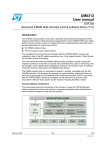
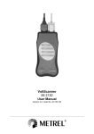
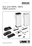
Rotor position/speed feedback
UM1052
Figure 48. 60° and 120° displaced Hall sensor output waveforms
3 sensors 120°
3 sensors 60°
H1
H1
H2
120°
H2
60°
H3
H3
H1
H1
H2
H2
H3
H3
ai14826
Because the rotor position information they provide is absolute, there is no need for any
initial rotor prepositioning. Particular attention must be paid, however, when connecting the
sensors to the proper microcontroller inputs.
This software library assumes that the positive rolling direction is the rolling direction of a
machine that is fed with a three-phase system of positive sequence. In this case, to work
correctly, the software library expects the Hall sensor signal transitions to be in the
sequence shown in Figure 48 for both 60° and 120° displaced Hall sensors.
For these reasons, it is suggested to follow the instructions given below when connecting a
Hall-sensor equipped PM motor to your board:
56/127
1.
Turn the rotor by hand in the direction assumed to be positive and look at the B-emf
induced on the three motor phases. If the real neutral point is not available, it can be
reconstructed by means of three resistors, for instance.
2.
Connect the motor phases to the hardware respecting the positive sequence. Let
“phase A”, “phase B” and “phase C” be the motor phases driven by TIM1_CH1,
TIM1_CH2 and TIM1_CH3, respectively (for example, when using the MB459 board, a
positive sequence of the motor phases could be connected to J5 2,1 and 3).
3.
Turn the rotor by hand in the direction assumed to be positive, look at the three Hall
sensor outputs (H1, H2 and H3) and connect them to the selected timer on channels 1,
2 and 3, respectively, making sure that the sequence shown in Figure 48 is respected.
4.
Measure the delay in electrical degrees between the maximum of the B-emf induced on
phase A and the first rising edge of signal H1. Enter it in the MC_hall_param.h header
file (HALL_PHASE_SHIFT). For your convenience, an example with
HALL_PHASE_SHIFT equal to –90 °C is illustrated in Figure 49.
Doc ID 18458 Rev 3
UM1052
Rotor position/speed feedback
Figure 49. Determination of Hall electrical phase shift
5.3
Encoder sensor feedback processing
Quadrature incremental encoders are widely used to read the rotor position of electric
machines.
As the name implies, incremental encoders actually read angular displacements with
respect to an initial position: if that position is known, then the rotor absolute angle is known
too. For this reason, it is always necessary, when processing the encoder feedback, to
perform a rotor prepositioning before the first startup after any fault event or microcontroller
reset.
Quadrature encoders have two output signals (represented in Figure 50 as TI1 and TI2).
Together with the Root part number 1 standard timer in the encoder interface mode, once
the said alignment procedure has been executed, it is possible to get information about the
actual rotor angle - and therefore the rolling direction - by simply reading the counter of the
timer used to decode encoder signals.
For the purpose of MC Library and as information provided by the MC API, the rotor angle is
expressed in ‘s16degrees’ (see Section 7.4: Measurement units).
Doc ID 18458 Rev 3
57/127
Rotor position/speed feedback
UM1052
Figure 50. Encoder output signals: counter operation
The rotor angular velocity can be easily calculated as a time derivative of the angular
position.
5.3.1
Setting up the system when using an encoder
Extra care should be taken over what is considered to be the positive rolling direction: this
software library assumes that the positive rolling direction is the rolling direction of a
machine that is fed with a three-phase system of positive sequence.
Because of this, and because of how the encoder output signals are wired to the
microcontroller input pins, it is possible to have a sign discrepancy between the real rolling
direction and the direction that is read. To avoid this kind of reading error, apply the following
procedure:
1.
Turn the rotor by hand in the direction assumed to be positive and look at the B-emf
induced on the three motor phases. A neutral point may need to be reconstructed with
three resistors if the real one is not available.
2.
Connect the motor phases to the hardware respecting the positive sequence (for
instance when using the MB459 board, a positive sequence of the motor phases may
be connected to J5 2,1 and 3).
3.
Run the firmware in the encoder configuration and turn by hand the rotor in the
direction assumed to be positive. If the measured speed shown on the LCD is positive,
the connection is correct; otherwise, it can be corrected by simply swapping and
rewiring the encoder output signals.
If this is not practical, a software setting may be modified instead, using the ST MC
Workbench GUI (see the GUI help file).
Alignment settings
The quadrature encoder is a relative position sensor. Considering that absolute information
is required for performing field-oriented control, it is necessary to establish a 0° position.
This task is performed by means of an alignment phase (Section 8.2.3: Configuration and
debug page, callout 9 in Figure 64: Configuration and debug page), and shall be carried out
at the first motor startup and optionally after any fault event. It consists of imposing a stator
flux with a linearly increasing magnitude and a constant orientation.
58/127
Doc ID 18458 Rev 3
UM1052
Rotor position/speed feedback
If properly configured, at the end of this phase, the rotor is locked in a well-known position
and the encoder timer counter is initialized accordingly.
Doc ID 18458 Rev 3
59/127
Working environment
6
UM1052
Working environment
The working environment for the Motor Control SDK is composed of:
●
●
●
●
●
●
A PC
A third-party integrated development environment (IDE)
A third-party C-compiler
A JTAG/SWD interface for debugging and programming
An application board with an STM32F103xx/STM32F100xx, STM32F2xx or
STM32F4xx properly designed to drive its power stage (PWM outputs to gate driver,
ADC channels to read currents, DC bus voltage). Many evaluation boards are available
from ST, some of them have an ST-link programmer onboard.
A three-phase PMSM motor
Table 10 explains the MC SDK file structure for both Web and confidential distributions.
Table 10.
File structure
File
Subfile
MC library
Description
Source file of the MC library layer
interface
Public definitions (interfaces) of classes
inc (available only in
confidential distribution)
Private definitions (data structure) of classes
src (available only in
confidential distribution)
Source files
common
Public definitions (interfaces) of classes and
definitions exported up to the highest level (PI, Digital
Output, reference frame transformation)
obj
Compiled classes
MC Application
Source file of the MC application layer
interface
Public definitions (interfaces) of classes
inc
Private definitions (data structure) of classes
src
Source files
UI library
Source file of the User Interface layer
interface
Public definitions (interfaces) of classes
inc
Private definitions (data structure) of classes
src
Source files
STMFC
LCD graphics library
FreeRTOS source
FreeRTOS V1.6 distribution (GNU GPL license,
http://freertos.org/a00114.html)
CMSIS
Cortex™ Microcontroller Software Interface Standard
v1.30
Libraries
60/127
Doc ID 18458 Rev 3
UM1052
Working environment
Table 10.
File structure (continued)
File
6.1
Subfile
Description
STMF10x_StdPeriph_Driver
STMF10x Standard Peripherals Library Drivers
V3.5.0
STMF2xx_StdPeriph_Driver
STMF2xx Standard Peripherals Library Drivers
V1.0.0
STMF4xx_StdPeriph_Driver
STMF4xx Standard Peripherals Library Drivers
V1.0.0
System &Drive
Params
Contains default parameter files (unpacked at
installation time, referring to the STM32 MC Kit) or
those generated by the ST MC workbench GUI
according to user's system
Utilities
Contains code needed for specific functions of ST
evaluation boards (LCD drivers, I/O pin assignment,
port expanders) and the ST Flash loader
demonstrator V2.2.0.
Project
Contains source files of the demonstration user layer
application and configuration files for IDEs.
In addition, inside each IDE folder (in \MC library
Compiled\exe), compiled MC library is provided (in
case of web distribution) or created/modified by the
IDE (in case of confidential distribution) for single and
dual motor drive.
FreeRTOS
Project
Contains source files of the demonstration user layer
application based on FreeRTOS and configuration
files for IDEs.
In addition, inside each IDE folder (in \MC library
Compiled\exe), compiled MC library is provided (in
case of web distribution) or created/modified by the
IDE (in case of confidential distribution) for single and
dual motor drive.
LCD project
Contains source files of the optional LCD user
interface and configuration files for IDEs
HEX
Contains the compiled version of LCD firmware
ready to be flashed using ST Flash load
EWARM_out
Contains the compiled version of LCD firmware
ready to be flashed using IAR IDE
Motor control workspace
The Motor Control SDK is composed of three projects (as shown in Figure 51), which
constitute the MC workspace.
Doc ID 18458 Rev 3
61/127
Working environment
UM1052
Figure 51. MC workspace structure
The Motor Control Library project: the collection of all the classes (37 among base and
derivative classes) developed to implement all the features. Each class has its own public
interface. A public interface is the list of the parameters needed to identify an 'object' of that
kind and of the methods (or functions) available. Note that, in the case of a derivative class,
applicable methods are those of the specific derived plus those of the base class. Further
detail is provided in the Advanced developers guide for STM32F103xx/STM32F100xx
PMSM single/dual FOC library (UM1053).
All these interfaces constitute the Motor Control Library Interface. The Motor Control Library
project is independent from system parameters (the only exception is single/dual drive
configuration), and is built as a compiled library, not as an executable file (see Section 6.3).
The Motor Control Application project: the application that uses the Motor Control Library
layer. Parameters and configurations related to user's application are used here to create
right objects and rights, in what is called the run-time system 'boot'.
The Motor Control API is the set of commands granted to the upper layer. This project is
built as a compiled library, not as an executable file (see Section 6.4).
The user project: the demonstration program included in the SDK that makes use of the
Motor Control Application through its MC API and provides the required clockings and
access to Interrupt Handlers. The program can run some useful functionalities (depending
on user options), such as serial communication, LCD/keys interface, system variables
displaying through DAC.
5 user project workspaces are available. They differ in both the supported STM32 family and
how they generate the clocks: a simple time base itself or an Operating System, FreeRTOS.
●
●
●
●
●
STM32F10x_Workspace for both STM32F100xx and STM32F103xx devices and
simple time base
STM32F2xx_Workspace for STM32F2xx devices and simple time base
STM32F4xx_Workspace for STM32F4xx devices and simple time base
STM32F10x_RTOS_Workspace for both STM32F100xx and STM32F103xx devices
and FreeRTOS
STM32F2xx_RTOS_Workspace for STM32F2xx devices and FreeRTOS
See Section 7.3: How to create a user project that interacts with the MC API to understand
how to create a brand new user project.
62/127
Doc ID 18458 Rev 3
UM1052
Working environment
In Section 6.5, built .lib files are linked with the user project in order to generate the file that
can be downloaded into the microcontroller memory for execution.
Figure 52 provides an overview of the IAR EWARM IDE workspace (located in the
Installation folder \Project\EWARM\STM32F10x_Workspace.eww) configured for dual
FOC drive. The following sections provide details on this. The equivalent workspace based
on FreeRTOS is located in the Installation folder
\FreeRTOS Project\EWARM\STM32F10x_RTOS_Workspace.eww.
Figure 52. Workspace overview
Section 6.2: MC SDK customization process provides the procedure for customizing the
Motor Control SDK.
6.2
MC SDK customization process
This section explains how to customize the Motor Control SDK using IAR EWARM IDE, so
that it corresponds to the user's current system.
1.
Using the ST MC Workbench GUI, enter the page information to reflect the system
configuration and parameters. This part of the process ends by generating the .h
parameters in the correct directory (Installation folder\System & Drive
Params).
2.
If the system is configured to enable the LCD User Interface, download the specific
firmware. See Section 6.6: LCD UI project.
Doc ID 18458 Rev 3
63/127
Working environment
3.
UM1052
Open one of the MC workspaces:
–
4.
FreeRTOS based:
Installation folder\FreeRTOS Project\EWARM\STM32F10x_RTOS_Workspace.eww
Installation folder\FreeRTOS Project\EWARM\STM32F2xx_RTOS_Workspace.eww
–
Non-FreeRTOS:
Installation folder\Project\EWARM\STM32F10x_Workspace.eww
Installation folder\Project\EWARM\STM32F2xx_Workspace.eww
Installation folder\Project\EWARM\STM32F4xx_Workspace.eww
Enable the user project (callout 1 in Figure 56: User project) and select the appropriate
option from the combo-box (callout 2 in Figure 56: User project). If none of the boards
displayed is in use, read Section 6.5: User project to perform a correct configuration.
5.
Press F8 to batch-build the entire workspace. The dialog box shown in Figure 53:
Workspace batch build appears.
6.
Select a batch command (callout 1, Figure 53) as for step 4, then click the Make button
to make the build (callout 2, Figure 53). If no error or relevant warning appears,
download the firmware (callout 3, Figure 53) and do a test run.
Figure 53. Workspace batch build
Note:
When the system configuration or parameters are modified, it may be necessary to rebuild
either all three projects or just one. The batch command conveniently builds all three, to
avoid problems. This method is not time-consuming, from the compiler point of view,
because if a project is not affected by the modification, it is not recompiled.
Then, usually after having run tests on the motor or found a fine tune, the procedure
required to change drive parameters, re-build and flash the firmware again is shorter: only
steps 1,5,6 need to be done. It's thus suggested that ST MC Workbench GUI and IDE are
left open.
The following sections provide more information about each of the three projects of the MC
workspace.
64/127
Doc ID 18458 Rev 3
UM1052
6.3
Working environment
Motor control library project (confidential distribution)
The MC Library project (available only in confidential distribution) is a collection of classes
related to motor control functionalities.
1.
To access the project using IAR IDE, open an MC workspace (FreeRTOS based or not)
and click the name in the workspace tabbed browser (callout1, Figure 54). Remember
that IDE toolbars and commands always refer to the active project (the one whose tab
is engraved).
Figure 54 displays the logical arrangement of files on the left-hand side (similar
arrangement is in folders). For each class, the MC Library subfolder src contains the
source code, private contains its private definitions, interface contains its public
interface, obj contains compiled object files of certain classes.
Figure 54. MC Library project
2.
Depending on system characteristics, configure the project for single motor drive or
dual motor drive by selecting SINGLE_DRIVE or DUAL_DRIVE from the combo-box
(callout 2, Figure 54).
3.
Classes of the MC Library can create new objects resorting to dynamic memory
allocation, or statically allotting them from predefined size-pools. This is a matter of
preference. Modify the header file MCLibraryConf.h to choose the allocation (callout 3,
Figure 54). To activate the dynamic allocation, uncomment line 45 (#define
MC_CLASS_DYNAMIC). To activate the static allocation, comment this line.
4.
Once all these settings have been configured and checked, build the library (callout 4,
Figure 54).
If SINGLE_DRIVE was selected, the proper output file among the following:
- MC_Library_STM32F10x_single_drive.a
- MC_Library_STM32F2xx_single_drive.a
- MC_Library_STM32F4xx_single_drive.a
is created in Installation folder \Project\EWARM\MC Library
Compiled\Exe or Installation folder \FreeRTOS Project\EWARM\MC
Library Compiled\Exe.
Doc ID 18458 Rev 3
65/127
Working environment
UM1052
If DUAL_DRIVE was selected, the proper output file among the following:
- MC_Library_STM32F10x_dual_drive.a
- MC_Library_STM32F2xx_dual_drive.a
- MC_Library_STM32F4xx_dual_drive.a
is created in Installation folder \Project\EWARM\MC Library
Compiled\Exe or Installation folder \FreeRTOS Project \EWARM\MC
Library Compiled\Exe.
5.
6.4
Compliancy with MISRA-C rules 2004 can be checked using IAR EWARM. The test is
performed by uncommenting line 35 (#define MISRA_C_2004_BUILD) in the header
file Installation folder \MC Library\Interface\Common\MC_type.h. The
compiler should be configured in Strict ISO/ANSI standard C mode (MISRA C 2004
rule 1.1).
Motor control application project
As explained in previous sections, the Motor Control Application project is the Motor Control
application program.
1.
Access the project using IAR IDE by opening an MC workspace (FreeRTOS based or
not), and clicking its name in the workspace tabbed browser (callout 1, Figure 55). IDE
toolbars and commands always refer to the active project (the one whose tab is
engraved).
Figure 55 displays the logical arrangement of files (a similar arrangement is in folders).
Figure 55. Motor control application project
Project source files are arranged in the logical folder MC Application.
66/127
Doc ID 18458 Rev 3
UM1052
Working environment
The MC Library Interface folder contains all the interfaces of each class belonging to
the MC Library.
The System and Drive Parameters folder contains the header files that should be filled
in so as to describe characteristics and parameters of the user's system.
6.5
2.
To adjust system and drive parameters (callout 2, Figure 55), separately for Motor 1
and Motor 2, edit the header files manually or generate them using the ST MC
Workbench GUI. The header file SystemNDriveParams.h arranges all these
parameters in the form of constant structures for object initialization, so that the MC
Application can create the controls required during the initial run-time boot.
3.
After these settings have been performed, build the Motor Control Interface (callout 3,
Figure 55). The proper output file among the following:
MC_Application_STM32F10x.a
MC_Application_STM32F2xx.a
MC_Application_STM32F4xx.a,
is created in Installation folder\Project\EWARM\MC Application
Compiled\Exe or Installation folder\FreeRTOS Project \EWARM\MC
Application Compiled\Exe.
User project
The User project is the application layer that exploits the MC API.
1.
Access the project using IAR IDE by opening an MC workspace (FreeRTOS based or
not), and clicking its name in the workspace tabbed browser (callout 1, Figure 56).
Remember that IDE toolbars and commands always refer to the active project (the one
whose tab is engraved).
Doc ID 18458 Rev 3
67/127
Working environment
UM1052
Figure 56 displays the logical arrangement of files and actions necessary to set up and
download the User project.
Figure 56. User project
The Motor Control folder contains the MC API and interfaces of classes that may also be
useful in the user's application (such as PI, Digital Output, reference frame transformation).
The Std project template folder contains:
●
●
●
STM32Fxxx Standard Peripherals Library
CMSIS library, startup and vector table files for EWARMv5 toolchain
IC drivers (LCD, IOE, SD card) used in STM32 evaluation boards.
All these files belong to V3.5.0 distribution of the STM32 Standard Peripheral Library
package for the STM32F10x and to v1.0.0 distribution for STM32F2xx and STM32F4xx
(updates available from STMicroelectronics web site, www.st.com).
This demonstration user project exploits the features offered by the User Interface Library
(see Section 9: User Interface class overview for further details).
In the STM32F10x_Workspace, four project configurations (callout 2, Figure 56: User
project) are provided, one for each STM32 evaluation board that has been tested with the
MC SDK:
●
●
●
●
STM32F10B-EVAL
STM32F10E-EVAL
STM32F100B-EVAL
STEVAL-IHM022V1
In the STM32F2xx_Workspace, two project configurations are available:
●
68/127
STM322xG-EVAL
Doc ID 18458 Rev 3
UM1052
Working environment
●
STM32F2xx_dual
In the STM32F4xx_Workspace, two project configurations are available:
●
●
STM324xG-EVAL
STEVAL-IHM039V1
If the target is one of these boards, just select its name from the combo-box. Otherwise, the
LCD UI should be disabled (using the ST MC Workbench GUI) and the choice is to be done
according to Table 11:
Table 11.
Project configurations
STM32 device part, single/dual drive
selection
Viable configuration among existing
STM32F103 low density/medium density
STM32F10B-EVAL
STM32F103 high density/XL density, Single
motor drive
STM32F10E-EVAL
STM32F103 high density/XL density, Dual motor
STEVAL-IHM022V1
drive
STM32F100 low / medium / high density
STM32F100B-EVAL
STM32F2xx, Single motor drive
STM322xG-EVAL
STM32F2xx, Dual motor drive
STM32F2xx_dual
STM32F4xx, Single motor drive
STM324xG-EVAL
STM32F4xx, Dual motor drive
STEVAL-IHM039V1
If the target is not one of the above-mentioned ST evaluation boards, or if you want to modify
the configurations provided, right-click on User Project (callout 3, Figure 56) > Option to
open the Options dialog box. Select the correct device part number (callout 4, Figure 56)
and edit the linker file (callout 5, Figure 56).
Note:
MC SDK default linker files reserve an amount of Flash and RAM (heap) for LCD UI
manager (see Section 6.5). We recommend that you restore their total size (please refer to
the STM32 datasheet) if you do not need it.
Once all these settings have been performed, the MC Library and MC Application projects
are built and you can build the user project (callout 6, Figure 56), and download it to the
microcontroller memory (callout 7, Figure 56).
6.6
LCD UI project
When an STM32 evaluation board equipped with LCD (such as STM3210B-EVAL,
STM3210E-EVAL, STM32100B-EVAL, STEVAL-IHM022V1, STM322xG-EVAL, STM324xGEVAL, STEVAL-IHM039V1) is in use, you can enable the LCD plus Joystick User Interface—
a useful feature of the demonstration user project that can be used as a run-time command
launcher, a fine-tuning or monitoring tool (screens and functionalities are detailed in
Section 8). This option can be selected via a setting in the ST MC Workbench GUI (see
Section 6.2).
In this case, the LCD UI software (single or dual drive configuration) is downloaded in the
microcontroller in a reserved area, located at the end of the addressable Flash memory.
Doc ID 18458 Rev 3
69/127
Working environment
UM1052
Unless you erase it or change the configuration from single-drive to dual-drive or vice-versa,
there is no need to download it again. Even disabling the option with the GUI does not mean
you need to flash it again when you reenable the option.
The latest STM3210B-MCKIT Motor Control starter kits come with the Motor Control Library
and the LCD UI software (single-drive) pre-flashed. If your Motor Control kit has a version of
Motor Control Library lower than 3.0, or if you do not have the Motor Control kit but you are
using one of the evaluation boards mentioned, or if you are changing the configuration
(single-dual), you should follow one of the three procedures explained below to download
the LCD UI.
Option 1
Option 1 is straightforward and the preferred one.
1. Use the IAR Embedded Workbench IDE to download the LCD pre-compiled file opening
the proper MC workspaces as explained in section 6.1
2. Select the proper User project as explained in section 6.5
3. Activate Project->Download->Download file... in the IAR menu
4. Select the appropriate pre-compiled file (STM3210B-EVAL.out, STM32100B-EVAL.out,
STM3210E-EVAL.out, STEVAL-IHM022V1.out, STM322xG-EVAL.out,
STM32F2xx_dual.out, STM324xG-EVAL.out, STM32F4xx_dual.out)
Option 2
1.
Use the STM32 and STM8 Flash loader demonstrator PC software package. This is
available from the ST web site
(http://www.st.com/internet/com/SOFTWARE_RESOURCES/SW_COMPONENT/SW_
DEMO/um0462.zip) and in the \Installation folder\Utilities\Flash loader\.)
The User Manual, UM0462 (included in the package), fully explains how to operate it.
For communication purposes, you need to verify that you have an available COM port
(RS232) on your PC.
70/127
2.
After the program is installed, run the Flash loader demonstrator application from the
Programs menu, making sure that the device is connected to your PC and that the boot
configuration pins are set correctly to boot from the system memory (check the
evaluation board user manual).
3.
Reset the microcontroller to restart the system memory boot loader code.
4.
When the connection is established, the wizard displays the available device
information such as the target ID, the firmware version, the supported device, the
memory map and the memory protection status. Select the target name in the target
combo-box.
5.
Click the Download to device radio button (see Figure 57) and browse to select the
appropriate hexadecimal file (STM3210B-EVAL.hex, STM32100B-EVAL.hex,
STM3210E-EVAL.hex, STEVAL-IHM022V1.hex, STM322xG-EVAL.hex
STM32F2xx_dual.hex, STM324xG-EVAL.hex, STM32F4xx_dual.hex) from Installation
folder\LCD Project\Hex\.
6.
Program the downloading to Flash memory. After the code has been successfully
flashed, set up the board to reboot from the user Flash memory and reset the
microcontroller.
Doc ID 18458 Rev 3
UM1052
Working environment
7.
To test that the LCD UI has been correctly flashed, for both option 1 and 2, open, build
and download the user project (see Section 6.2: MC SDK customization process and
Section 6.5: User project).
8.
From the debug session, run the firmware (F5) and then, after a while, stop debugging
(CTRL+Shift+D). The LCD UI has not been properly flashed if the program is stalled in
a trap inside UITask.c, line 133.
Figure 57. Flash loader wizard screen
Option 3
This option is intended for users who want to modify the LCD UI code.
1.
Use an IDE to rebuild and download the LCD UI.
2.
After parameter files have been generated by the GUI (to set the single/dual drive
configuration) using IAR EWARM IDE V6.30, open the workspace located in
Installation folder\LCD Project\EWARM\UI Project.eww.
Doc ID 18458 Rev 3
71/127
Working environment
UM1052
Figure 58. LCD UI project
Figure 58 displays the logical arrangement of files (left-hand side) and actions that may
be needed for set-up and download.
Three project configurations are provided for the STM32F10x_Workspace (callout 1,
Figure 58), one for each STM32 evaluation board that has been tested with the MC
SDK:
–
STM32F10B-EVAL
–
STM32F10E-EVAL
–
STEVAL-IHM022V1
Two projects configurations are provided for the STM32F2xx_Workspace:
–
STM322xG-EVAL
–
STM32F2xx_dual
Two projects configurations are provided for the STM32F4xx_Workspace:
–
–
Note:
STM324xG-EVAL
STEVAL-IHM039V1
To download the LCD firmware for STM32F100B-EVAL, please use option 1 or option 2.
This configuration affects the LCD driver and linker file selection.
72/127
3.
Build the project (callout 2, Figure 58), and download it to the microcontroller memory
(callout 3, Figure 58).
4.
To test that the LCD UI has been correctly flashed, for both option 1 and 2, open, build
and download the user project (see Section 6.2: MC SDK customization process and
Section 6.5: User project).
5.
From the debug session, run the firmware (F5) and then, after a while, stop debugging
(CTRL+Shift+D). The LCD UI has not been properly flashed if the program is stalled in
a trap in UITask.c, line 133.
Doc ID 18458 Rev 3
UM1052
7
MC application programming interface (API)
The Motor Control Application is built on top of the Motor Control Library, provided that:
●
●
parameter files are generated by the ST MC workbench GUI, or manually edited
starting from default, for the purpose of describing the system configuration;
a user project, such as the one included in the SDK, or any other one that complies
with the guidelines described in Section 7.3: How to create a user project that interacts
with the MC API, is in place.
The MCA grants the user layer the execution of a set of commands, named the MC
Application Programming Interface (MC API).
The MC API is divided into two sections and is included in two files: MCInterfaceClass.h and
MCTuningClass.h. MCInterfaceClass (details in Section 7.1) holds the principal high-level
commands, while MCTuningClass (details in Section 7.2) acts as a gateway to set and read
data to and from objects (such as sensors, PI controllers) belonging to the Motor Control
Application.
A third section belongs to MC API, MCtask.h: it holds the MCboot function and tasks
(low/medium/high frequency and safety) to be clocked by the user project (see Section 7.3:
How to create a user project that interacts with the MC API for details)
When the user project calls function MCboot (oMCI, oMCT), the Motor Control Application
starts its operations: the booting process begins, objects are created from the Motor Control
Library according to the system configuration (specified in parameter files), and the
application is up and represented by two objects, oMCI and oMCT, whose type is
respectively CMCI and CMCT (type definition can be obtained by including
MCInterfaceClass.h and MCTuningClass.h). Methods of MCInterfaceClass must be
addressed to the oMCI object, oMCT addresses methods of MCTuningClass. oMCI and
oMCT are two arrays, each of two elements, so that oMCI[0] and oMCT[0] refer to Motor 1,
oMCI[1] and oMCT[1] refer to Motor2.
GetMCIList function, to be called if necessary after MCboot, returns a pointer to the CMCI
oMCI vector instantiated by MCboot. The vector has a length equal to the number of motor
drives.
GetMCTList function, to be called if necessary after MCboot, returns a pointer to the CMCT
oMCT vector instantiated by MCboot. The vector has a length equal to the number of motor
drives.
7.1
MCInterfaceClass
Commands of the MCInterfaceClass can be grouped in two different typologies:
●
●
User commands: commands that become active as soon as they are called. If the state
machine is not in the expected state, the command is discarded and the method
returns FALSE. The user must manage this by resending the command until it is
accepted, or by discarding the command.
Buffered commands: commands that do not execute instantaneously, but are stored in
a buffer and become active when the state machine is in a specified state. These
commands are not discarded until they become active, unless other delayed
commands are sent to the buffer, thus clearing the previous one.
Doc ID 18458 Rev 3
73/127
MC application programming interface (API)
UM1052
Detailed information can be found in the Motor Control Application source documentation
(doxygen compiled .html Help file).
7.1.1
User commands
●
●
●
●
●
bool MCI_StartMotor(CMCI oMCI): starts the motor. It is mandatory to set the
target control mode (speed control/torque control) and initial reference before executing
this command, otherwise the behavior in run state is unpredictable. Use one of these
commands to do this: MCI_ExecSpeedRamp, MCI_ExecTorqueRamp or
MCI_SetCurrentReferences.
bool MCI_StopMotor(CMCI oMCI): stops the motor driving and disables the PWM
outputs.
bool MCI_FaultAcknowledged(CMCI oMCI): this function must be called after a
system fault to tell the Motor Control Interface that the user has acknowledged the
occurred fault. When a malfunction (overcurrent, overvoltage) is detected by the
application, the motor is stopped and the internal state machine goes to the Fault state
(see Figure 59). The API is locked (it no longer receives commands). The API is
unlocked and the state machine returns to Idle when the user sends this
MCI_FaultAcknowledged.
bool MCI_EncoderAlign(CMCI oMCI): this function is only used when an encoder
speed sensor is used. It must be called after any system reset and before the first
motor start.
State_t MCI_GetSTMState(CMCI oMCI): returns the state machine status (see
Figure 59). Further detail is provided in the Advanced developers guide for
STM32F103xx/STM32F100xx PMSM single/dual FOC library (UM1053).
Figure 59. State machine flow diagram
●
74/127
int16_t MCI_GetMecSpeedRef01Hz(CMCI oMCI): returns the current
mechanical rotor speed reference expressed in tenths of Hertz.
Doc ID 18458 Rev 3
UM1052
MC application programming interface (API)
●
●
●
int16_t MCI_GetTorque(CMCI oMCI): returns the present motor measured
torque. This value represents the Iq current expressed in 's16A'. To convert a current
expressed in 's16A' to current expressed in Ampere, use the formula:
Current[A] = [Current(s16A) * Vdd micro(V)] / [65536 *
Rshunt(Ohm) * AmplificationNetworkGain]
●
Curr_Components MCI_GetCurrentsReference(CMCI oMCI): returns stator
current references Iq and Id in 's16A'. To convert a current expressed in 's16A' to a
current expressed in Ampere, use the formula:
Current[A] = [Current(s16A) * Vdd micro(V)] / [65536 *
Rshunt(Ohm) * AmplificationNetworkGain].
●
int16_t MCI_GetPhaseCurrentAmplitude(CMCI oMCI): returns the motor
phase current amplitude (0-to-peak) in 's16A'. To convert a current expressed in 's16A'
to a current expressed in Ampere, use the formula:
Current[A] = [Current(s16A) * Vdd micro(V)] / [65536 *
Rshunt(Ohm) * AmplificationNetworkGain].
●
int16_t MCI_GetPhaseVoltageAmplitude(CMCI oMCI): returns the applied
motor phase voltage amplitude (0-to-peak) in 's16V'. To convert a voltage expressed in
's16V' to a voltage expressed in Volt, use the formula:
PhaseVoltage(V) = [PhaseVoltage(s16V) * Vbus(V)] /[sqrt(3)
*32767].
●
STC_Modality_t MCI_GetControlMode(CMCI oMCI): returns the present
control mode: speed mode or torque mode.
int16_t MCI_GetImposedMotorDirection(CMCI oMCI): returns the motor
direction imposed by the last command (MCI_ExecSpeedRamp,
MCI_ExecTorqueRamp or MCI_SetCurrentReferences).
int16_t MCI_GetLastRampFinalSpeed (CMCI this): returns information
about the last ramp final speed sent by the user, expressed in tenths of HZ.
●
●
7.1.2
int16_t MCI_GetAvrgMecSpeed01Hz(CMCI oMCI): returns the last computed
average mechanical speed expressed in tenth of Hertz.
int16_t MCI_GetTorqueRef(CMCI oMCI): returns the present motor torque
reference. This value represents the Iq current reference expressed in 's16A'. To
convert a current expressed in 's16A' to a current expressed in Ampere, use the
formula:
Current[A] = [Current(s16A) * Vdd micro(V)] / [65536 *
Rshunt(Ohm) * AmplificationNetworkGain]
Buffered commands
●
●
void MCI_ExecSpeedRamp(CMCI oMCI, int16_t hFinalSpeed, uint16_t
hDurationms): sets the control mode in speed control, generates a ramp of speed
references from real speed to hFinalSpeed parameter (to be expressed as mechanical
rotor speed, tenth of hertz). The ramp execution duration is the ‘hDurationms’
parameter (to be expressed in milliseconds). If hDurationms is set to 0, a step variation
is generated. This command is only executed when the state machine is in the
START_RUN or RUN state. The user can check the status of the command calling the
MCI_IsCommandAcknowledged method.
void MCI_ExecTorqueRamp(CMCI oMCI, int16_t hFinalTorque,
uint16_t hDurationms): sets the control mode in "torque control", generates a
ramp of torque references from real torque to the ‘hFinalTorque’ parameter (to be
expressed as s16A). The ramp execution duration is the hDurationms parameter (to be
Doc ID 18458 Rev 3
75/127
MC application programming interface (API)
●
●
7.2
UM1052
expressed in milliseconds). If hDurationms is set to 0, a step variation is generated.
This command is only executed when the state machine is in the START_RUN or RUN
state. The user can check the status of the command calling the
MCI_IsCommandAcknowledged method.
void MCI_SetCurrentReferences(CMCI oMCI, Curr_Components
Iqdref): sets the control mode in "torque control external" (see Advanced developers
guide for STM32F103xx/STM32F100xx PMSM single/dual FOC library (UM1053)) and
directly sets the motor current references Iq and Id (to be expressed as s16A). This
command is only executed when the state machine status is START_RUN or RUN.
CommandState_t MCI_IsCommandAcknowledged(CMCI oMCI): returns
information about the state of the last buffered command. CommandState_t can be one
of the following codes:
–
MCI_BUFFER_EMPTY if no buffered command has been called.
–
MCI_COMMAND_NOT_ALREADY_EXECUTED if the buffered command condition
has not already occurred.
–
MCI_COMMAND_EXECUTED_SUCCESFULLY if the buffered command has been
executed successfully. In this case, calling this function resets the command state
to MCI_BUFFER_EMPTY.
–
MCI_COMMAND_EXECUTED_UNSUCCESFULLY if the buffered command has been
executed unsuccessfully. In this case, calling this function resets the command
state to MCI_BUFFER_EMPTY.
MCTuningClass
The MCTuningClass allows the user to obtain objects of the Motor Control Application and
apply methods on them.
MCTuningClass.h is divided into three sections:
●
●
●
Public definitions of all the MC classes exported
MCT_GetXXX functions, used to receive objects
For each of the classes exported, a list of applicable methods
For example, if you want to read or set parameters of the speed PI controller:
1.
Make sure that the Motor Control Application is already booted, and oMCI and oMCT
objects are available (you can receive them through GetMCIList or GetMCTList
functions)
2.
Declare a 'PIspeed' automatic variable of the type CPI (PI class, type definition at line
85)
3.
Obtain the speed PI object (which is actually a pointer) by calling the
MCT_GetSpeedLoopPID function (prototype at line 203)
4.
Set the KP gain by calling the PI_SetKP function (prototype at line 659).
The resulting C code could be something like:
#include "MCTuningClass.h"
{
...
CPI PIspeedMotor2;
...
PIspeedMotor2 = MCT_GetSpeedLoopPID(oMCT[1]);
76/127
Doc ID 18458 Rev 3
UM1052
MC application programming interface (API)
PI_SetKP(PIspeedMotor2, NewKpGain);
...
}
Note:
7.3
1
To reduce Flash and RAM occupation, you can disable the MCTuning section of the MC
application. This is done by commenting #define MC_TUNING_INTERFACE in the
MCTask.c source file, line 80. If you do this, disable the LCD UI and Serial Communication
UI too.
2
See the doxygen compiled .html Help file to know which are the other exported functions of
MCTasks and refer to section 7.3 to know how to use them.
How to create a user project that interacts with the MC API
This section explains how to integrate the Motor Control Application with a user project (thus
replacing the provided demonstrative one) in order to take advantage of its API.
1.
A timebase is needed to clock the MC Application: the demonstration timebase.c can
be considered as an example or used as is. It uses the Systick timer and its
Systick_Handler and PendSV_Handler as resources.
Alternatively, an Operating System can be used for this purpose, as is done in the
FreeRTOS-based demonstration project.
The timebase should provide the clocks listed in Table 12:
Table 12.
Number
2.
Note:
Integrating the MC Interface in a user project
Function to call
Periodicity
Priority
Preemptiveness
*1
TSK_LowFrequencyTask
10 ms
Base
Yes, over non MC
functions.
*2
TSK_MediumFrequencyTa
sk
Equal to that set in
ST MC Workbench,
speed regulation
rate
Higher than *1
Yes, over *1
*3
TSK_SafetyTask
0.5 ms
Higher than *2
Yes, over *1,
(optional over *2)
include source files:
In the following code, $ stands for Installation Folder.
For STM32F1xx projects
$\Libraries\CMSIS\CM3\DeviceSupport\ST\STM32F10x\system_stm32f1
0x.c
$\Libraries\CMSIS\CM3\DeviceSupport\ST\STM32F10x\startup\XXX\st
artup_stm32f10x_YYY.s (XXX according to IDE)(YYY according to
device)
$\Project\stm32f10x_it.c (removing conditional compilation, can
be modified) $\Project\System & Drive Params\stm32f10x_MC_it.c
(GUI generated according to system parameters)
$\Libraries\STM32F10x_StdPeriph_Driver\src\ (standard peripheral
driver sources as needed)
Doc ID 18458 Rev 3
77/127
MC application programming interface (API)
UM1052
for STM32F2xx projects
$\Libraries\CMSIS\CM3\DeviceSupport\ST\STM32F2xx\system_stm32f2
xx.c
$\Libraries\CMSIS\CM3\DeviceSupport\ST\STM32F2xx\startup\XXX\st
artup_stm32f2xx.s (XXX according to IDE)
$\Project\stm32f2xx_it.c (removing conditional compilation, can
be modified)
$\Project\System & Drive Params\stm32f2xx_MC_it.c (GUI generated
according to system parameters)
$\Libraries\STM32F2xx_StdPeriph_Driver\src\
peripheral driver sources as needed)
(standard
for STM32F4xx projects
$\Libraries\CMSIS\CMSIS_2_x\Device\ST\STM32F4xx\Source\Template
ssystem_stm32f4xx.c
$\Libraries\CMSIS\CMSIS_2_x\Device\ST\STM32F4xx\Source\Template
s\XXX\startup_stm32f4xx.s (XXX according to IDE)
$\Project\stm32f4xx_it.c (removing conditional compilation, can
be modified)
$\Project\System & Drive Params\stm32f4xx_MC_it.c (GUI generated
according to system parameters)
$\Libraries\STM32F4xx_StdPeriph_Driver\src\ (standard peripheral
driver sources as needed)
3.
Note:
include paths:
In the following code, $ stands for Installation Folder.
for STM32F1xx projects
$\Libraries\CMSIS\CM3\DeviceSupport\ST\STM32F10x\
$\Libraries\STM32F10x_StdPeriph_Driver\inc\
$\MC library\interface\common\
$\MC Application\interface\
$\System & Drive Params\
$\Project\
for STM32F2xx projects
$\Libraries\CMSIS\CM3\DeviceSupport\ST\STM32F2xx
$\Libraries\STM32F2xx_StdPeriph_Driver\inc
$\MC library\interface\common\
$\MC Application\interface\
$\System & Drive Params\
$\Project\
78/127
Doc ID 18458 Rev 3
UM1052
MC application programming interface (API)
for STM32F4xx projects
$\Libraries\CMSIS\CMSIS_2_x\Device\ST\STM32F4xx\Include
$\Libraries\STM32F4xx_StdPeriph_Driver\inc
$\MC library\interface\common\
$\MC Application\interface\
$\System & Drive Params\
$\Project\
4.
include libraries:
(if in single motor drive) Select the proper libraries according
to the microcontroller family:
*\MC Library Compiled\Exe\MC_Library_STM32F10x_single_drive.a
*\MC Library Compiled\Exe\MC_Library_STM32F2xx_single_drive.a
*\MC Library Compiled\Exe\MC_Library_STM32F4xx_single_drive.a
(if in dual motor drive) Select the proper libraries according
to the microcontroller family:
*\MC Library Compiled\Exe\MC_Library_STM32F10x_dual_drive.a
*\MC Library Compiled\Exe\MC_Library_STM32F2xx_dual_drive.a
*\MC Library Compiled\Exe\MC_Library_STM32F4xx_dual_drive.a
Select the proper libraries according to the microcontroller
family:
**\MC Application Compiled\Exe\MC_Application_STM32F10x.a
**\MC Application Compiled\Exe\MC_Application_STM32F2xx.a
**\MC Application Compiled\Exe\MC_Application_STM32F4xx.a
* is the path where the MC Library IDE project is located
** is the path where the MC Application IDE project is located
5.
define symbols:
USE_STDPERIPH_DRIVER
STM32F10X_MD \ STM32F10X_HD \ STM32F10X_MD_VL \ STM32F2XX,
STM32F40X(according to STM32 part)
6.
Set the STM32 NVIC (Nested Vectored Interrupt Controller) priority group configuration
(the default option is NVIC_PriorityGroup_3).
NVIC_PriorityGroupConfig(NVIC_PriorityGroup_3);
Table 13 shows preemption priorities used by the MC application; user priorities should
be lower (higher number):
Doc ID 18458 Rev 3
79/127
MC application programming interface (API)
Table 13.
UM1052
MC application preemption priorities
IRQ
Preemption priority
TIM1 UPDATE
0
TIM8 UPDATE (F103HD/XL, F2xx, F4xx)
0
DMA
0
ADC1_2 (F103, F2xx, F4xx)
2
ADC3 (F103HD/XL, F2xx, F4xx)
2
ADC1 (F100 only)
2
USART (UI library)
3
TIMx GLOBAL (speed sensor decoding)
3
Timebase
>3
Table 14.
Priority configuration, overall (non FreeRTOS)
Component
Preemption priority
MC Library
0,1,2,3
Timebase (MCA clocks)
3,4
User
5,6,7
Table 15.
Priority configuration, overall (FreeRTOS)
Component
Preemption priority
MC Library
0,1,2,3
User (only FreeRTOS API)
4,5
FreeRTOS
6,7
RTOS priority
MCA clock tasks
Highest
User tasks
Lower
7.
Include the Motor Control Interface in the source files where the API is to be accessed:
#include "MCTuningClass.h"
#include "MCInterfaceClass.h"
#include "MCTasks.h"
8.
Declare a static array of CMCI (MC Interface class) type:
CMCI oMCI[MC_NUM]; /* MC_NUM is the number of motors to drive*/
9.
Declare a static array of CMCT (MC Tuning class) type:
CMCT oMCT[MC_NUM]; /* MC_NUM is the number of motors to drive*/
10. Start the MC Interface boot process:
MCboot(oMCI,oMCT);
80/127
Doc ID 18458 Rev 3
UM1052
MC application programming interface (API)
11. Send the command to the MC API. For example:
MCI_ExecSpeedRamp(oMCI[1],100,1000);
MCI_StartMotor(oMCI[1]);
... /* after a laps of time*/
MCI_StopMotor(oMCI[1]);
7.4
Measurement units
7.4.1
Rotor angle
The rotor angle measurement unit used in the MC API has been named 's16degrees', being
2π 1s16degree = --------------65536
The picture below shows how an angle expressed in radians can be mapped into the
s16degrees domain.
Figure 60. Radians vs s16
7.4.2
Rotor speed
The rotor speed units used in the MC API are:
●
●
Tenth of Hertz (01Hz): straightforwardly, it is 01Hz = 0.1 Hz
digit per control period (dpp): the dpp format expresses the angular speed as the
variation of the electrical angle (expressed in s16 format) within a FOC period,
1s16degree
1dpp = ----------------------------------1FOCperiod
Doc ID 18458 Rev 3
81/127
MC application programming interface (API)
UM1052
An angular speed, expressed as the frequency in Tenth of Hertz (01Hz), can be easily
converted to dpp using the formula:
65536
ωdpp = ω01Hz • -------------------------------------------10 • FOCfreq Hz
7.4.3
Current measurement
Phase currents measurement unit used in the MC API has been named 's16A', being:
MaxMeasureableCurrent
1s16A = ---------------------------------------------------------------------------A32767
A current, expressed in Ampere, can be easily converted to s16A, using the formula:
i A × 65536 • RShunt Ω × AmplificationGain
i s16A = ---------------------------------------------------------------------------------------------------------------------µC_VDD v
7.4.4
Voltage measurement
Applied phase voltage unit used in the MC API has been named 's16V', being:
MaxApplicablePhaseVoltage
1s16V = ---------------------------------------------------------------------------------------V32767
82/127
Doc ID 18458 Rev 3
UM1052
LCD user interface
8
LCD user interface
8.1
Running the motor control firmware using the LCD interface
The STM32 motor control library (V3.2) includes a demonstration program that enables you
to display drive variables, customize the application by changing parameters, and enable
and disable options in real time.
The user interface reference is the one present in the STM32 evaluation boards and is
shown in Figure 61.
Figure 61. User interface reference
The interface is composed of:
●
●
●
A 320x240 pixel color LCD screen
A joystick (see Table 16 for the list of joystick actions and conventions)
A push-button (KEY button)
Table 16.
Joystick actions and conventions
Keyword
User action
UP
Joystick pressed up
DOWN
Joystick pressed down
LEFT
Joystick pressed to the left
RIGHT
Joystick pressed to the right
JOYSEL
Joystick pushed
KEY
Press the KEY push-button
Doc ID 18458 Rev 3
83/127
LCD user interface
UM1052
In the default firmware configuration, the LCD management is enabled. It can be disabled
using the STM32 MC Workbench or disabling the feature and manually changing the line:
define #define LCD_JOYSTICK_BUTTON_FUNCTIONALITY DISABLE (line 316) of
the Drive parameters.h file.
The LCD management is provided by a separate workspace (UI Project) that should be
compiled and programmed before the motor control firmware programming.
8.2
LCD User interface structure
The demonstration program is based on circular navigation pages.
Figure 62 shows the page structure. The visibility of certain pages shown in Figure 62
depends on the firmware configuration:
●
●
●
●
Dual control panel is only present if the firmware is configured for dual motor drive.
Speed controller page is only present when the firmware is configured in speed mode.
Sensorless tuning page (PLL) is only present if the firmware is configured with state
observer with PLL as primary or auxiliary speed sensor.
Sensorless tuning page (CORDIC) is only present if the firmware is configured with
state observer with CORDIC as primary or auxiliary speed sensor.
To navigate the help menus, use:
●
●
RIGHT to navigate to the next page on the right
LEFT to navigate to the next page on the left
Figure 62. Page structure and navigation
LEFT
WELCOME
HELP PAGE
RIGHT
CONFIG
AND DEBUG
PAGE
DUAL
CONTROL
PANEL
RIGHT
LEFT
SPEED
CONTROLLER
PAGE
RIGHT
LEFT
CURRENT
CONTROLLERS
PAGE
RIGHT
LEFT
SENSORLESS
TUNING PAGE
PLL
RIGHT
LEFT
SENSORLESS
TUNING PAGE
CORDIC
RIGHT
LEFT
RIGHT
LEFT
MS19355V1
Each page is composed of a set of controls. Table 17 presents the list of controls used in the
LCD demonstration program.You can navigate between focusable controls in the page by
pressing the UP and DOWN joystick. The focused control is highlighted with a blue
rectangle. When focused, you can activate the control by pressing JOYSEL.
84/127
Doc ID 18458 Rev 3
UM1052
LCD user interface
Table 17.
List of controls used in the LCD demonstration program
Control name and
Example
Edit box
1500
rpm
Combo-box
Speed
Button
Fault ack
Description
Manages a numerical value. It can be "read-only" or "read/write".
A read-only edit box has a gray background and cannot be focusable. A
read/write edit box has a white background and can be focusable.
When a read/write edit box is focused, it can be activated for modification by
pressing JOYSEL. An activated read/write edit box has a green background
and its value can be modified pressing and/or keeping pressed the UP/DOWN
joystick.
When the UP joystick is kept pressed, the value is increased with a constant
acceleration. When the DOWN joystick is kept pressed, the value is decreased
with a constant acceleration.
The new value is set to the motor control-related object instantaneously when
the value changes, unless otherwise mentioned in this manual. The control
can be deactivated by pressing JOYSEL again.
Manages a list of predefined values. The values associated to a combo-box
are text strings that correspond with different configurations or options of the
firmware.
For example, Speed or Torque control mode. The combo-box is always
focusable and, when focused, can be activated for modification by pressing
JOYSEL.
An activated combo-box has a green background and its value can be
modified by pressing the UP/DOWN joystick. The combo-box values are
circular. Going UP from the first value selects the last value and vice versa.
The new value is set to the motor control-related object instantaneously when
the value changes, unless otherwise mentioned in this manual. The control
can be deactivated by pressing JOYSEL again.
Sends commands to motor control-related object. For example, a start/stop
button. This button can be enabled or disabled.
A disabled button is drawn in light gray and cannot be focusable. An enabled
button is painted in black and can be focusable.
When focused, a button can be activated by pressing JOYSEL. This
corresponds to "pushing" the button and sending the related command.
Check box
Link X
8.2.1
Enables or disables an option. It is always focusable and, when focused, can
be activated by pressing JOYSEL. This corresponds to "check/uncheck" the
control and means "enable/disable" the option.
Motor control application layer configuration (speed sensor)
The motor control application layer can be configured to use a position and speed sensor as
a primary or auxiliary speed sensor.
A primary speed and position sensor is used by the FOC algorithm to drive the motor. It is
mandatory to configure a primary speed sensor.
An auxiliary speed and position sensor may be used in parallel with the primary sensor for
debugging purposes. It is not used by the FOC algorithm. It is not mandatory to configure an
auxiliary speed sensor.
Doc ID 18458 Rev 3
85/127
LCD user interface
UM1052
The following sensors are implemented in the MC library:
●
●
●
●
8.2.2
Hall sensor
Quadrature encoder
State observer plus PLL
State observer plus CORDIC
Welcome message
After the STM32 evaluation board is powered on or reset, a welcome message displays on
the LCD screen to inform the user about the firmware code loaded and the version of the
release. See Figure 63.
Figure 63. STM32 Motor Control demonstration project welcome message
The page shows a brief help on the operation of the demonstration program. You can
navigate to the next page by pressing the RIGHT joystick, or go back to the previous page
by pressing the LEFT joystick.
Pressing the KEY button at any time starts or stops the motor. If you are using a dual motor
control, pressing KEY stops both motors.
8.2.3
Configuration and debug page
Press the RIGHT joystick from the welcome page to enter the configuration and debug
page.
To navigate between focusable controls on the page, press the UP/DOWN joystick.
Use the configuration and debug page shown in Figure 64 to:
●
●
86/127
select the active motor drive (field 1 in Figure 64). This control is present only for dual
motor control applications. This combo-box enables you to select the active motor
drive. Once the active motor is selected, it is shown in the status bar present at the
bottom of the screen (field 2 in Figure 64). Commands performed on, or feedback from
a control, are only relative to the active motor.
select the control mode (field 3 in Figure 64). Two control modes are available: speed
and torque. You can change the control mode from speed to torque and vice versa onthe-fly even if the motor is already running.
Doc ID 18458 Rev 3
UM1052
LCD user interface
Figure 64. Configuration and debug page
●
●
●
Note:
read the DC bus voltage value (field 4 in Figure 64). This control is read-only.
read the heat sink temperature value (field 5 in Figure 64). This control is read-only.
select the variables to be put in output through DAC channels (field 6 in Figure 64).
These controls are present only if the DAC option is enabled in the firmware. The list of
variables also depends on firmware settings. Table 19 and Table 20 introduce the list of
variables that can be present in these combo-boxes, depending on the configuration.
Table 18 shows the conventions used for DAC outputs of Currents, Voltages, Electrical
angles, Motor Speed and Observed BEMF.
Table 18 assumes that the DAC voltage range is 0 to 3.3 volt.
Table 18.
Definitions
Definition
Description
Currents quantity
(Ia, Iq, …)
Current quantities are output to DAC as signed 16-bit numeric quantities
converted in the range of DAC voltage range.
– Zero current is at 1.65 volt of DAC output.
– Maximum positive current (that runs from inverter to the motor) is at 3.3 volt
of DAC output.
– Maximum negative current (that runs from inverter to the motor) is at 0 volt
of DAC output.
Voltage quantity
(Valpha, Vq)
Voltage quantities are output to DAC as signed 16-bit numeric quantities
converted in the range of DAC voltage range.
– 0% of modulation index is at 1.65 volt of DAC output.
– 100% of modulation index is at 0 and 3.3 volt of DAC output.
Electrical angle
This is expressed in digits converted to the DAC voltage range.
– 180 electrical degrees are at 0 and 3.3 volt of DAC output.
– 0 electrical degrees are at 1.65 volt of DAC output.
Motor speed
This is proportional to the maximum application speed.
– 0 speed is at 1.65 volt of DAC output.
– Maximum positive application speed is at 3.3 volt of DAC output.
– Maximum negative application speed is at 0 volt of DAC output.
Observer BEMF
voltage
This is referenced to the maximum application speed and the voltage
constant configured in the firmware.
Values of BEMF present at the maximum application speed are at 0 and 3.3
volt of DAC output.
Doc ID 18458 Rev 3
87/127
LCD user interface
Table 19.
UM1052
List of DAC variables
Variable name
Description
Ia
Measured phase A motor current
Ib
Measured phase B motor current
Ialpha
Measured alpha component of motor phase's current expressed in alpha/beta
reference.
Ibeta
Measured beta component of motor phase's current expressed in alpha/beta
reference
Iq
Measured "q" component of motor phase's current expressed in q/d reference.
Id
Measured "d" component of motor phase's current expressed in q/d reference
Iq ref
Target "q" component of motor phase's current expressed in q/d reference
Id ref
Target "d" component of motor phase's current expressed in q/d reference
Vq
Forced "q" component of motor phase's voltage expressed in q/d reference
Vd
Forced "d" component of motor phase's voltage expressed in q/d reference
Valpha
Forced alpha component of motor phase's voltage expressed in alpha/beta
reference.
Vbeta
Forced beta component of motor phase's voltage expressed in alpha/beta
reference
Meas. El Angle
Measured motor electrical angle. This variable is present only if a "real" sensor
(encoder, Hall) is configured as a primary or auxiliary speed sensor and it is
relative to this sensor
Meas. Rotor
Speed
Measured motor speed. This variable is present only if a "real" sensor (encoder,
Hall) is configured as a primary or auxiliary speed sensor and it is relative to this
sensor
Obs. El Angle
Observed motor electrical angle. This variable is present only if a "state
observer" sensor is configured as a primary or auxiliary speed sensor and it is
relative to this sensor
Observed motor speed. This variable is present only if a "state observer" sensor
Obs. Rotor Speed is configured as a primary or auxiliary speed sensor and it is relative to this
sensor
88/127
Obs. Ialpha
Observed alpha component of motor phase's current expressed in alpha/beta
reference. This variable is present only if a "state observer" sensor is configured
as a primary or auxiliary speed sensor and it is relative to this sensor.
Obs. Ibeta
Observed beta component of motor phase's current expressed in alpha/beta
reference. This variable is present only if a "state observer" sensor is configured
as a primary or auxiliary speed sensor and it is relative to this sensor
Obs. B-emf alpha
Observed alpha component of motor BEMF expressed in alpha/beta reference.
This variable is present only if a "state observer" sensor is configured as a
primary or auxiliary speed sensor and it is relative to this sensor.
Obs. B-emf beta
Observed beta component of motor BEMF expressed in alpha/beta reference.
This variable is present only if a "state observer" sensor is configured as a
primary or auxiliary speed sensor and it is relative to this sensor.
Exp. B-emf level
The expected Bemf squared level.
Obs. B-emf level
The observed Bemf squared level.
Doc ID 18458 Rev 3
UM1052
LCD user interface
Table 19.
List of DAC variables (continued)
Variable name
Description
User 1
User defined DAC variable. Section 9.9 describes how to configure user defined
DAC variables.
User 2
User defined DAC variable. Section 9.9 describes how to configure user defined
DAC variables.
Observed variables (Obs.) in Table 19, refer to a configuration that uses only one sensorless
speed sensor configured as a primary or auxiliary sensor and refers to that state observer
sensor. When the firmware is configured to use two sensorless speed sensors, state
observer plus PLL and state observer plus CORDIC as a primary and auxiliary speed
sensor, the DAC variables related to each state observer sensor are indicated in Table 20.
Table 20.
DAC variables related to each state observer sensor when two state
observer speed sensors are selected
Variable name
Description
Obs. El Ang. (PLL)
Observed motor electrical angle. This variable is present only if a "state
observer plus PLL" sensor is configured as a primary or auxiliary speed
sensor and it is relative to this sensor.
Obs. Ialpha (PLL)
Observed alpha component of motor phase's current expressed in alpha/beta
reference. This variable is present only if a "state observer plus PLL" sensor is
configured as a primary or auxiliary speed sensor and it is relative to this
sensor.
Observed motor speed. This variable is present only if a "state observer plus
Obs. Rot. Spd (PLL) PLL" sensor is configured as a primary or auxiliary speed sensor and it is
relative to this sensor.
Obs. Ibeta (PLL)
Observed beta component of motor phase's current expressed in alpha/beta
reference. This variable is present only if a "state observer plus PLL" sensor is
configured as a primary or auxiliary speed sensor and it is relative to this
sensor.
Obs. Bemf a. (PLL)
Observed alpha component of motor BEMF expressed in alpha/beta
reference. This variable is present only if a "state observer plus PLL" sensor is
configured as a primary or auxiliary speed sensor and it is relative to this
sensor.
Obs. Bemf b. (PLL)
Observed beta component of motor BEMF expressed in alpha/beta reference.
This variable is present only if a "state observer plus PLL" sensor is configured
as a primary or auxiliary speed sensor and it is relative to this sensor.
Obs. El Ang. (CR)
Observed motor electrical angle. This variable is present only if a "state
observer plus CORDIC" sensor is configured as a primary or auxiliary speed
sensor and it is relative to this sensor.
Obs. Rot. Spd (CR)
Observed motor speed. This variable is present only if a "state observer plus
CORDIC" sensor is configured as a primary or auxiliary speed sensor and it is
relative to this sensor.
Obs. Ialpha (CR)
Observed alpha component of motor phase's current expressed in alpha/beta
reference. This variable is present only if a "state observer plus CORDIC"
sensor is configured as a primary or auxiliary speed sensor and it is relative to
this sensor.
Doc ID 18458 Rev 3
89/127
LCD user interface
UM1052
Table 20.
DAC variables related to each state observer sensor when two state
observer speed sensors are selected (continued)
Variable name
Description
Obs. Ibeta (CR)
Observed beta component of motor phase's current expressed in alpha/beta
reference. This variable is present only if a "state observer plus CORDIC"
sensor is configured as a primary or auxiliary speed sensor and it is relative to
this sensor.
Obs. Bemf a. (CR)
Observed alpha component of motor BEMF expressed in alpha/beta
reference. This variable is present only if a "state observer plus CORDIC"
sensor is configured as a primary or auxiliary speed sensor and it is relative to
this sensor.
Obs. Bemf b. (CR)
Observed beta component of motor BEMF expressed in alpha/beta reference.
This variable is present only if a "state observer plus CORDIC" sensor is
configured as a primary or auxiliary speed sensor and it is relative to this
sensor.
Table 20 lists the DAC variables related to each state observer sensor when two state
observer speed sensors are selected.
●
●
It is possible to read the list of fault causes (field 7 in Figure 64) if fault conditions have
occurred, or if they are still present. The list of possible faults is summarized in Table 21
and is represented by the list of labels in the LCD screen (field 7 in Figure 64). If a fault
condition occurred and is over, the relative label is displayed in blue. If a fault condition
is still present, the relative label is displayed in red. It is gray if there is no error.
To acknowledge the fault condition, press the "Fault ack" button (field 8 in Figure 64). If
a fault condition occurs, the motor is stopped and it is no longer possible to navigate in
the other pages. In this condition, it is not possible to restart the motor until the fault
condition is over and the occurred faults have been acknowledged by the user pushing
the "Fault ack" button. If a fault condition is running, the "Fault ack" button is disabled.
Table 21.
Fault conditions list
Fault
90/127
Description
Overcurrent
This fault occurs when the microcontroller break input signal is activated. It is
usually used to indicate hardware over current condition.
Revup fail
This fault occurs when the programmed rev-up sequence ends without
validating the speed sensor information. The rev-up sequence is performed
only when the state observer is configured as the primary speed sensor.
Speed fdbk
This fault occurs only in RUN state when the sensor no longer meets the
conditions of reliability.
SW error
This fault occurs when the software detects a general fault condition. In the
present implementation, the software error is raised when the FOC frequency
is too high to allow the FOC execution.
Under volt
This fault occurs when the DC bus voltage is below the configured threshold.
Over volt
This fault occurs when the DC bus voltage is above the configured threshold. If
the dissipative brake resistor management is enabled, this fault is not raised.
Over temp
This fault occurs when the heat sink temperature is above the configured
threshold.
Doc ID 18458 Rev 3
UM1052
LCD user interface
●
8.2.4
Execute the encoder initialization. If the firmware is configured to use the encoder as a
primary speed sensor or an auxiliary speed sensor, the "encoder alignment" button is
also present. In this case, the alignment of the encoder is required only once after each
reset of the microcontroller.
Dual control panel page
This page is present only if the firmware is configured for a dual motor drive.
To enter the dual control page, press the RIGHT joystick from configuration and debug page.
It is possible to navigate between focusable controls present in the page by pressing the
UP/DOWN joystick.
The dual control panel page shown Figure 65 is used to send commands and get feedback
from both motors. It is divided into three groups:
●
●
Group A and group B depend on speed/torque settings. The group content is updated
on-the-fly when the control mode (torque/speed) is changed in the configuration and
debug page. The control present in group A is related to the first motor. The control
present in group B relates to the second motor.
Group C does not depend on speed/torque settings. The control present in this group is
related to both motors.
Figure 65 shows an example in which the first motor is set in torque mode and the second
motor is set in speed mode.
The controls present in this page are used as follows:
●
To set the Iq reference (field 1 in Figure 65). This is related to motor 1 and is only
present if motor 1 is set in torque mode. Iq reference is expressed in s16A. In this page,
the current references are always expressed as Cartesian coordinates (Iq,Id).
Figure 65. Dual control panel page
●
Note:
To set the Id reference (field 3 in Figure 65). This is related to motor 1. This control is
only present if motor 1 is set in torque mode. Id reference is expressed in s16A. In this
page, the current references are always expressed as Cartesian coordinates (Iq,Id).
To convert current expressed in Amps to current expressed in digit, it is possible to use the
following formula:
Current(s16A) = [Current(Amp) * 65536 * Rshunt * Aop] / Vdd micro.
●
Set the final motor speed of a speed ramp (field 6 in Figure 65). This is related to motor
2. This control is only present if motor 2 is set in speed mode. Motor speed is
expressed in RPM. The value set in this control is not automatically sent to the motor
Doc ID 18458 Rev 3
91/127
LCD user interface
●
●
●
●
●
●
●
8.2.5
UM1052
control related object but it is used to perform a speed ramp execution. See the Exec
button description (field 9 in Figure 65).
Set the duration of a speed ramp (field 8 in Figure 65). This is related to motor 2. This
control is only present if motor 2 is set in speed mode. The duration is expressed in
milliseconds. The value set in this control is not automatically sent to the motor control
related object, but it is used to perform a speed ramp execution. See the Exec button
description (field 9 in Figure 65). It is possible to set a duration value of 0 to program a
ramp with an instantaneous change in the speed reference from the current speed to
the final motor speed (field 6 in Figure 65).
Execute a speed ramp by pushing the "Exec" button (field 9 in Figure 65). This is
related to motor 2. This control is only present if motor 2 is set in speed mode. The
Exec speed ramp command is sent to the motor control related object together with the
final motor speed and duration currently selected (field 6 and 8 in Figure 65). The Exec
speed ramp command performs a speed ramp from the current speed to the final motor
speed in a time defined by duration. The command is buffered and takes effect only
when the motor is in RUN state.
To read the motor speed (field 2 and 7 in Figure 65 respectively for motor 1 and motor
2). The motor speed is expressed in RPM. This control is read-only.
Send a start/stop command (field 4 for motor 1, field 10 for motor 2 in Figure 65). This
is performed by pushing the start/stop button. A start/stop command means: start the
motor if it is stopped, or stop the motor if it is running. If the drive is configured in speed
mode when the motor starts, a speed ramp with the latest values of final motor speed
and duration is performed. If a fault condition occurs at any time, the motor is stopped
(if running) and the start/stop button is disabled.
When a fault condition is over, the "Fault ack" button (field 5 for motor 1, field 11 for
motor 2 in Figure 65) is enabled. Pushing this button acknowledges the fault conditions
that have occurred. After the fault is acknowledged, the start/stop button becomes
available again. When a fault occurs and before it is acknowledged, it is only possible to
navigate in the Dual control panel page and the Configuration and debug page.
To start or stop both motors simultaneously, push the "start/stop both motors" button
(field 12 in Figure 65). This button is enabled only when the motors are both in Idle
state or both in RUN state. If any of the motors are configured in speed mode when
they start, a speed ramp with the last values of final motor speed and duration is
performed. It is possible to stop both motors at any time by pushing the KEY button.
To execute simultaneous speed ramps on both motors, push the Exec simultaneous
ramps button (field 13 in Figure 65). This button is disabled when at least one of the two
motors is configured in torque mode. The Exec speed ramp command is sent to both
motor control objects together with related final motor speed and duration currently
selected. The Exec speed ramp command performs a speed ramp from the current
speed to the final motor speed in a time defined by duration for each motor. The
commands are buffered and take effect only when the related motor is in RUN state.
Speed controller page
This page is only present if the control mode set in ctrl mode (field 3 in Figure 64) is the
speed mode.
To enter the speed controller page, press the RIGHT joystick from the configuration and
debug page (or from the dual control panel page, if the firmware is configured in dual motor
drive).
It is possible to navigate between focusable controls present in the page by pressing the
UP/DOWN joystick.
92/127
Doc ID 18458 Rev 3
UM1052
LCD user interface
The speed controller page shown in Figure 66 is used to send commands and get a
feedback related to the speed controller from the active motor. There are four groups of
control in this page, listed in the table below.
Table 22.
Control groups
Control group
Description
Set point
Used to configure and execute a speed ramp.
PID gains
Used to change the speed controller gains in real-time.
Flux wk. tuning
Used to tune the flux weakening related variables.
Measured speed
with start/stop
button
Composed of two controls that are also present in the current controller page
and in the sensorless tuning page; this provides a fast access to the measured
speed and to the motor start/stop function.
Figure 66. Speed controller page
If the firmware is configured as a dual motor drive, it is possible to know which is the active
motor by reading the label at the bottom of the page. To change the active motor, change
the motor field in the configuration and debug page (field 1, Figure 66).
Table 23 lists the actions that can be performed using this page.
Table 23.
Speed controller page controls
Control
Description
This sets the final motor speed of a speed ramp for the active motor. The
Target speed (field 1 motor speed is expressed in RPM. The value set in this control is not
in Figure 66)
automatically sent to the motor control related object, but it is used to perform
a speed ramp execution. See the Exec button description (field 3 in Figure 66).
This sets the duration of a speed ramp for the active motor. The duration is
expressed in milliseconds. The value set in this control is not automatically
sent to the motor control related object but it is used to perform a speed ramp
Ramp duration (field
execution. See the description of the "exec" button (field 3 in Figure 66). It is
2 in Figure 66)
possible to set a duration value of 0 to program a ramp with an instantaneous
change in the speed reference from the current speed to the final motor speed
(field 1 in Figure 66).
Doc ID 18458 Rev 3
93/127
LCD user interface
Table 23.
UM1052
Speed controller page controls (continued)
Control
Exec button (field 3
in Figure 66)
Description
This executes a speed ramp for the active motor. The execute speed ramp
command is sent to the motor control related object together with the final
motor speed and duration presently selected (field 1 and 2 in Figure 66). The
execute speed ramp command performs a speed ramp from the current speed
to the final motor speed in a time defined by duration. The command is
buffered and takes effect only when the motor becomes in RUN state.
Measured speed
This reads the motor speed for the active motor. The motor speed is
(field 4 in Figure 66) expressed in RPM and is a read-only control.
This sends a start/stop command for the active motor. A start/stop command
starts the motor if it is stopped, or stops a running motor. Used with a motor
Start/Stop button
start, a speed ramp with the last values of the final motor speed and duration
(field 5 in Figure 66)
is performed. If a fault condition occurs at any time, the motor is stopped (if
running) and the configuration and debug page displays.
This sets the proportional coefficient of the speed controller for the active
Speed PID gain KP
motor. The value set in this control is automatically sent to the motor control
(field 6 in Figure 66)
related object, allowing the run-time tuning of the speed controller.
This sets the integral coefficient of the speed controller for the active motor.
Speed PID gain KI
The value set in this control is automatically sent to the motor control related
(field 7 in Figure 66)
object, allowing the run-time tuning of the speed controller.
94/127
Bus‰ (field 8 in
Figure 66)
This sets the maximum percentage quantity of DC bus that can be utilized for
a flux weakening operation for the active motor. This control is present only if
the flux weakening feature is enabled in the firmware. This value should be a
trade-off between bus voltage exploitation (a higher bus means that a greater
speed can be achieved) and control margin (the remaining bus voltage from
that value to 100% is available for the current regulation used by current
regulators. If it is too low, the control is no longer possible). The value set in
this control is automatically sent to the motor control related object, allowing
the run-time tuning of flux weakening controller. The value is expressed in
permillage (‰) of DC bus voltage.
Bus‰ (field 9 in
Figure 66)
This reads the quantity of DC bus voltage percentage presently used for the
active motor and is a read-only control. This control is present only if the flux
weakening feature is enabled in the firmware. The value is actually expressed
in permillage (‰) of DC bus voltage.
Flux wk PI gain KP
(field 10 in
Figure 66)
the proportional coefficient of the flux weakening controller for the active
motor. This control is only present if the flux weakening feature is enabled in
the firmware. The value set in this control is automatically sent to the motor
control related object, allowing the run-time tuning of the flux weakening
controller.
Flux wk PI gain KI
(field 11 in
Figure 66)
Sets the integral coefficient of the flux weakening controller for the active
motor. This control is only present if the flux weakening feature is enabled in
the firmware. The value set in this control is automatically sent to the motor
control related object, allowing the run-time tuning of the flux weakening
controller.
Doc ID 18458 Rev 3
UM1052
8.2.6
LCD user interface
Current controller page
To enter the current controller page, press the RIGHT joystick from the speed controller
page (or from one of the above described pages if the speed controller page is not visible).
It is possible to navigate between focusable controls present in the page, pressing the
UP/DOWN joystick.
The current controller page shown in Figure 67 is used to send commands and get a
feedback related to current controllers, from the active motor. There are five control groups
in this page, listed in the table below.
Table 24.
Control groups
Control group
Set point
Description
Used to set the current references and read measured currents
Iq PID gains
Used to change in real time the speed controller gains
Id PID gains
Measured speed
with start/stop
button
Composed of two controls that are also present in the current controller page
and in the sensorless tuning page; this provides a fast access to the measured
speed and to the motor start/stop function
Option selection
Selects options
Figure 67. Current controller page
If the firmware is configured as a dual motor drive, it is possible to know which is the active
motor reading the label at the bottom of the page. To change the active motor, the motor
field in the configuration and debug page has to be changed (field 1 in Figure 67).
Table 25 lists the actions that can be performed using this page.
Doc ID 18458 Rev 3
95/127
LCD user interface
Table 25.
UM1052
Current controller page controls
Control
Description
Iq reference (field 1
in Figure 67)
To set and read the Iq reference for the active motor. This control is read-only if
the active motor is set in speed mode, otherwise it can be modified. The Iq
reference is expressed in s16A. To convert current expressed in Amps to
current expressed in digits, use the formula:
Current(s16A) = [Current(Amp) * 65536 * Rshunt * Aop] / Vdd micro
Id reference (field 2
in Figure 67)
To set and read the Id reference for the active motor. This control is usually
read-only if the active motor is set in speed mode, otherwise it can be
modified. The Id reference is expressed in digits. It is also possible to configure
the firmware to have an Id reference editable even in speed mode. To convert
current expressed in Amps to current expressed in s16A, it is possible to use
the formula:
Current(s16A) = [Current(Amp) * 65536 * Rshunt * Aop] / Vdd micro
Measured Iq (field 3
in Figure 67)
To read the measured Iq for the active motor. Measured Iq is expressed in
s16A and is a read-only control.
To set the proportional coefficient of the Iq current controller for the active
Iq PI(D) gain, KP
motor. The value set in this control is automatically sent to the motor control
(field 5 in Figure 67)
related object, allowing the run-time tuning of the current controller.
To set the integral coefficient of the Iq current controller for the active motor.
Iq PI(D) gain, KI
The value set in this control is automatically sent to the motor control related
(field 6 in Figure 67)
object, allowing the run-time tuning of the current controller.
To set the proportional coefficient of the Id current controller for the active
Id PI(D) gain, KP
motor. The value set in this control is automatically sent to the motor control
(field 7 in Figure 67) related object, allowing the run-time tuning of the current controller. This
control is only read if the link check-box is checked.
To set the integral coefficient of the Id current controller for the active motor.
Id PI(D) gain, KI
The value set in this control is automatically sent to the motor control related
(field 8 in Figure 67) object, allowing the run-time tuning of the current controller. This control is
only read if the link check-box is checked.
Enabling or disabling the link between Iq and Id controllers KP and KI gains is performed by
checking or unchecking the link check-box (field 9 in Figure 67). It is possible to change the
current reference variables from Cartesian coordinates (Iq/Id) to polar coordinates (Amp,
Eps Figure 68) using the input combo-box (field 10 in Figure 67). If polar coordinates are
selected, the current controller page is modified as in Figure 68.
96/127
Doc ID 18458 Rev 3
UM1052
LCD user interface
Figure 68. Current controller page with polar coordinates
●
●
The Amp field (field 1 in Figure 68) is used to set and read the current reference
amplitude for the active motor. This control is read-only if the active motor is set in
speed mode, otherwise it is editable. Amplitude reference is expressed in digits.
The Eps field (field 2 in Figure 68) is used to set and read the current reference phase
for the active motor. This control is read-only if the active motor is set in speed mode,
otherwise it is editable. The phase is expressed in degrees.
Figure 69. Iq, Id component versus Amp, Eps component
8.2.7
Sensorless tuning STO & PLL page
This page is present only if the firmware is configured to use a state observer (STO) plus a
PLL sensor set as a primary or auxiliary speed and position sensor. If the state observer
sensor is set as an auxiliary speed and position sensor, the (AUX) label will be shown near
the page title (See field 9 in Figure 70).
To enter the sensorless tuning page, press the RIGHT joystick from the current controller
page.
It is possible to navigate between focusable controls present in the page by pressing the
UP/DOWN joystick.
The sensorless tuning page shown in Figure 70 is used to send commands and get a
feedback related to a state observer plus a PLL object from the active motor. There are
three groups of control in this page.
Doc ID 18458 Rev 3
97/127
LCD user interface
Table 26.
UM1052
Control groups
Control group
Description
State observer
tuning
Used to configure the parameters of the state observer object in real-time
Rev up tuning gains
Used to change the start up related parameters in real-time. This group is only
present if the state observer plus PLL sensor is selected as the primary speed
and position sensor.
Measured speed
with start/stop
button
Composed of two controls that are also present in the current controller page
and in the sensorless tuning page; this provides a fast access to the measured
speed and to the motor start/stop function
Figure 70. Sensorless tuning STO & PLL page
If the firmware is configured as a dual motor drive, it is possible to know which is the active
motor by reading the label at the bottom of the page. To change the active motor, change
the motor field in the configuration and debug page.
Table 27 lists the actions that can be performed using this page.
Table 27.
Sensorless tuning STO & PLL page controls
Control
Description
To modify the G1 gain parameter in real-time. The value set in this control is
automatically sent to the motor control related object, allowing the run-time
G1
tuning of the state observer object. This value is proportional to the K1
(field 1 in Figure 70) observer gain and is equal to C2 STO object parameter (See STM32 FOC
PMSM FW library v3_0 developer Help file.chm).
To modify the G2 gain parameter in real-time. The value set in this control is
automatically sent to the motor control related object, allowing the run-time
G2
tuning of the state observer object. This value is proportional to the K2
(field 2 in Figure 70)
observer gain and is equal to C4 STO object parameter (See STM32 FOC
PMSM FW library v3_0 developer Help file.chm).
To set the proportional coefficient of the PLL for the active motor. The value set
in this control is automatically sent to the motor control related object, allowing
PLL KP
the run-time tuning of the current controller. This control is only present if the
(field 3 in Figure 70) state observer + PLL object is set as the primary or auxiliary speed and
position sensor, and if the PLL tuning option is enabled in the firmware.
98/127
Doc ID 18458 Rev 3
UM1052
LCD user interface
Table 27.
Sensorless tuning STO & PLL page controls (continued)
Control
Description
To set the integral coefficient of the PLL for the active motor. The value set in
this control is automatically sent to the motor control related object, allowing
PLL KI
the run-time tuning of the current controller. This control is only present if the
(field 4 in Figure 70) state observer + PLL object is set as the primary or auxiliary speed and
position sensor, and if the PLL tuning option is enabled in the firmware.
To set the duration of the active rev-up stage for the active motor. The value
Duration
set in this control is automatically sent to the motor control related object and
(field 5 in Figure 70) becomes active on next motor start-up, allowing the tuning of the rev-up
sequence. The duration is expressed in milliseconds.
To set the final mechanical speed for the active motor and active rev-up
controller stage. The value set in this control is automatically sent to the motor
F. Speed
control related object and becomes active on next motor start-up, allowing the
(field 6 in Figure 70) run-time tuning of rev-up sequence. The final mechanical speed is expressed
in RPM.
To set the final torque reference for the active motor and active rev-up
controller stage. The value set in this control is automatically sent to the motor
control related object and becomes active on next motor start-up, allowing the
tuning of the rev-up sequence. The final torque reference is expressed in Id
Iq
(field 7 in Figure 70) current and becomes active on next motor start-up.
To convert current expressed in Amps to current expressed in digits, use the
formula:
Current(s16A) = [Current(Amp) * 65536 * Rshunt * Aop] / Vdd micro.
Stage
To set the active rev-up stage that receives the Duration, F. Speed and Final
(Field 8 in Figure 70) torque reference (Iq) new values set in Fields 5, 6 and 7.
The rev-up sequence consists of five stages. Figure 71 shows an example of a rev-up
sequence. It is possible to tune each stage in run-time using rows 5-8 of Table 27.
Figure 71. Example of rev-up sequence
Doc ID 18458 Rev 3
99/127
LCD user interface
8.2.8
UM1052
Sensorless tuning STO & CORDIC page
This page is only present if the firmware is configured to use a state observer plus CORDIC
sensor set as a primary or auxiliary speed and position sensor. If the state observer sensor
is set as an auxiliary speed and position sensor, the (AUX) label will be shown near the page
title (See field 7 in Figure 72).
To enter the sensorless tuning page, press the RIGHT joystick from the current controller
page.
It is possible to navigate between focusable controls present in the page by pressing the
UP/DOWN joystick.
The sensorless tuning page shown in Figure 72 is used to send commands and get
feedbacks, related to the state observer plus CORDIC object, from the active motor. There
are three groups of controls in this page.
Table 28.
Control groups
Control group
Description
State observer
tuning
Used to configure the parameters of the state observer object in real-time
Rev up tuning gains
Used to change the start-up related parameters in real-time. This group is only
present if the state observer plus CORDIC sensor is selected as the primary
speed and position sensor.
Measured speed
with start/stop
button
Composed of two controls that are also present in the current controller page
and in the sensorless tuning page; this provides a fast access to the measured
speed and to the motor start/stop function
Figure 72. Sensorless tuning STO & CORDIC page
If the firmware is configured as a dual motor drive, it is possible to know which is the active
motor by reading the label at the bottom of the page. To change the active motor, change
the motor field in the configuration and debug page.
Table 29 lists the actions that can be performed using this page.
100/127
Doc ID 18458 Rev 3
UM1052
LCD user interface
Table 29.
Sensorless tuning STO & PLL page controls
Control
Description
G1 (field 1 in
Figure 72)
To modify the G1 gain parameter in real-time. The value set in this control is
automatically sent to the motor control related object, allowing the run-time
tuning of the state observer object. This value is proportional to the K1
observer gain and is equal to C2 STO object parameter (See doxygen.chm).
G2 (field 2 in
Figure 72)
To modify the G2 gain parameter in real-time. The value set in this control is
automatically sent to the motor control related object, allowing the run-time
tuning of the state observer object. This value is proportional to the K2
observer gain and is equal to C4 STO object parameter (See doxygen.chm).
Duration (field 3 in
Figure 72)
To set the duration of the active rev-up stage for the active motor. The value
set in this control is automatically sent to the motor control related object and
becomes active on next motor start-up, allowing the tuning of the rev-up
sequence. The duration is expressed in milliseconds.
F. Speed (field 4 in
Figure 72)
To set the final mechanical speed for the active motor and active rev-up
controller stage. The value set in this control is automatically sent to the motor
control related object and becomes active on next motor start-up, allowing the
run-time tuning of the rev-up sequence. The final mechanical speed is
expressed in RPM.
Iq (field 5 in
Figure 72)
To set the final torque reference for the active motor and active rev-up
controller stage. The value set in this control is automatically sent to the motor
control related object and becomes active on next motor start-up, allowing the
tuning of the rev-up sequence. The final torque reference is expressed in Id
current and becomes active on next motor start-up.
To convert current expressed in Amps to current expressed in digits, use the
formula:
Current(s16A) = [Current(Amp) * 65536 * Rshunt * Aop] / Vdd micro.
Stage (Field 8 in
Figure 70)
To set the active rev-up stage that receives the Duration, F. Speed and Final
torque reference (Iq) new values set in Fields 5, 6 and 7.
It is possible to set the active rev-up stage (field 6 in Figure 72). Figure 71 shows an
example of a rev-up sequence.
Doc ID 18458 Rev 3
101/127
User Interface class overview
9
UM1052
User Interface class overview
The STM32 FOC motor control firmware is arranged in software layers (Figure 73). Each
level can include the interface of the next level, with the exception that the STM32 Std.
Library can be included in every level.
Figure 73. Software layers
This section describes the details of the User interface layer. This is the highest software
level present in the released STM32 PMSM FOC Library v3.2.
The user interface class (CUI) manages the interaction between the user and the motor
control library (MC Library) via the motor control application layer (MC Application).
In the current implementation, the user interaction can be performed by any of the following
devices: digital to analog converter (DAC), LCD display plus joystick, serial communication.
For each of these devices, one or more derived class of UI object have been implemented
(see Figure 74):
●
●
●
102/127
LCD Manager Class (CLCD_UI) is used to interact with the LCD color display. It has
been implemented over the LCD graphical library STMFC written in C++ language.
Motor control protocol (CMCP_UI) is used to manage serial communications. The
serial communication is implemented over the Frame communication protocol class
CFCP (Transport layer). The CFCP is, in turn, implemented over a physical layer
communication class CCOM (Physical layer). Daughter classes of CCOM are
CUSART_COM, CI2C_COM and CSPI_COM. Presently only the CUSART_COM, that
implements the physical serial communication using the USART channel, has been
implemented and only with a PC master microcontroller slave configuration.
DAC manager (CDAC_UI) is used to manage the DAC outputs using a real DAC
peripheral. This is the default setting when DAC output is enabled using the
STM32F100 (Value line) or STM32F103xE (High density) or STM32F2xx or
STM32F4xx devices.
Doc ID 18458 Rev 3
UM1052
User Interface class overview
Figure 74. User interface block diagram
●
●
9.1
The DAC manager (CDACT_UI) manages DAC outputs using a virtual DAC
implemented with a filtered PWM output generated by a timer peripheral. This is the
default setting when a DAC output is enabled using the STM32F103xB (Medium
density) device.
CDACS_UI does not perform a digital to analog conversion but sends the output
variables through an SPI communication.
User interface class (CUI)
This class implements the interaction between the user and the motor control library (MC
Library) using the motor control application layer (MC Application). In particular, the CUI
object is to be used to read or write relevant motor control quantities (for example, Electrical
torque, Motor speed) and to execute the motor control commands exported by the MC
Application (for example, Start motor, execute speed or torque ramps, customize the
startup). Any object of this class must be linked to a derived class object.
The user interface class requires the following steps (implemented inside the UI_Init.
method):
●
●
Defines the number of motor drives managed by user interface objects. The
implementation of the MC firmware manages at most two motor drives. The CUI can
manage N drivers.
Creates the link between MC tuning (MCT) MC interface (MCI) objects and user
interface objects.
See Section 7.1: MCInterfaceClass and Section 7.2: MCTuningClass for more
information about MCI and MCT.
Doc ID 18458 Rev 3
103/127
User Interface class overview
●
UM1052
Configures the options of user interface objects. See Section 9.2: User interface
configuration.
Once initialized, the UI object is able to:
●
●
1.
Get and set the selected motor control drive that the UI operates on
(UI_GetSlectedMC/UI_SelectMC). For example, UI_SelectMC is required in the case
of a dual motor control, in order to select the active drive to which commands are
applied (for example, Set/Get register, start motor).
Get and set registers (UI_SetReg/UI_GetReg). A register is a relevant MC quantity that
can be exported from, or imposed to, MC objects through MCI / MCT. The list of this
quantity MC_PROTOCOL_REG_xxx is exported by UserInterfaceClass.h. See STM32
FOC PMSM FW library v3_2 developer Help file.chm.
For example, to set up the proportional term of the speed controller of the second
motor:
Obtain the oMCT and oMCI object through GetMCIList, GetMCTList functions,
exported by MCTasks.h. The oMCI and oMCT are two arrays of objects.
CMCI oMCI[MC_NUM];
CMCT oMCT[MC_NUM];
...
GetMCIList(oMCI);
GeMCTList(oMCT);
...
2.
Instantiate and initialize a CUI object.
oUI = UI_NewObject(MC_NULL);
UI_Init(oUI, MC_NUM, oMCI, oMCT, MC_NULL);
3.
Select the motor drives
UI_SelectMC(oUI, 2);
4.
Set the MC_PROTOCOL_REG_SPEED_KP register value.
UI_SetReg(oUI, MC_PROTOCOL_REG_SPEED_KP, <Desired value>);
A similar sequence can be used to get values from MC objects replacing the
UI_SetReg method with the UI_GetReg method.
●
Execute an MC command (UI_ExecCmd). The list of available MC commands
MC_PROTOCOL_CMD_xxx is exported by UserInterfaceClass.h. See STM32 FOC
PMSM FW library v3_2 developer Help file.chm.
For example, to execute a Start command to the first motor:
1.
Obtain the oMCT and oMCI object through GetMCIList, GetMCTList functions,
exported by MCTasks.h. The oMCI and oMCT are two arrays of objects.
CMCI oMCI[MC_NUM];
CMCT oMCT[MC_NUM];
...
GetMCIList(oMCI);
GeMCTList(oMCT);
...
2.
Instantiate and initialize a CUI object.
oUI = UI_NewObject(MC_NULL);
UI_Init(oUI, MC_NUM, oMCI, oMCT, MC_NULL);
104/127
Doc ID 18458 Rev 3
UM1052
User Interface class overview
3.
Select the motor drives
UI_SelectMC(oUI, 2);
4.
Provide a command (for example, Start motor).
●
Execute torque and speed ramps, set the current reference, and set or get revup data.
See STM32 FOC PMSM FW library v3_2 developer Help file.chm.
Execute specific functions dedicated to CDAC objects. See Section 9.7: DAC manager
class (CDACx_UI).
UI_ExecCmd (oUI, MC_PROTOCOL_CMD_START_MOTOR);
●
Note:
All derived classes of CUI act on MCI and MCT objects through the CUI methods. For
instance, the LCD manager updates a motor control quantity calling UI_SetReg method and
so on.
9.2
User interface configuration
A user interface object and its derivatives are configured using a 32-bit configuration value
(see Figure 75).
The first byte of this register contains the sensor configuration. Each sensor is defined using
4 bits. The values UI_SCODE_xxx are exported by UserInterfaceClass.h. See Table 30.
The first 4-bit defines the main speed and position sensor. The second 4-bit defines the
auxiliary speed and position sensor. 1
Figure 75. User interface configuration bit field
4bit
4bit
8bit
8bit
8bit
Mai n sen sor
Auxi li ary sensor
Reser ved
Reser ved
CFG
CFG 8bit
Reserved
PLL Tun in g
Set Id in Sp d .
DAC
Id Kd
Iq Kd
Sp eed Kd
Fl ux weaken ing
The remaining bit field values UI_CFGOPT_xxx are exported by UserInterfaceClass.h. See
Table 31.
To configure the user interface object, the configuration should be passed in the UI_Init
function as the 5th parameter. The 5th parameter of the UI_Init function is an array of
configuration values, one for each motor drive.
Note:
The 32-bit configuration value is automatically computed by a preprocessor in the
Parameters conversion.h file, based on the configuration present in the System & Drive
Params folder. It can be manually edited by the user.
Table 30.
User interface configuration - Sensor codes
Code
Description
UI_SCODE_HALL
This code identifies the Hall sensor
UI_SCODE_ENC
This code identifies the Encoder sensor
UI_SCODE_STO_PLL
This code identifies the State observer + PLL sensor
UI_SCODE_STO_CR
This code identifies the State observer + CORDIC sensor
Doc ID 18458 Rev 3
105/127
User Interface class overview
Table 31.
UM1052
User interface configuration - CFG bit descriptions
Code
9.3
Description
UI_CFGOPT_NONE
Enable this option when no other option is selected
UI_CFGOPT_FW
Enable this option when the flux weakening is enabled in the MC
firmware
UI_CFGOPT_SPEED_KD
Enable this option when the speed controller has a derivative
action
UI_CFGOPT_Iq_KD
Enable this option when the Iq controller has a derivative action
UI_CFGOPT_Id_KD
Enable this option when the Id controller has a derivative action
UI_CFGOPT_DAC
Enable this option if a DAC object is associated with the UI
UI_CFGOPT_SETIDINSPDMODE
Enable this option to allow setting the Id reference when MC is in
speed mode
UI_CFGOPT_PLLTUNING
Enable this option to allow the PLL KP and KI setting
LCD manager class (CLCD_UI)
This is a derived class of UI that implements the management of the LCD screen. It is based
on the LCD graphical library STMFC written in C++ language.
A functional block diagram of LCD manager is shown in Figure 76.
The MC objects (MCI/MCT) are linked to the LCD manager by the UI_Init and are accessed
only by base class methods.
Figure 76. LCD manager block diagram
The LCD_Interface is a module written in C++ that performs the interface between UI
objects and the STMFC library.
When LCD_Init or LCD_UpdateAll are called, the LCDI_UpdateAll method is also called and
updates all values of the LCD GUI. You can also call LCDI_UpdateMesured to update only
106/127
Doc ID 18458 Rev 3
UM1052
User Interface class overview
the measured quantity (the quantity that changes inside the MC object itself, such as
measured speed, measure Iq).
9.4
Using the LCD manager
To use the LCD manager, you must:
1.
Obtain the oMCT and oMCI object through GetMCIList, GetMCTList functions,
exported by MCTasks.h. The oMCI and oMCT are two arrays of objects.
CMCI oMCI[MC_NUM];
CMCT oMCT[MC_NUM];
...
GetMCIList(oMCI);
GeMCTList(oMCT);
...
2.
Instantiate and initialize an CLCD_UI object.
CLCD_UI oLCD = LCD_NewObject(MC_NULL);
UI_Init((CUI)oLCD, MC_NUM, oMCI, oMCT, pUICfg);
LCD_Init(oLCD, (CUI)oDAC, s_fwVer);
Note that you must call both UI_Init and LCD_Init. LCD_Init must be called after UI_Init.
–
3.
pUICfg is the user interface configurations array. See Section 9.2: User interface
configuration.
–
oDAC is the related DAC object that should be driven by the LCD manager. This
DAC object should be correctly instantiated before the LCD_Init calls. See the
DAC manager class (CDAC).
–
s_fwVer is a string that will be displayed in the LCD (See Figure 63: STM32 Motor
Control demonstration project welcome message) containing both the Firmware
version and Release version; it must be separated by the 0x0 character.
Periodically call the LCD_UpdateMeasured method. This updates LCD GUI variables
and calls the LCD_Exec method that performs the LCD screen refresh.
LCD_Exec(oLCD);
LCD_UpdateMeasured(oLCD);
These functions are performed inside UITask.c. The LCD refresh also uses Timebase.c or
RTOS.
9.5
Motor control protocol class (CMCP_UI)
This is a derived class of UI that is based on the serial communication. This class is on the
top layer of the serial communication architecture (See Figure 77) and manages the highest
level of the motor control protocol.
Doc ID 18458 Rev 3
107/127
User Interface class overview
UM1052
Figure 77. Serial communication software layers
The frame communication protocol (CFCP) implements the transport layer of the serial
communication. It is responsible for the correct transfer of the information, CRC checksum
and so on.
The CCOM class implements the physical layer, through its derivatives. For each physical
communication channel, there is a specific derivative of the CCOM object. Only the USART
channel has been implemented so far (by CUSART_COM class).
9.6
Using the motor control protocol
1.
Obtain the oMCT and oMCI object through GetMCIList and GetMCTList functions,
exported by MCTasks.h. oMCI and oMCT are two arrays of objects.
CMCI oMCI[MC_NUM];
CMCT oMCT[MC_NUM];
...
GetMCIList(oMCI);
GeMCTList(oMCT);
...
2.
MCP parameters, Frame parameters and USART parameters are defined in
USARTParams.h and can be modified if required.
3.
Instantiate and initialize CMCP_UI, CFCP, and COM objects.
CMCP_UI oMCP = MCP_NewObject(MC_NULL,&MCPParams);
CFCP oFCP = FCP_NewObject(&FrameParams_str);
CUSART_COM oUSART = USART_NewObject(&USARTParams_str);
FCP_Init(oFCP, (CCOM)oUSART);
MCP_Init(oMCP, oFCP, oDAC, s_fwVer);
UI_Init((CUI)oMCP, bMCNum, oMCIList, oMCTList, pUICfg);
108/127
Doc ID 18458 Rev 3
UM1052
User Interface class overview
Note that you must call both MCP_Init and UI_Init.
–
4.
pUICfg is the user interface configurations array. See Section 9.2: User interface
configuration.
–
oDAC is the related DAC object that should be driven by the LCD manager. This
DAC object should be correctly instantiated before the LCD_Init calls. See the
DAC manager class (CDAC).
–
s_fwVer is a string containing the Firmware version and Release version. It is
separated by the 0x0 character that will be sent back to PC after a "get firmware
info" command.
Manage the serial communication timeout. After the first byte has been received by the
microcontroller, a timeout timer is started. If all the expected bytes of the frame
sequence have been received, the timeout counter is stopped. On the contrary, if the
timeout occurs, the timeout event must be handled calling:
Exec_UI_IRQ_Handler(UI_IRQ_USART,3,0);
These functions are performed inside UITask.c. The time base for serial communication
timeout also uses Timebase.c or RTOS, by default.
9.7
DAC manager class (CDACx_UI)
There are three derivatives of CUI that implement DAC management:
●
●
●
DAC_UI (DAC_UI): DAC peripheral used as the output.
DACRCTIMER_UI (DACT_UI): General purpose timer used and output together with
an RC filter.
DACSPI_UI (DACS_UI): SPI peripheral used as the output. The data can be codified by
an oscilloscope, for instance.
For each DAC class, the number of channels (two) is defined. The DAC variables are
predefined motor control variables or user defined variables that can be output by DAC
objects. DAC variables can be any MC_PROTOCOL_REG_xxx value exported by
UserInterfaceClass.h. Table 32 describes a set of relevant motor control quantities.
Table 32.
Description of relevant DAC variables
Variable name
Description
MC_PROTOCOL_REG_I_A
Measured phase A motor current.
MC_PROTOCOL_REG_I_B
Measured phase B motor current.
MC_PROTOCOL_REG_I_ALPHA
Measured alpha component of motor phase's current expressed in
alpha/beta reference.
MC_PROTOCOL_REG_I_BETA
Measured beta component of motor phase's current expressed in
alpha/beta reference.
MC_PROTOCOL_REG_I_Q
Measured "q" component of motor phase's current expressed in q/d
reference.
MC_PROTOCOL_REG_I_D
Measured "d" component of motor phase's current expressed in q/d
reference.
MC_PROTOCOL_REG_I_Q_REF
Target "q" component of motor phase's current expressed in q/d
reference.
MC_PROTOCOL_REG_I_D_REF
Target "d" component of motor phase's current expressed in q/d
reference.
Doc ID 18458 Rev 3
109/127
User Interface class overview
Table 32.
UM1052
Description of relevant DAC variables (continued)
Variable name
Description
MC_PROTOCOL_REG_V_Q
Forced "q" component of motor phase's voltage expressed in q/d
reference.
MC_PROTOCOL_REG_V_D
Forced "d" component of motor phase's voltage expressed in q/d
reference.
MC_PROTOCOL_REG_V_ALPHA
Forced alpha component of motor phase's voltage expressed in
alpha/beta reference.
MC_PROTOCOL_REG_V_BETA
Forced beta component of motor phase's voltage expressed in
alpha/beta reference.
Measured motor electrical angle. This variable is related to a "real"
MC_PROTOCOL_REG_MEAS_EL
sensor (encoder, Hall) configured as a primary or auxiliary speed
_ANGLE
sensor.
MC_PROTOCOL_REG_MEAS_RO Measured motor speed. This variable is related to a "real" sensor
T_SPEED
(encoder, Hall) configured as a primary or auxiliary speed.
Observed motor electrical angle. This variable is related to a "state
MC_PROTOCOL_REG_OBS_EL_
observer + PLL" sensor configured as a primary or auxiliary speed
ANGLE
sensor.
Observed motor speed. This variable is related to a "state
MC_PROTOCOL_REG_OBS_ROT
observer+ PLL" sensor configured as a primary or auxiliary speed
_SPEED
sensor.
Observed alpha component of motor phase's current expressed in
MC_PROTOCOL_REG_OBS_I_A
alpha/beta reference. This variable is related to a "state observer +
LPHA
PLL" sensor configured as a primary or auxiliary speed sensor.
Observed beta component of motor phase's current expressed in
MC_PROTOCOL_REG_OBS_I_B
alpha/beta reference. This variable is related to a "state observer +
ETA
PLL" sensor configured as a primary or auxiliary speed sensor.
Observed alpha component of motor BEMF expressed in
MC_PROTOCOL_REG_OBS_BEM
alpha/beta reference. This variable is related to a "state observer +
F_ALPHA
PLL" sensor configured as a primary or auxiliary speed sensor.
Observed beta component of motor BEMF expressed in alpha/beta
MC_PROTOCOL_REG_OBS_BEM
reference. This variable is related to a "state observer + PLL"
F_BETA
sensor configured as a primary or auxiliary speed sensor.
Observed motor electrical angle. This variable is related to a "state
MC_PROTOCOL_REG_OBS_CR_
observer + CORDIC" sensor configured as a primary or auxiliary
EL_ANGLE
speed sensor.
Observed motor speed. This variable is related to a "state
MC_PROTOCOL_REG_OBS_CR_
observer+ CORDIC" sensor configured as a primary or auxiliary
ROT_SPEED
speed sensor.
Observed alpha component of motor phase's current expressed in
MC_PROTOCOL_REG_OBS_CR_ alpha/beta reference. This variable is related to a "state observer +
I_ALPHA
CORDIC" sensor configured as a primary or auxiliary speed
sensor.
Observed beta component of motor phase's current expressed in
MC_PROTOCOL_REG_OBS_CR_ alpha/beta reference. This variable is related to a "state observer +
I_BETA
CORDIC" sensor configured as a primary or auxiliary speed
sensor.
110/127
Doc ID 18458 Rev 3
UM1052
User Interface class overview
Table 32.
Description of relevant DAC variables (continued)
Variable name
Description
Observed alpha component of motor BEMF expressed in
MC_PROTOCOL_REG_OBS_CR_ alpha/beta reference. This variable is related to a "state observer +
BEMF_ALPHA
CORDIC" sensor configured as a primary or auxiliary speed
sensor.
Observed beta component of motor BEMF expressed in alpha/beta
MC_PROTOCOL_REG_OBS_CR_
reference. This variable is related to a "state observer + CORDIC"
BEMF_BETA
sensor configured as a primary or auxiliary speed sensor.
MC_PROTOCOL_REG_DAC_USE User defined DAC variable. Section 9.9 describes how to configure
R1
user defined DAC variables.
MC_PROTOCOL_REG_DAC_USE User defined DAC variable. Section 9.9 describes how to configure
R2
user defined DAC variables.
Each DAC variable can be selected to be output to a DAC channel. The DAC channel is
physically put in the output by calling the UI_DACExec method.
9.8
Using the DAC manager
1.
Obtain the oMCT and oMCI object through GetMCIList, and GetMCTList functions,
exported by MCTasks.h. oMCI and oMCT are two arrays of objects.
CMCI oMCI[MC_NUM];
CMCT oMCT[MC_NUM];
...
GetMCIList(oMCI);
GeMCTList(oMCT);
...
2.
Instantiate and initialize CDACx_UI objects. Choose the correct CDACx_UI object
based on the hardware setting.
CDACx_UI oDAC = DACT_NewObject(MC_NULL,MC_NULL);
UI_Init((CUI)oDAC, bMCNum, oMCIList, oMCTList, pUICfg);
UI_DACInit((CUI)oDAC);
Note that you must call both UI_Init and UI_DACInit.
pUICfg is the user interface configuration array. See Section 9.2: User interface
configuration.
3.
Configure the DAC variables for each DAC channel.
UI_DACChannelConfig((CUI)oDAC, DAC_CH0, MC_PROTOCOL_REG_I_A);
UI_DACChannelConfig((CUI)oDAC, DAC_CH1, MC_PROTOCOL_REG_I_B);
In this case, the motor current Ia and Ib will be put in output.
4.
Periodically update the DAC output by calling the UI_DACExec method that performs
the update of DAC channel into the physical output.
These functions are performed inside UITask.c. For the update, the DAC outputs also use
stm32fxxx_MC_it.c.
Doc ID 18458 Rev 3
111/127
User Interface class overview
9.9
UM1052
How to configure the user defined DAC variables
Two user-defined DAC variables can be put as analog outputs. These variables enable
custom debugging on variables that change in real-time, and monitor the correlation with
relevant motor control values such as real/measured currents. You cannot put more than two
DAC variables (motor control predefined or user-defined) in the output.
To store the user value in a user-defined DAC variable, follow these steps:
1.
Obtain the oDAC DAC objects through the GetDAC function exported by UITask.h.
2.
Call the UI_DACSetUserChannelValue method of a CUI object to update the content of
a user defined DAC variable.
UI_DACSetUserChannelValue(oDAC,0,hUser1);
In this case, the hUser1 value is set in the first (0) user-defined DAC variable.
3.
Configure user-defined DAC variables to be put in output using the
UI_DACChannelConfig method, or put the user-defined variables in the output using
the LCD/Joystick interface (see Section 8.2.3: Configuration and debug page).
UI_DACChannelConfig((CUI)oDAC, DAC_CH0,
MC_PROTOCOL_REG_DAC_USER1);
4.
The user value is physically put in the output when UI_DACExec is executed.
UITask.c performs the following:
UI_DACExec((CUI)oDAC);
112/127
Doc ID 18458 Rev 3
UM1052
10
Serial communication class overview
Applications on the market, that require an electrical motor to be driven, usually have the
electronics split in two parts: application board and motor drive board.
To drive the system correctly, the application board requires a method to send a command
to the motor drive board and get a feedback. This is usually performed using a serial
communication. See Figure 78.
Figure 78. Serial communication in motor control application
Appli cation board
Serial communication
Motor
Drive
Board
To target this kind of application, a dedicated serial communication protocol has been
developed for real-time data exchange. The aim of this protocol is to implement the feature
requested by motor control related applications. The implemented protocol is called motor
control protocol (MCP).
MCP makes it possible to send commands such as start/stop motor and set the target
speed to the STM32 FOC motor control firmware, and also to tune in real-time relevant
control variables such as PI coefficients. It is also possible to monitor relevant quantities,
such as the speed of the motor or the bus voltage present in the board related to the
controlled system.
The implemented communication protocol is based on a master-slave architecture in which
the motor control firmware, running on an STM32 microcontroller, is the slave.
The master, usually a PC or another microcontroller present on a master board, can start
the communication at any time by sending the first communication frame to the slave. The
slave answers this frame with the acknowledge frame. See Figure 79.
Doc ID 18458 Rev 3
113/127
Serial communication class overview
UM1052
Figure 79. Master-slave communication architecture
Starting frame
Master
Slave
Acknowledgment frame
Master
Slave
MS19371V1
The implemented MCP is based on the physical layer that uses the USART communication.
A generic starting frame (Table 33) is composed of:
●
●
●
●
●
Frame_start: this byte defines the type of starting frame. The least significant 5 bits
indicate the frame identifier. The most significant 3 bits indicate the motor selection.
See Table 34.
Payload_Length: the total number of bytes that compose the frame payload
Payload_ID: first byte of the payload that contains the identifier of payload. Not
necessary if not required by this type of frame.
Payload[x]: the remaining payload content. Not necessary if not required by this type of
frame.
CRC: byte used for cyclic redundancy check.
The CRC byte is computed as follows:
n
Total = ( unsigned16bit ) ⎛ FrameID + PayloadLength + Σ -------- Payload[i]⎞
⎝
⎠
i=0
CRC = ( unsigned8bit ) ( HighByte ( Total ) + LowByte ( Total ) )
Table 33.
Generic starting frame
FRAME_START PAYLOAD_LENGTH
PAYLOAD_ID
PAYLOAD[0]
...
PAYLOAD[n]
CRC
Table 36 shows the list of possible starting frames.
Table 34.
FRAME_START byte
Motor
FRAME_ID
FRAME_START
7
Table 35.
6
5
4
3
2
1
FRAME_START motor bits
FRAME_ID
114/127
0
Motor bit
000
The command is applied to the last motor selected
001
The command is applied to motor 1; motor 1 is selected from now on
010
The command is applied to motor 2; motor 2 is selected from now on (this can
be accepted only in dual drive)
Doc ID 18458 Rev 3
UM1052
Serial communication class overview
Table 36.
10.1
Starting frame codes
Frame_ID
Description
0x01
Set register frame. It is used to write a value into a relevant motor control variable.
See Set register frame.
0x02
Get register frame. It is used to read a value from a relevant motor control
variable. See Get register frame.
0x03
Execute command frame. It is used to send a command to the motor control
object. See Execute command frame.
0x06
Get board info. It is used to retrieve information about the firmware currently
running on the microcontroller.
0x07
Exec ramp. It is used to execute a speed ramp. See Section 10.4: Execute ramp
frame.
0x08
Get revup data. It is used to retrieve the revup parameters. See Section 10.5: Get
revup data frame.
0x09
Set revup data. It is used to set the revup parameters. See Section 10.6: Set
revup data frame.
0x0A
Set current references. It is used to set the current reference. See Section 10.7:
Set current references frame
Set register frame
The set register frame (Figure 80) is sent by the master to write a value into a relevant motor
control variable.
Figure 80. Set register frame
Set register frame
PC
BOARD
0x01
PAYLOAD_LENGTH
REG_ID
REG_LB
…
REG_HB
CRC
REG_LB
…
REG_HB
CRC
Data Acknowledgment frame, No errors
0xF0
0x00
CRC
OR
Set register frame
PC
0x01
PAYLOAD_LENGTH
REG_ID
Error Acknowledgment frame
BOARD
0xFF
0x1
ERROR_CODE
CRC
MS19373V1
The payload length depends on REG_ID (See Table 37).
Reg Id indicates the register to be updated.
The remaining payload contains the value to be updated, starting from the least significant
byte to the most significant byte.
The Acknowledgment frame can be of two types:
●
Data Acknowledgment frame, if the operation has been successfully completed. The
payload of this Data Acknowledgment frame is zero.
Doc ID 18458 Rev 3
115/127
Serial communication class overview
●
UM1052
Error Acknowledgment frame, if the operation has not been successfully completed by
the firmware. The payload of this Error Acknowledgment frame is always 1. The list of
error codes is shown in Table 37.
Table 37.
List of error codes
Error code
Description
0x01
BAD Frame ID. The Frame ID has not been recognized by the firmware.
0x02
Write on read-only. The master wants to write on a read-only register.
0x03
Read not allowed. The value cannot be read.
0x04
Bad target drive. The target motor is not supported by the firmware.
0x05
Out of range. The value used in the frame is outside the range expected by the
firmware.
0x07
Bad command ID. The command ID has not been recognized.
0x08
Overrun error. The frame has not been received correctly because the
transmission speed is too fast.
0x09
Timeout error. The frame has not been received correctly and a timeout occurs.
This kind of error usually occurs when the frame is not correct or is not correctly
recognized by the firmware.
0x0A
Bad CRC. The computed CRC is not equal to the received CRC byte.
0x0B
Bad target drive. The target motor is not supported by the firmware.
Table 38 indicates the following for each of the relevant motor control registers:
●
●
●
●
Type (u8 8-bit unsigned, u16 16-bit unsigned, u32 32-bit unsigned, s16 16-bit signed,
s32 32-bit signed)
Payload length in Set register frame
allowed access (R read, W write)
Reg Id
Table 38.
List of relevant motor control registers
Register name
116/127
Type
Payload length
Access
Reg Id
Target motor
u8
2
RW
0x00
Flags
u32
5
R
0x01
Status
u8
2
R
0x02
Control mode
u8
2
RW
0x03
Speed reference
s32
5
R
0x04
Speed KP
u16
3
RW
0x05
Speed KI
u16
3
RW
0x06
Speed KD
u16
3
RW
0x07
Torque reference (Iq)
s16
3
RW
0x08
Torque KP
u16
3
RW
0x09
Torque KI
u16
3
RW
0x0A
Doc ID 18458 Rev 3
UM1052
Serial communication class overview
Table 38.
List of relevant motor control registers (continued)
Register name
Type
Payload length
Access
Reg Id
Torque KD
u16
3
RW
0x0B
Flux reference (Id)
s16
3
RW
0x0C
Flux KP
u16
3
RW
0x1D
Flux KI
u16
3
RW
0x1E
Flux KD
u16
3
RW
0x1F
Observer C1
s16
3
RW
0x10
Observer C2
s16
3
RW
0x11
Cordic Observer C1
s16
3
RW
0x12
Cordic Observer C2
s16
3
RW
0x13
PLL KI
u16
3
RW
0x14
PLL KP
u16
3
RW
0x15
Flux weakening KP
u16
3
RW
0x16
Flux weakening KI
u16
3
RW
0x17
Flux weakening BUS
Voltage allowed percentage
reference
u16
3
RW
0x18
Bus Voltage
u16
3
R
0x19
Heatsink temperature
u16
3
R
0x1A
Motor power
u16
3
R
0x1B
DAC Out 1
u8
2
RW
0x1C
DAC Out 2
u8
2
RW
0x1D
Speed measured
s32
5
R
0x1E
Torque measured (Iq)
s16
3
R
0x1F
Flux measured (Id)
s16
3
R
0x20
Flux weakening BUS
Voltage allowed percentage
measured
u16
3
R
0x21
Revup stage numbers
u8
2
R
0x22
Maximum application speed
u32
5
R
0x3F
Minimum application speed
u32
5
R
0x40
Iq reference in speed mode
s16
3
W
0x41
Expected BEMF level (PLL)
s16
3
R
0x42
Observed BEMF level (PLL)
s16
3
R
0x43
Expected BEMF level
(CORDIC)
s16
3
R
0x44
Observed BEMF level
(CORDIC)
s16
3
R
0x45
Doc ID 18458 Rev 3
117/127
Serial communication class overview
Table 38.
UM1052
List of relevant motor control registers (continued)
Register name
10.2
Type
Payload length
Access
Reg Id
Feedforward (1Q)
s32
5
RW
0x46
Feedforward (1D)
s32
5
RW
0x47
Feedforward (2)
s32
5
RW
0x48
Feedforward (VQ)
s16
3
R
0x49
Feedforward (VD)
s16
3
R
0x4A
Feedforward (VQ PI out)
s16
3
R
0x4B
Feedforward (VD PI out)
s16
3
R
0x4C
Ramp final speed
s32
5
RW
0x5B
Ramp duration
u16
3
RW
0x5C
Get register frame
The get register frame (Figure 81) is sent by the master to read a value from a relevant
motor control variable.
Figure 81. Get register frame
Get register frame
PC
0x02
0x1
REG_ID
CRC
Data Acknowledgment frame, No errors
BOARD
0xF0
PAYLOAD_LENGTH
REG_LB
…
REG_HB
CRC
OR
Get register frame
PC
0x02
0x1
REG_ID
CRC
Error Acknowledgment frame
BOARD
0xFF
0x1
ERROR_CODE
CRC
MS19374V1
Payload length is always 1.
Reg Id indicates the register to be queried (See Table 38).
The Acknowledgment frame can be of two types:
●
●
118/127
Data Acknowledgment frame, if the operation has been successfully completed. In this
case, the returned value is embedded in the Data Acknowledgment frame. The size of
the payload depends on Reg Id and is equal to the Payload length present in Table 38
minus 1. The value is returned starting from the least significant byte to the most
significant byte.
Error Acknowledgment frame, if the operation has not been successfully completed by
the firmware. The payload of this Error Acknowledgment frame is always 1. The list of
error codes is shown in Table 37.
Doc ID 18458 Rev 3
UM1052
10.3
Serial communication class overview
Execute command frame
The execute command frame (Figure 82) is sent by the master to the motor control firmware
to request the execution of a specific command.
Figure 82. Execute command frame
Execute command frame
PC
0x03
0x1
COMMAND_ID
CRC
Data Acknowledgment frame, No errors
BOARD
0xF0
0x00
CRC
OR
Execute command frame
PC
0x03
0x1
COMMAND_ID
CRC
Error Acknowledgment frame
BOARD
0xFF
0x1
ERROR_CODE
CRC
MS19375V1
Payload length is always 1.
Command Id indicates the requested command (See Table ).
The Acknowledgment frame can be of two types:
●
●
Data Acknowledgment frame, if the operation has been successfully completed. In this
case, the returned value embedded in the Data Acknowledgment frame is an echo of
the same Command Id. The size of payload is always 1.
Error Acknowledgment frame, if the operation has not been successfully completed by
the firmware. The payload of this Error Acknowledgment frame is always 1. The list of
error codes is shown in Table 37.
Table indicates the list of commands:
List of commands
Command
Command ID
Description
Start Motor
0x01
Indicates the user request to start the motor regardless the state of
the motor.
Stop Motor
0x02
Indicates the user request to stop the motor regardless the state of
the motor.
Stop Ramp
0x03
Indicates the user request to stop the execution of the speed ramp
that is currently executed
Start/Stop
0x06
Indicates the user request to start the motor if the motor is still, or to
stop the motor if it runs.
Fault Ack
0x07
Communicates the user acknowledges of the occurred fault
conditions.
Encoder Align
0x08
Indicates the user request to perform the encoder alignment
procedure.
Doc ID 18458 Rev 3
119/127
Serial communication class overview
10.4
UM1052
Execute ramp frame
The execute ramp frame (Figure 83) is sent by the master to the motor control firmware, to
request the execution of a speed ramp.
A speed ramp always starts from the current motor speed, and is defined by a duration and
a final speed. See Figure 84.
Figure 83. Execute ramp frame
Execute ramp frame
PC
0x07
0x06
FS_[x]
DR_LB
DR_HB
CRC
DR_HB
CRC
Data Acknowledgment frame, No errors
BOARD
0xF0
0x00
CRC
OR
Execute ramp frame
PC
0x07
0x06
FS_[x]
DR_LB
Error Acknowledgment frame
BOARD
0xFF
0x1
ERROR_CODE
CRC
MS19376V1
Payload length is always 6.
The four bytes FS[x] represent the final speed expressed in rpm least significant byte and
most significant byte.
DR_LB and DR_HB represent the duration expressed in milliseconds, respectively least
significant byte and most significant byte.
The Acknowledgment frame can be of two types:
●
●
Data Acknowledgment frame, if the operation has been successfully completed. The
payload of this Data Acknowledgment frame will be zero.
Error Acknowledgment frame, if the operation has not been successfully completed by
the firmware. The payload of this Error Acknowledgment frame is always 1. The list of
error codes is shown in Table 37: List of error codes.
Figure 84. Speed ramp
120/127
Doc ID 18458 Rev 3
UM1052
10.5
Serial communication class overview
Get revup data frame
The get revup data frame (Figure 85) is sent by the master to retrieve the current revup
parameters.
Revup sequence is a set of commands performed by the motor control firmware to drive the
motor from zero speed up to run condition. It is mandatory for a sensorless configuration.
The sequence is split into several stages; a duration, final speed and final torque (actually Iq
reference) can be set up for each stage. See Figure 86.
Figure 85. Get revup data frame
Get revup data frame
PC
0x08
0x01
Stage
CRC
Data Acknowledgment frame, No errors
BOARD
0xF0
0x06
FS_[x]
FT_LB
Stage
CRC
FT_HB
DR_LB
DR_HB
CRC
OR
Get revup data frame
PC
0x08
0x01
Error Acknowledgment frame
BOARD
0xFF
0x1
ERROR_CODE
CRC
MS19378V1
The master indicates the requested stage parameter sending the stage number in the
starting frame payload. Payload length is always 1.
The Acknowledgment frame can be of two types:
●
Data Acknowledgment frame, if the operation has been successfully completed. In this
case, the returned values are embedded in the Data Acknowledgment frame. The
payload size of this Data Acknowledgment frame is always 8.
The four bytes FS[x] represent the final speed of the selected stage expressed in rpm,
from the least significant byte to the most significant byte.
FT_LB and FT_HB represent the final torque of the selected stage expressed in digit,
respectively the least significant byte and the most significant byte.
Note:
To convert current expressed in Amps to current expressed in digit, use the formula:
Current(digit)=[Current(Amp)×65536×R_Shunt×A_OP ]/V_(DD Micro)
DR_LB and DR_HB represent the duration of the selected stage expressed in milliseconds,
respectively the least significant byte and the most significant byte.
●
Error Acknowledgment frame, if the operation has not been successfully completed by
the firmware. The payload of this Error Acknowledgment frame is always 1. The list of
error codes is shown in Table 37: List of error codes.
Doc ID 18458 Rev 3
121/127
Serial communication class overview
UM1052
Figure 86. Revup sequence
10.6
Set revup data frame
The set revup data frame (Figure 87) is sent by the master to modify the revup parameters.
Revup sequence is a set of commands performed by the motor control firmware to drive the
motor from zero speed up to run condition. It is mandatory for a sensorless configuration.
The sequence is split into several stages. For each stage, a duration, final speed and final
torque (actually Iq reference) can be set up. See Figure 86.
Figure 87. Set revup data frame
Set revup data frame
PC
BOARD
0x09
0x09
Stage
FS_[x] FT_LB
FT_HB
DR_LB
DR_HB
CRC
FT_HB
DR_LB
DR_HB
CRC
Data Acknowledgment frame, No errors
0xF0
0x00
CRC
OR
Set revup data frame
PC
0x09
0x09
Stage
FS_[x]
FT_LB
Error Acknowledgment frame
BOARD
0xFF
0x1
ERROR_CODE
CRC
MS19380V1
The Master sends the requested stage parameter.
The payload length is always 9.
Stage is the revup stage that will be modified.
The four bytes FS[x] is the requested new final speed of the selected stage expressed in
rpm, from the least significant byte to the most significant byte.
FT_LB and FT_HB are the requested new final torque of the selected stage expressed in
digit, respectively the least significant byte and the most significant byte.
122/127
Doc ID 18458 Rev 3
UM1052
Note:
Serial communication class overview
To convert current expressed in Amps to current expressed in digit, it is possible to use the
formula:
Current(digit) = [Current(Amp) * 65536 * Rshunt * Aop] / Vdd micro.
DR_LB and DR_HB is the requested new duration of the selected stage expressed in
milliseconds, respectively the least significant byte and the most significant byte.
The Acknowledgment frame can be of two types:
●
●
10.7
Data Acknowledgment frame, if the operation has been successfully completed. The
payload of this Data Acknowledgment frame will be zero.
Error Acknowledgment frame, if the operation has not been successfully completed by
the firmware. The payload of this Error Acknowledgment frame is always 1. The list of
error codes is shown in Table 37.
Set current references frame
The set current references frame (Figure 88) is sent by the Master to modify the current
references Iq, Id.
Figure 88. Set current reference frame
Set current references frame
PC
0x0A
0x04
Iq_LB
Iq_HB
Id_LB
Id_HB
CRC
Iq_HB
Id_LB
Id_HB
CRC
Data Acknowledgment frame, No errors
BOARD
0xF0
0x00
CRC
OR
Set current references frame
PC
0x0A
0x04
Iq_LB
Error Acknowledgment frame
BOARD
0xFF
0x1
ERROR_CODE
CRC
MS19381V1
The Master sends the requested current references.
The payload length is always 4.
Iq_LB and Iq_HB are the requested new Iq references expressed in digit, respectively the
least significant byte and the most significant byte.
Id_LB and Id_HB are the requested new Id reference expressed in digit, respectively the
least significant byte and the most significant byte.
Note:
To convert current expressed in Amps to current expressed in digit, it is possible to use the
formula:
Current(digit)=[Current(Amp)×65536×R_Shunt×A_OP ]/Vdd micro)
The Acknowledgment frame can be of two types:
●
●
Data Acknowledgment frame, if the operation has been successfully completed. The
payload of this Data Acknowledgment frame will be zero.
Error Acknowledgment frame, if the operation has not been successfully completed by
the firmware. The payload of this Error Acknowledgment frame is always 1. The list of
error codes is shown in Table 37: List of error codes.
Doc ID 18458 Rev 3
123/127
Document conventions
11
UM1052
Document conventions
Table 39.
List of abbreviations
Abbreviation
124/127
Definition
AC
Alternate Current
API
Application Programming Interface
B-EMF
Back Electromotive Force
CORDIC
COordinate Rotation DIgital Computer
DAC
Digital to Analog Converter
DC
Direct Current
FOC
Field Oriented Control
GUI
Graphical User Interface
I-PMSM
Internal Permanent Magnet Synchronous Motor
IC
Integrated Circuit
ICS
Isolated Current Sensor
IDE
Integrated Development Environment
MC
Motor Control
MCI
Motor Control Interface
MCT
Motor Control Tuning
MTPA
Maximum Torque Per Ampere
PID controller
Proportional-Integral-Derivative controller
PLL
Phase-Locked Loop
PMSM
Permanent Magnet Synchronous Motor
SDK
Software Development Kit
SM-PMSM
Surface Mounted Permanent Magnet Synchronous Motor
SV PWM
Space Vector Pulse-Width Modulation
UI
User Interface
Doc ID 18458 Rev 3
UM1052
Additional information
Appendix A
A.1
Additional information
References
[1] P. C. Krause, O. Wasynczuk, S. D. Sudhoff, Analysis of Electric Machinery and Drive
Systems, Wiley-IEEE Press, 2002.
[2] T. A. Lipo and D. W. Novotny, Vector Control and Dynamics of AC Drives, Oxford
University Press, 1996.
[3] S. Morimoto, Y. Takeda, T. Hirasa, K. Taniguchi, “Expansion of Operating Limits for
Permanent Magnet Motor by Optimum Flux-Weakening”, Conference Record of the 1989
IEEE, pp. 51-56 (1989).
[4] J. Kim, S. Sul, “Speed control of Interior PM Synchronous Motor Drive for the FluxWeakening Operation”, IEEE Trans. on Industry Applications, 33, pp. 43-48 (1997).
[5] M. Tursini, A. Scafati, A. Guerriero, R. Petrella, “Extended torque-speed region sensorless control of interior permanent magnet synchronous motors”, ACEMP'07, pp. 647 - 652
(2007).
[6] M. Cacciato, G. Scarcella, G. Scelba, S.M. Billè, D. Costanzo, A. Cucuccio, “Comparison
of Low-Cost-Implementation Sensorless Schemes in Vector Controlled Adjustable Speed
Drives”, SPEEDAM '08, Applied Power Electronics Conference and Exposition (2008).
Doc ID 18458 Rev 3
125/127
Revision history
12
UM1052
Revision history
Table 40.
Document revision history
Date
Revision
18-Apr-2011
1
Initial release.
24-May-2011
2
Added references for web and confidential distributions of STM32
FOC PMSM SDK v3.0
3
The product range has been expanded from "STM32F103xx or
STM32F100xx" to
"STM32F103xx/STM32F100xx/STM32F2xx/STM32F4xx". This has
impacted several sections, among them the Introduction,
Section 7.3: How to create a user project that interacts with the MC
API, Section 10: Serial communication class overview and
Section 10.1: Set register frame.
28-Mar-2012
126/127
Changes
Doc ID 18458 Rev 3
UM1052
Please Read Carefully:
Information in this document is provided solely in connection with ST products. STMicroelectronics NV and its subsidiaries (“ST”) reserve the
right to make changes, corrections, modifications or improvements, to this document, and the products and services described herein at any
time, without notice.
All ST products are sold pursuant to ST’s terms and conditions of sale.
Purchasers are solely responsible for the choice, selection and use of the ST products and services described herein, and ST assumes no
liability whatsoever relating to the choice, selection or use of the ST products and services described herein.
No license, express or implied, by estoppel or otherwise, to any intellectual property rights is granted under this document. If any part of this
document refers to any third party products or services it shall not be deemed a license grant by ST for the use of such third party products
or services, or any intellectual property contained therein or considered as a warranty covering the use in any manner whatsoever of such
third party products or services or any intellectual property contained therein.
UNLESS OTHERWISE SET FORTH IN ST’S TERMS AND CONDITIONS OF SALE ST DISCLAIMS ANY EXPRESS OR IMPLIED
WARRANTY WITH RESPECT TO THE USE AND/OR SALE OF ST PRODUCTS INCLUDING WITHOUT LIMITATION IMPLIED
WARRANTIES OF MERCHANTABILITY, FITNESS FOR A PARTICULAR PURPOSE (AND THEIR EQUIVALENTS UNDER THE LAWS
OF ANY JURISDICTION), OR INFRINGEMENT OF ANY PATENT, COPYRIGHT OR OTHER INTELLECTUAL PROPERTY RIGHT.
UNLESS EXPRESSLY APPROVED IN WRITING BY TWO AUTHORIZED ST REPRESENTATIVES, ST PRODUCTS ARE NOT
RECOMMENDED, AUTHORIZED OR WARRANTED FOR USE IN MILITARY, AIR CRAFT, SPACE, LIFE SAVING, OR LIFE SUSTAINING
APPLICATIONS, NOR IN PRODUCTS OR SYSTEMS WHERE FAILURE OR MALFUNCTION MAY RESULT IN PERSONAL INJURY,
DEATH, OR SEVERE PROPERTY OR ENVIRONMENTAL DAMAGE. ST PRODUCTS WHICH ARE NOT SPECIFIED AS "AUTOMOTIVE
GRADE" MAY ONLY BE USED IN AUTOMOTIVE APPLICATIONS AT USER’S OWN RISK.
Resale of ST products with provisions different from the statements and/or technical features set forth in this document shall immediately void
any warranty granted by ST for the ST product or service described herein and shall not create or extend in any manner whatsoever, any
liability of ST.
ST and the ST logo are trademarks or registered trademarks of ST in various countries.
Information in this document supersedes and replaces all information previously supplied.
The ST logo is a registered trademark of STMicroelectronics. All other names are the property of their respective owners.
© 2012 STMicroelectronics - All rights reserved
STMicroelectronics group of companies
Australia - Belgium - Brazil - Canada - China - Czech Republic - Finland - France - Germany - Hong Kong - India - Israel - Italy - Japan Malaysia - Malta - Morocco - Philippines - Singapore - Spain - Sweden - Switzerland - United Kingdom - United States of America
www.st.com
Doc ID 18458 Rev 3
127/127