1
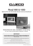
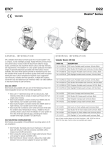
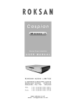
Riva2 & Studio
Electric Inset Range
Instructions for Use, Installation & Servicing
For use in GB & IE (Great Britain & Republic of Ireland).
IMPORTANT
THE OUTER CASING, FRONT AND GLASS PANEL BECOME EXTREMELY HOT DURING OPERATION AND WILL
RESULT IN SERIOUS INJURY AND BURNS IF TOUCHED. IT IS THEREFORE RECOMMENDED THAT A FIREGUARD
COMPLYING WITH BS 8423:2002 IS USED IN THE PRESENCE OF YOUNG CHILDREN, THE ELDERLY OR INFIRM.
For use with 230v 50Hz electricity supply only.
Please read these instructions carefully before installation and keep them in a safe place.
They will be needed when maintenance or servicing is required.
THIS APPLIANCE MUST BE EARTHED
PR1394 Issue 5 (June 2015 )
Contents
Covering the following models:
Riva2
Studio Inset
55
70
80
105
150
234-016
234-209
223-378
223-136
223-044
User Instructions........................................................3.
1. Important Information & Health and Safety............................. 3
2. Operating Instructions............................................................. 3
3. Maintenance............................................................................ 5
Installation Instructions.............................................6.
Technical Specifications.............................................................. 6
Appliance Dimensions................................................................. 7
Installation...................................................................8
1. General.................................................................................... 8
2. Fitting the Appliance................................................................ 8
3. Connecting to the Mains Supply............................................. 9
Servicing...................................................................10
1.
2.
3.
4.
5.
6.
7.
General Requirements.......................................................... 10
Fault Finding......................................................................... 10
How to Wire a Plug............................................................... 11
Servicing Requirements........................................................ 12
Cleaning................................................................................ 12
Removing the Glass.............................................................. 12
Resetting Remote Frequency............................................... 14
To receive your Extended Warranty your Gazco appliance must have
been purchased from our Expert Retailer Network and registered within
one month of purchase or installation. Please note that all warranties
are effective from the date of purchase. Any Gazco product purchased
outside of our Extended Retailer Network, or not registered within the
stated time will carry a standard 12 month warranty.
Full terms and conditions are detailed in the Warranty Statement on
the Gazco website www.gazco.com. In the event of any conflict of
information the wording on the website shall prevail.
Important Note: Should any problems be experienced with your
product, claims must first be submitted to the Expert Retailer where
the appliance was purchased from who will offer immediate assistance
or contact Gazco on your behalf.
Servicing - Replacing Parts.....................................15
1.
2.
3.
4.
5.
6.
7.
General.................................................................................. 15
Replacing the LED Assembly................................................ 15
Replacing the Silk Assembly................................................. 15
Replacing the Heater Unit..................................................... 16
Replacing the Effect Fan Assembly...................................... 16
Replacing the Powerplate Assembly..................................... 16
Paring the Remote Control to the Appliance......................... 17
Spare Parts List........................................................18
2
Registration No WEE/DH1656ZW
In accordance with European Directive 2002/96/
EC, waste electrical and electronic equipment
(WEEE) must not be disposed of with household
waste.
At the end of its useful life please take this
product to an appropriate recycling centre or
collection point. You can find your nearest
recycling centre by using the bank locator at
www.recycle-more.co.uk for UK customers,
www.weeeireland.ie for customers in the
Republic of Ireland, or by contacting your local
authority.
User Instructions
1. Important Information and
Health and Safety
1.1
Read all of the instructions carefully before using the
appliance.
1.2
Remove all packaging and dispose of at an appropriate
recycling facility.
1.3 Do not locate this appliance immediately below a fixed
socket outlet.
1.4
The glass panel on this appliance is considered by the
manufacturer to be a working surface which becomes warm
when the heater is switched on. You must use a suitable fire
guard to protect children, the elderly and the infirm.
1.17 This appliance is not intended to be used by persons
under the age of 12, persons with reduced physical,
sensory or mental capabilities or persons with lack of
experience and knowledge in the safe operation of the
appliance.
The appliance may be operated by persons above the
age of 12 provided they have been instructed in the safe
use of the appliance and that they understand the hazards
involved. Persons above the age of 12 may also operate the
appliance under the supervision of a responsible adult.
1.18 Parts of this appliance become hot whilst in operation and
under no circumstances should persons under the age of 12
be left alone with the product when it is in operation unless
a suitable fireguard is used to protect them against the
possibility of coming into direct contact with the appliance.
2. Operating Instructions
1.5 Do not use this appliance in the immediate surroundings of
a bath, shower, swimming pool or any other area where the
appliance could come into contact with water or humidity,
e.g. a bathroom.
1.6
WARNING! DO NOT COVER
Do not allow the appliance to be covered or let the air inlet/
outlet become obstructed as the appliance may overheat.
Please note the warning symbol on the appliance (see
above).
1.7
For indoor use only. This appliance is not suitable for use
outside the house.
1.8
Keep the power cord away from hot surfaces and hot
conditions. Do not route the power lead in front of the
appliance.
1.9 This appliance must be firmly fixed to a flat internal wall.
Ensure that furniture, curtains etc. are positioned no closer
than 1m to the front of the appliance.
1.10 When the fire has been installed the position of the plug
must be accessible.
WARNING! Do not operate the appliance if it is
damaged or has malfunctioned. If you suspect
the appliance is damaged or has malfunctioned
call a qualified service engineer to inspect the
appliance, and replace any part of the electrical
system if necessary, before reuse.
Do Not disconnect the power at the mains supply whilst
the appliance is running. Use the functions on the
remote to turn the fire off and ensure the isolation
switch has been moved to the off position before
disconnecting.
GENERAL
2.1
The appliance can be operated by the radio frequency
handset only.
PREPARATION BEFORE USE
Battery:
2.2
1.11 Where the electricity supply cable has to pass through a fire
place, stone surround etc. ensure suitable rubber bushes
are fitted at possible wear points.
Ensure that the handset battery is new and inserted correctly.
2.3
Dispose of old battery at an appropriate recycling facility.
1.12 If the electricity supply cable is damaged do not use the
appliance until it has been replaced. For safety reasons the
replacement has to be carried out by a Gazco service agent
or a similarly competent electrician.
When using the handset:
2.4
Ensure the handset is pointed at the appliance.
1.13 Do not use this appliance with any kind of timer,
programmer or thermal control or other device that will
switch the appliance on or off automatically.
1.14 Do not operate the appliance if it is damaged.
LOCATION OF POWER SWITCH
2.5
1
The isolation switch is located on the top right hand side of
the window of the appliance, see Diagram 1.
Isolation
Switch
1.15 Repairs of electrical appliances must only be performed by
an electrical engineer. Should the appliance fail to operate,
or in case of any damage, please contact the retailer from
whom the appliance was purchased.
1.16 Never leave the heater unattended while it is in use.
Always switch the product to the OFF position using the
isolation switch when leaving the appliance for a period of
time.
3
User Instructions
2.6
Move the switch to ON (—). Now the appliance can be
operated by the remote.
2.7
For periods of non use set the isolation switch to OFF (O).
Remote Operation
2.8
The following functions can be controlled using the remote
handset:
—On/Off - Flame effect
—Heat settings 1kW and 2kW
—Brightness of the fuel and flame effect
2.9
The flame effect can be turned off using the remote,
returning the appliance to Standby.
2
LED
A
B
Turning of the Heat:
2.14 To switch on the heating element the flame effect must be
running, then press button B:
The 1 kW heat setting is now functioning.
To increase the heat setting to 2 kW, press button D.
2.15 To decrease the heat setting from 2 kW back to 1 kW, again
press button D.
2.16 Pressing button D, allows the user to toggle between the
two heat settings.
If no heat is required, press button B. .
2.17 Press the On/Off (Button E) to turn off ALL settings and return to Standby.
2.18 The appliance should be turned off via the Isolation
switch when it is not in use.
The Variable Flame Effect
E
D
C
2.19 This appliance is equipped with a variable flame effect. This
enables you to control the brightness and appearance of the
flame effect display.
When the appliance is first switched on, (button A) the
brightness is automatically set to the factory default setting
of 70% brightness.
2.20 By pressing button C, the flame effect begins to cycle from
light to dark in appearance, this will continue on a loop until
the same button is pressed again.
Pressing this button (C) at any time within the loop, a user
setting for brightness can be established.
Standby On/Off
2.10 The appliance is in Standby mode when the power is
switched on via the isolation switch. You must have this
power supply ON (—) before using the remote control.
Turning On the Appliance
Please note the heat settings will only work with the flame
effect in operation.
The flame effect can be used without the heater in operation.
The remote control works by radio signal.
The handheld transmitter is configured in the factory with a
unique signal code.
IMPORTANT: If your handset loses signal or needs to be
replaced then, see Section 7 in Servicing Section for
details.
Flame Effects:
2.11 Pressing button A, switches on the flame effect. Please note
with every press of any button on the key pad, the red LED
will light to confirm each setting.
2.12 To switch the appliance to standby first turn the heater off
(Button D to return to 1kW, then Button B to switch the heater
off). You can then turn the appliance off using Button E.
2.13 To re-start the appliance, again use A, providing the isolation
switch has not been set to the off position.
Signal Code
Thermal Safety Cut Out
The appliance is fitted with a thermal safety cutout,
which operates if it overheats. If this happens:
2.21 Unplug the appliance and allow it to cool for 5 - 10 minutes.
2.22 Check the air inlets/outlets for any obstruction and clear if
necessary (see Maintenance, Section 3.5).
2.22 Plug in appliance and switch it on. The cutout will re-set and
the appliance should function correctly. If this is not the case:
2.24 Unplug once more and have the fire checked by a
competent electrician.
4
User Instructions
3. Maintenance
IT IS VERY IMPORTANT THAT THE AIR INLET GRILLES
ON THE UNDERSIDE OF THE APPLIANCE ARE
UNOBSTRUCTED AND ADEQUATE SPACE IS LEFT TO
ALLOW FREE CIRCULATION OF AIR AROUND THIS
AREA.
3.1
ALWAYS UNPLUG FROM MAINS SUPPLY BEFORE
CLEANING OR UNDERTAKING ANY MAINTENANCE
GENERAL CLEANING
3.2
Only clean the glass panel when it is cold. Do not use
abrasive cleaners.
3.3
Use a proprietary non abrasive glass cleaner and buff to a
clear finish with a lint free duster.
Caution: Do not use abrasive cleaners on the glass
panel. Do not spray liquids directly onto any surface of
the unit.
CLEANING AIR OUTLETS
3.4
Ensure the appliance is unplugged.
3.5
Clean the air outlet grilles regularly with a soft cloth or the
nozzle of a vacuum cleaner, see Diagram 3.
3
Air Outlets
Air Inlets
Dust build-up can inhibit efficient performance of the
fan and lead to the safety cut-out operating.
3.6
Keep the area around the appliance clean and free of fluff,
dust or pet hair.
3.7
In particular, build-up of dust etc. can occur around the heater area. Take particular care to keep this area free from
such particles on a regular basis to prevent build-up.
BATTERY REPLACEMENT
3.8
When the remote battery is low it must be changed
immediately. Install correct replacement and dispose of the
old battery carefully.
Note: If the appliance is to be left for a long period of
time ensure it is switched off and the power cord
unplugged.
5
Installation Instructions
Technical Specification
Covering the following models:
Riva2
Studio Inset
55
70
80
105
150
234-016
234-209
223-378
223-136
223-044
Model
Riva2 Electric
Weight - kg
(without surround or packaging)
Voltage
Battery Hand Transmitter
Decorative
Position
Electricity Consumption
Supply Cord
Heating
element
Studio Electric Insert
55
70
80
105
150
32
40
33
40
50
220/240V / 50Hz
220/240V / 50Hz
220/240V / 50Hz
220/240V / 50Hz
220/240V / 50Hz
12 V MN 21/23
12 V MN 21/23
12 V MN 21/23
12 V MN 21/23
12 V MN 21/23
13 Watt
15 Watt
25 Watt
35 Watt
50 Watt
1000 Watt
2000 Watt
2000 Watt
2000 Watt
2000 Watt
BS1363 UK13A
BS1363 UK13A
BS1363 UK13A
BS1363 UK13A
BS1363 UK13A
THIS APPLIANCE MUST BE EARTHED
This appliance has been certified for use in countries other than
those stated. To install this appliance in these countries, it is
essential to obtain the translated instructions and in some cases
the appliance will require modification. Contact Gazco for further
information.
Appliance Description
Riva2 Electric 2 55
Riva2 Electric 2 70
Studio Electric Inset 80
Studio Electric Inset 100
Studio Electric Inset 150
6
Fixing Kit containing:1
4
4
1
2
1
x
x
x
x
x
x
Instruction Manual
Screws
Rawl plugs
Handset
Retention screws
Battery
Installation Instructions
Technical Specification
RIVA 2 ELECTRIC
D
A
C
F
H
G
B
E
STUDIO ELECTRIC INSET
D
A
C
F
H
G
Model
A
B
C
Riva2 Electric 55
895
792
Riva2 Electric 70
1045
902
Studio Electric Inset 80
1145
622
Studio Electric Inset 105
1460
622
Studio Electric Inset 150
1877
622
B
E
D
E
F
G
H
167
852
755
550
550
152
167
1002
865
700
650
152
167
1102
585
800
380
152
167
1417
585
1050
380
152
167
1834
585
1500
380
152
7
Installation Instructions
1. General
IT IS VERY IMPORTANT THAT THE AIR INLET
GRILLES ON THE UNDERSIDE OF THE
APPLIANCE ARE UNOBSTRUCTED AND
ADEQUATE SPACE IS LEFT TO ALLOW FREE
CIRCULATION OF AIR AROUND THIS AREA.
1.1
TOOLS REQUIRED
A Screw Driver, Spirit Level and Drill will be needed.
1.2
UNPACKING THE FIREPLACE
WARNING! DO NOT use this appliance if any part has
been exposed to water.
Immediately call a qualified service technician to inspect and
to replace any part of the electrical system if necessary.
1.3
Carefully unpack the appliance.
Take care not to damage the surface of the appliance or the
installation area.
Keep plastic wrapping away from children.
Be responsible when handling the packing materials.
1.4
2.5
2.6
If the power cord is damaged, it must be repaired by the
manufacturer, its authorized service centre or professional
person.
The appliance should ideally be located close to a suitable
mains socket to enable connection. An extension could be
run from an existing socket outlet but this must be carried
out by a suitably qualified electrical engineer.
The electrical socket must be easily accessible to allow
disconnection when the appliance is fitted.
WARNING! KEEP ANY FURNISHINGS OR
COMBUSTIBLE MATERIALS AT LEAST 1M FROM THE
FRONT OF THE ELECTRIC FIREPLACE.
Installation into a
Mantel piece/Surround
1
Mantle piece/
Surround
Wall
Check all parts and accessories are removed before
disposing of any packaging.
If necessary keep the original packaging for future transport
and/or storage.
Appliance
Window
2. Fitting the Appliance
Take care when lifting the appliance, obtain assistance if
required and always follow safe manual handling
techniques.
There are two methods of installation:
1) Riva2 Electric 55 & 70 - installation into a mantel piece
or surround.
2) All Models - installation using 'Hidden Door' concept.
When in doubt consult your retailer or suitably qualified
person.
2.1
Locating The Appliance
Your new appliance may be installed virtually anywhere in
your home. However, when choosing a location ensure that
the general instructions are followed.
The positioning of the heater should ideally be fitted
into/onto a flat wall of block/brick construction or an
internal wooden frame plaster board wall. The fixings
provided are for use on brick walls ONLY. Please ensure
that suitable fixings are used when securing to any
hollow or cavity walls.
2.2
Always ensure the appliance is adequately supported and
sits on a firm structure when mounting above floor level.
2.3
Ensure that curtains and furniture are not positioned close to
the chosen position, as this would create a potential fire
hazard or block the heater outlet ducts.
2.4
For best results, install out of direct sunlight.
8
2.7
Do not insulate the appliance. For the heater to function it
requires air to circulate.
2.8
Ventilate the mantle piece/surround by allowing vents above
and below.
2.9
The positioning of the appliance should ideally be on a flat
surface or floor, or situated within a cavity secured using the
brackets provided.
2.10 Remove retaining screws and brackets (L/R), see Diagram 2.
2
Bracket
Installation Instructions
2.11 Re-attach the brackets (L/R) in reverse position and secure
using the fixings provided, see Diagram 3.
The fixings provided are for use on brick walls ONLY.
Please ensure that suitable fixings are used when
securing to any hollow or cavity walls.
The fixings supplied are for brick walls only.
2.17 Remove retaining screws and brackets (L/R), see Diagram 5.
5
Bracket
3
Bracket
2.12 Place any decorative infill panel into place ensuring the
cutout fits neatly around the 'Edge' frame leaving the edge
returns visible. Place the rebated mantel into place and
secure to the wall in accordance with the manufacturers
instructions.
2.18 Re-attach the brackets (L/R) in reverse position and secure
using the fixings provided, see Diagram 6.
6
Bracket
2.13 Ensure that curtains, furnishings and combustible materials
are not positioned closer than 1 metre to the appliance as
this could create a potential fire hazard.
Installation using the
'Hidden Door' method
4
Wall Cavity
2.19 Construct a studwork enclosure around the appliance to the
desired width and height. Finish the enclosure in the chosen
material ensuring the panels are pushed up to the 'Edge'
frame leaving the edge returns visible. Finish the wall as
desired.
Appliance
Window
10mm clearance to wall
2.20 Ensure that curtains, furnishings and combustible materials
are not positioned closer than 1 metre to the appliance as
this could create a potential fire hazard.
3. Connecting to the Mains Supply
Appliance
Base
2.14 Do not insulate the appliance. For the heater to function it
requires air to circulate.
2.15 Ventilate the cavity by allowing vents above and below to
allow air to circulate.
3.1
Check whether the mains circuit can accommodate the
additional load of 1000 or 2000 Watt.
3.2
Connect the appliance to an earthed socket.
3.3
Do not clamp the electrical lead.
2.16 The positioning of the appliance should ideally be on a flat
surface or floor, or situated within a cavity secured using the
brackets provided.
9
Servicing Instructions
1.1
1. General Requirements
THIS APPLIANCE MUST ONLY BE SERVICED BY A
SUITABLY QUALIFIED PERSON.
BEFORE UNDERTAKING ANY WORK ON THE
APPLIANCE: SWITCH OFF THE APPLIANCE AND
ISOLATE IT FROM THE MAINS BY UNPLUGGING THE
UNIT.
Wait for at least 10 minutes until the appliance has cooled down.
1.2 Remote Handset Battery Replacement
2. Fault Finding
Operate appliance before commissioning
2.1
Click on the Remote Handset flame button. If the appliance
does not function, then, follow points 1,2,3 and 4
respectively.
1. Check the power connection to the mains switch on the
wall is in the ON position.
2. Check the Isolation switch on the appliance (see sticker
on the appliance). The switch must be set to the "I" position
3. Check the battery in your handset. The red LED must be
showing brightly. Check if the battery is in the correct
position and refit if necessary.
4. If after checking 1, 2 & 3 nothing still has happened, then
disconnect the power from the mains (unplug from socket),
and wait for 60 seconds, then plug it back in and repeat
steps 1 to 4. If you do not have access to the mains switch,
because it is built-in, then disconnect from the fuse board.
5. On cold days or if the appliance is fitted in a conservatory,
the flame effect may move slowly (or appear to stick
slightly), when you first start it.
Turn on the heating by clicking on the bottom button for few
minutes. This will generate a stronger pull and will warm up
the glass.
The remote control handset, uses a battery for power
operation, this will need replacement over a period of time.
For replacement:
– Open the battery compartment cover on the rear of the
handset.
– Remove the old battery and replace with a new one
observing the correct polarity (+ & -) as marked upon the
battery and handset remote control.
– Replace the handset cover.
1.3
Maintenance of Motors
The motors used on the fan and flame effect are prelubricated for extended bearing life and require no further
lubrication. However, periodic cleaning/vacuuming of the
fan/heater unit is recommended.
1.4
Resetting the Thermal Cutout Switch
The appliance is fitted with an Electronic Safety Control
(E.S.). This is a safety device which switches off the heat
only if, the appliance overheats for any reason e.g. when
covered.
1.5
10
If the heater stops operating whilst the flame effect
continues normally, this indicates that the E.S. Control is in
operation.
The E.S. Control can only be re-set after the appliance has
cooled down.
To re-set the E.S:
Switch off the appliance (Isolation switch) and leave for
approximately 5-10 minutes.
Remove any obstruction to the fan heater outlet or other
internal parts.
Switch on appliance and the E.S. Control will re-set. Ensure
that the appliance is functioning correctly. If the E.S. Control
operates again, the appliance should be checked by a
competent Electrician.
If the power supply is interrupted (power failure) or the
appliance is turned off at the isolation switch whilst the
heater is on, it will be necessary to disconnect the appliance
from the mains supply and leave for 5 minutes in order to
discharge the electronics before attempting to turn the
appliance on.
6. The heating does not turn-on, when you click on heating
button but the flame effect is running.
a). Check the battery in your hand set. The red LED must
be showing brightly.
b). Try again clicking on heating button closer to the
appliance.
c). Turn off appliance, then turn it on again. Wait for 10
seconds, then click on the heating again.
d). If after checking a, b & c the heating still does not turn
on then follow point number 4.
Servicing Instructions
3. How to wire a plug
2
Typical European Plug
Type 15/16/17
To change the plug supplied with this fire, follow the instructions
below. The instructions assume that the wire has been cut.
WARNING – FAILURE TO CONNECT THE WIRES
CORRECTLY COULD PUT PEOPLE AT RISK FROM
ELECTRIC SHOCK OR FIRE. IF IN DOUBT
CONSULT A QUALIFIED ELECTRICIAN.
Neutral wire
Live wire
Earth wire
UK Plug
Outer Insulation
Suitable for use in Cyprus, Malta, Ireland & Great Britain
1
UK Plug Supplied
Type 33
Earth wire
3.1
Dispose of the old plug safely. Ensure the new plug is not
cracked or chipped.
3.2
Expose 4cm of the coloured wires and trim to the correct
lengths so that they comfortably reach the correct terminals.
3.3
Ensure that the Earth wire has more slack than any of the
other wires.
3.4
Remove some of the insulation to leave about 1cm of
exposed metal core on each wire. 3.5
Twist the strands of the wire together.
3.6
Loosen the screw heads above each terminal.
3.7
Push the metal wir e into the hole beneath each screw head
or, dependent on plug design, wind the metal wire around
the screw.
Fuse
Neutral wire
Live wire
Outer Insulation
Cable grip
Cable grip
Live Wire
Brown
Terminal L / RED
Neutral Wire
Blue
Terminal N / BLACK
3.8
Earth Wire
Green & Yellow
Stripes
Terminal E /
/ GREEN or
GREEN & YELLOW
Ensure that the insulation reaches right up to each terminal
as illustrated and there are no loose strands of wire.
3.9
Ensure the cable sits correctly under the cable grip and
tighten to secure.
THIS APPLIANCE MUST BE EARTHED
European Plug
3.10 Refer to Technical Specification for fuse rating and fit the
appropriate fuse into the plug.
3.11 Attach the plug cover.
Suitable for use in Austria, Belgium, Bulgaria, Czech Republic,
Denmark, Estonia, Finland, France, Greece, Hungary, Germany,
Italy, Latvia, Lithuania, Luxembourg, Netherlands, Poland,
Portugal, Romania, Slovakia, Slovenia, Spain & Sweden
11
Servicing Instructions
4. Servicing Requirements
4.1
CLEANING AIR OUTLETS
It is essential to regularly clean the air inlets to aid the
performance of the appliance.
Ensure the appliance is unplugged.
Clean the air outlet grilles regularly with a soft cloth or the
nozzle of a vacuum cleaner, see Diagram 3.
3
Air Outlets
4.5.6 Spray anti static on the back of the fire behind the screen
and on the silk.
Attach the silk and clip back into its original position.
4.5.7 Clean the effects screen and outer screen with screen
cleaner and cloth.
4.5.8 Clean the glass with glass cleaner and cloth.
4.5.9 Connect / restore mains electricity and ON/OFF switch back
to 1 position.
Run the fire while the screen and glass unattached following
steps 1,2 and 3, for 5 minutes.
4.5.10Turn off the fire from your RC.
4.5.11Attach screen and then attach the glass.
4.5.12Fit the HD trims.
4.5.13Run the fire while the screen and glass in place following
steps 1,2 and 3, for 3 minutes.
5. Cleaning
Air Inlets
Dust build-up can inhibit efficient performance of the
fan and lead to the safety cut-out operating.
4.2
To service the appliance please follow the steps as detailed:
5.1
Do not use water, detergents, abrasive cleaning powders or
polish of any kind on the body of the appliance. Lightly dust
using a dry duster or a medium soft brush.
To clean the glass use glass or window cleaner.
6. Removing the Glass
4.2.1 Click on the RC (flame) button. If appliance does not work,
then follow the Trouble shooting guide.
4.2.2 If it works then operate heat setting 1kW then, heat setting
2kW.
4.2.3 Click the dimmer function button, make sure the flame effect
goes from MAX brightness to a minimum and then start
cycling up and down.
4.3
4.4
4.5
If stages 2 & 3 are OK, then by using your handset turn off
the heat, turn off dimmer and then turn off the fire.
Turn off the switch on the fire. The Isolation switch on the
appliance must be set to the "0" position.
Turn off power connection mains switch on the wall to OFF
position. If you do not have an access to the MAIN’S ON/
OFF switch, because it is built-in, then disconnect from
MAIN’S fuse board.
Once these steps have been followed:
4.5.1 Change new Battery in the hand set.
4.5.2 Remove the glass trims attached with magnets.
Gently remove the glass from the fire, See Section 6.
4.5.3 Gently remove the effects screen and outer screen from the
fire.
4.5.4 Remove ONLY the Centre clip with the silk hanger (Note its
original position first)
4.5.5 Wipe and clean the back of the fire, with screen cleaner and
cloth and wait about 2 minutes to dry.
12
WARNING: REMOVING THE GLASS SHOULD
ONLY BE UNDERTAKEN WHEN ABSOLUTELY
NECESSARY.
IF REQUIRED PLEASE CONTACT YOUR
DEALER FOR FURTHER SUPPORT.
CAUTION: BROKEN GLASS CAN CAUSE
SERIOUS INJURY. TAKE EXTRA CARE WHEN
HANDLING THE APPLIANCE WINDOW
6.1
DO NOT OPERATE THE APPLIANCE WITHOUT THE
GLASS WINDOW INSTALLED.
6.2
Removing the Hidden Door brackets:
Lean side brackets inwards from magnets and lift away from
the appliance, see Diagram 4.
4
Servicing Instructions
6.3
Slide bottom bracket across and lift end upwards. Lift
bracket away from the appliance, see Diagram 5.
6.7
5
7
6.8
6.4
Grip the glass window with two hands and lift upwards,
lifting it out from its seated position, see Diagram 7.
Under the bottom bracket there are two window clamps
which hold the glass panel in place, see Diagram 6.
Once lifted, swing the glass backward and lower into the
bottom of the appliance, see Diagram 8.
8
6
A
A
6.9
9
Detail A
6.5
Remove the two screws from each clamp.
Lift off and place carefully to one side.
6.6
WARNING: Although the glass panel has been treated
with safety edges please take care when handling the
glass. Avoid contact with corners and if necessary wear
protective gloves.
Two people may be required to remove the glass.
The glass can now be lifted out of the appliance by gripping
the top edge with both hands and sliding out through the
window, see Diagram 9.
6.10 Clean glass panel and re-install following the instructions in
reverse.
Note: Hold the glass clamps in place against the glass panel
to ensure a tight fit when replacing.
13
Servicing Instructions
7. Resetting Remote Control Frequency
It may be necessary to reset the transmission frequency of
the existing Remote Handset or pair a replacement in the
event of loss or damage.
The reset switch is located on the PCB behind the
Electronics Cover Plate behind the appliances screens.
7.1
To access the Electronics Cover Plate it will be necessary to
remove the glass front, see Section 6.
7.2
It is then necessary to remove the inner screen assembly by
pulling the LH & RH upper snap fasteners towards you, see
Diagram 10.
7.6
In order to clear the current frequency setting press and
hold the button on the PCB for 10 seconds, see Diagram 12.
The relay will emit three beeps to signal that the operation
has been successful.
12
Frequency
Button
10
Snap
Fastener
7.7
In order to pair a remote handset to the appliance frequency
press the frequency button on the PCB and immediately
press any button on the handset at the same time.
Keep both buttons depressed for 5 seconds to complete the
pairing. The relay will emit a single beep to indicate the
pairing has been successful.
7.3
Pull the screen forward to clear the securing brackets and
lift screen to disengage from the lower retention channel.
Swing bottom of the screen assembly forward and remove
from the appliance.
7.4
Isolate the power supply and ensure there is no power to
the appliance.
7.5
The Electronics Cover Plate is located on the right hand
side of the Flame Effect. Loosen the screw to access the
PCB on the rear of the cover, See Diagram 11.
Take care when opening the Cover Plate not to damage
the wires attached.
11
Flame
Effect
Curtain
14
Screw
Cover
plate
Servicing Instructions - Replacing Parts
1. General
In order to carry out replacement of any of the
components, it will be necessary to remove the glass as
detailed in Servicing, Section 6.
1.1
It is then necessary to remove the inner screen assembly by
pulling the LH & RH upper snap fasteners towards you, see
Diagram 1.
1
Snap
Fastener
1.2
1.3
Pull the screen forward to clear the securing brackets and
lift screen to disengage from the lower retention channel.
Swing bottom of the screen assembly forward and remove
from the appliance.
Replace the screen by inserting into the top of the appliance
and then lowering into the retention channel before pushing
backwards at the top and pushing the snap fasteners back
into position.
2.6
Replace the glass screen and replace the bottom and side
decorative finishing brackets.
3. Replacing the Silk Assembly
3.1
The silk comes as a complete assembly with the retaining
clamp. To replace the assembly open electronics cover on
the inner RH side of the firebox, See Diagram 2.
3.2
Unplug the LED output lead from the PCB board and thread
the lead through the grommet back inside the firebox.
3.3
Remove the screws securing the silk assembly inside the
base of the firebox.
3.4
Unclip the silk from the top retaining bar by removing the
clips. It may be useful to mark the position of the silk on the
retaining bar to aid replacement.
3.5
Lay the new silk assembly flat and apply a fine film of antic
static spray to the material.
3.6
Position in the base of the appliance and fix into position
using the previously removed screws. Replace the silk on
top of the retaining bar in the position previously marked.
The indicator line on the top of the silk ribbons should be
aligned with the top edge of the retaining bar. Fold the silk
over and replace the clip, see Diagram 3.
Isolate the power supply and ensure there is no power to
the appliance.
2. Replacing the LED Assembly
2.1
2.5
3
The LED effect comes as a complete assembly. Open the
Electronics cover plate on the inner RH side of the firebox,
see Diagram 2.
2
Clips
Flame
Effect
Curtain
Cover
plate
2.2
Unplug the LED output lead from the PCB board and thread
the lead through the grommet back inside the firebox.
2.3
Unclip the LED boards from the silk bar by opening the
plastic retaining clips (which open from the bottom). Remove
the LED boards and replace with the new assembly.
2.4
Replace the clips and thread the lead back through the
grommet. Plug the clip back into the LED output port on the
PCB board.
Close the electronics cover plate and secure into position.
3.7
Replace the screen by inserting into the top of the appliance
and then lowering into the retention channel before pushing
backwards at the top and pushing the snap fasteners back
into position.
3.8
Replace the glass screen and replace the bottom and side
decorative finishing brackets.
15
Servicing Instructions - Replacing Parts
4. Replacing the Heater Unit
5. Replacing the Fan Assembly
4.1
Unclip the silk from the top retaining bar by removing the
clips. It may be useful to mark the position of the silk on the
retaining bar to aid replacement.
5.1
Remove the screws securing the silk assembly inside the
base of the firebox and remove the silk assembly from the
fan assembly.
4.2
Open the Electronics cover plate on the inner RH side of the
firebox, see Diagram 2.
5.2
Open the electronics cover plate on the inner RH side of the
firebox, see Diagram 2.
4.3
Disconnect the following leads:
5.3
Disconnect the fan leads from the PCB, See Diagram 4.
5.4
Locate the front securing nuts which are positioned beneath
the fan assembly to the left and right sides (Studio 150 also
has a centre securing nut), remove the nuts.
5.5
Remove the rear securing nuts and remove the complete
fan assembly.
5.6
Replace with the new assembly and replace all the nuts and
tighten.
5.7
Reconnect the supply leads to the Live and Neutral fan
supply terminals on the PCB.
5.8
Close the electronics cover plate and secure into position.
5.9
Resecure the silk assembly to the fan assembly using the
previously removed screws.
– Brown lead secured into Live Terminal Heater 1 on PCB
– Blue lead secured into Neutral Terminal Heater 1 on PCB
– White lead secured into Live Terminal Heater 2 on PCB
– Brown Heater Live lead from the Live Terminal 240v Inlet on PCB
– Brown Live Lead from the power unit socket situated at the bottom of the electric cover plate opening.
4.4
Undo the nuts securing the complete heater assembly in the
top of the firebox taking care not to damage the Earth lead
secured to the LH nut.
4.5
Remove the screws situated to both sides of the heater unit
and remove it completely ensuring the wires are gently
pulled through the grommet.
4.6
Locate the new heater unit and replace the screws to either
side of the heater. Replace the nuts securing the heater to
the top of the fire box ENSURING THE EARTH LEAD IS
SECURED BENEATH THE LH NUT.
4.7
Thread the leads back through the top grommet and replace
into the current locations as previously noted, see Diagram 4.
4
N
L
240v Inlet
Isolate the power supply and ensure there is no power to the
appliance.
N
Heater 2 Supply
6.1
The Electronics cover plate is located on the right hand side
of the Flame Effect. Remove the screw and lower the cover
plate to access the PCB, see Diagram 5.
Take care when opening the cover plate not to damage
the wires attached.
L
N
L
Heater 1 Supply
Fan Supply
Replace the silk on top of the retaining bar in the position
previously marked. The indicator line on the top of the silk
ribbons should be aligned with the top edge of the retaining
bar. Fold the silk over and replace the clip, see Diagram 3.
Close the electronics cover plate and secure into position.
4.10 Replace the screen by inserting into the top of the appliance
and then lowering into the retention channel before pushing
backwards at the top and pushing the snap fasteners back
into position.
4.11 Replace the glass screen and replace the bottom and side
decorative finishing brackets.
16
6. Replacing the Powerplate Assembly
LED Supply
N
4.9
5.11 Replace the glass screen and replace the bottom and side
decorative finishing brackets.
N
L
L
4.8
5.10 Replace the screen by inserting into the top of the appliance
and then lowering into the retention channel before pushing
backwards at the top and pushing the snap fasteners back
into position.
5
Flame
Effect
Curtain
Cover
plate
Servicing Instructions - Replacing Parts
6.2
Noting the orientation of the leads disconnect the following
from the PCB:
– 2x Fan Supply leads (Brown Live & Blue Neutral)
– 3x Heater Supply leads (Brown Live, Blue Neutral and additional White Live)
– 2x 240v Inlet leads (Brown Live & Blue Neutral)
6
2x 240v Inlet
LED Output
Lead
7. Pairing the Remote Control
to the Appliance
It will be necessary to reset the transmission frequency of
the new Remote Handset.
The reset switch is located on the PCB.
7.1
In order to clear the current frequency setting press and
hold the button on the PCB for 10 seconds, see Diagram 8.
The relay will emit three beeps to signal that the operation
has been successful.
8
LED adapter connection
3x Heater Supply Leads
2x Fan Supply Leads
6.3
Frequency
Button
Unplug the LED Output lead from the PCB and thread
through the hole in the cover plate, see Diagram 6.
6.4 Remove the Powerplate assembly.
6.5
Position the new Powerplate assembly.
6.6
Feed the LED supply lead through the hole in the
Powerplate and connect to the LED adapter on the new
Powerplate, see Diagram 7.
6.7
Reconnect all the leads, following the previous orientation,
see Diagram 7.
7
LED Adapter
7.2
In order to pair the new remote handset to the appliance
frequency press the frequency button on the PCB and
immediately press any button on the handset at the same
time.
Keep both buttons depressed for 5 seconds to complete the
pairing. The relay will emit a single beep to indicate the
pairing has been successful.
LED Output
Lead
2x 240v Inlet
3x Heater Supply Leads
2x Fan Supply Leads
6.8
Carefully lay the new Powerplate on its back, resting on the
fan assembly.
6.9
Ensure all leads are connected and reconnect the power
supply.
DUE TO THE CONSTRUCTION OF THE LED
CIRCUIT, IT MAY BE NECESSARY TO REVERSE THE
ORIENTATION OF THE BASE OF THE LED LEADS
ON THE PCB, IF THE LIGHTS FAIL TO OPERATE,
SEE DIAGRAM 8.
ISOLATE THE APPLIANCE FROM THE MAINS
BEFORE PERFORMING THIS OPERATION.
7.3
Once the handset and appliance have been successfully
paired:
– Isolate the appliance from the mains.
– Close the electronics cover plate and secure into position with the screw.
Take care when closing the cover plate not to trap or
damage the wires.
7.4
Replace the inner screen assembly and glass front.
7.5 Reconnect the power supply.
17
Servicing Instructions - Replacing Parts
8. Common Parts
Parts Description
Part No.
Remote Handset
ZA60020
Remote Battery
DE00132
Powerplate
ZA06017
Power Cable
DE00020
Feet inc Lock Nut
DE00133
Wall Mounting
DE00130
9. Model Specific Parts
Parts Description
Riva2 Electric 55
Riva2 Electric 70
Studio Electric
Inset 80
Studio Electric
Inset 105
Studio Electric
Inset 150
HD Side Trim Set (x2)
ZC05037
ZC06037
ZC07037
ZC07037
ZC07037
HD Bottom Trim
ZC05035
ZC06035
ZC07035
ZC08035
ZC09035
Outer Screen
ZC05098
ZC06098
ZC07098
ZC08098
ZC09098
Effect Screen
ZC05089
ZC06089
ZC07089
ZC08089
ZC09089
Glass Window
ZC05066
ZC06066
ZC07066
ZC08066
ZC09066
LED & Silk Clamp
ZC05016
ZC06016
ZC07016
ZC08016
ZC09016
Heater Unit
ZA05005
ZA06005
ZA07005
ZA08005
ZA09005
Fan Engine
ZA05006
ZA06006
ZA07006
ZA08006
ZA09006
18
Gazco Limited, Osprey Road, Sowton Industrial Estate, Exeter, Devon, England EX2 7JG
Technical Customer Services (01392) 261950 Fax: (01392) 261951
E-mail: [email protected]
A member of the Stovax Group
E&OE