1
United States Patent [191
[11]
[45]
-D0nnelly et al.
[54] METHOD AND APPARATUS FOR
SELECTIVELY PROCESSING PAGINATED
OUTPUT
[75]
Inventors: Kim F. Donnelly; Kurt A. Gluck, both
Patent Number:
5,023,811
Date of Patent:
Jun. 11, 1991
OTHER PUBLICATIONS
Word Writer ST, for ATARI SZOST and 1040ST Com
puters, TIMEWORKS User Manual, 1982.
R. B. K. Dewar, SPITBOL-68K Program Reference
of Piscataway, NJ.
Manual, Catspaw, Inc., Salida, Colorado, Mar. 1, 1987.
[73] Assignee: Bell Communications Research, Inc.,
Language, Prentice-Hall, Inc., Englewood Cliffs, New
R. E. Griswold et al., The SNOBOL4 Programming
Livingston, NJ.
Assistant Examiner-Mark K. Zimmerman
Attorney, Agent, or Firm-James W. Falk; Leonard
[21] Appl. No.: $35,991
[22]
Jun. 11, 1990
Filed:
Related US. Application Data
[63]
[51]
[52]
[5 3]
Jersey, 1971.
Primary Examiner—Gary V. Harkcom
Continuation of Ser. No. 257,218, Oct. 13, 1988, aban
cloned.
Int. Cl.5 ............................................ .. G06F 15/40
US. Cl. .................................................. .. 364/518
Field of Search ............. .. 364/518, 521, 522, 523;
358/311
Charles Suchyta
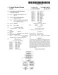
[57]
ABSTRACT
A data processing system for processing planar-oriented
computer output data to provide customized output for
each user. The system, called phaser, speci?es two-di
mensional portions of such planar-output for processing
to permit page-oriented editing of the planar output.
Portions of pages can be identi?ed by column and line
numbers, by box and block coordinates, and by match
ing plane-oriented patterns. Prior to processing, such
varied page speci?cations are converted to segment lists
of line segments to permit uniform processing. Phaser
[56]
References Cited
U.S. PATENT DOCUMENTS
4,357,624
4,719,585
4,803,643
4,833,625
11/1982
l/l988
2/1989
5/1989
Greenberg .................... .. 358/311 X
Cline
et
a1.
. .. ... .. ..
Hickey .............. ..
. . . . . . ..
statements are compiled and executed in working sets
which can be invoked in series or in parallel (on the
same data input) to permit union and intersection opera
tions.
364/518
364/523
6 Claims, 4 Drawing Sheets
Fisher et a1. ...................... .. 364/518
DATA
SOURCE
,11
COMPUTER
PROCESSING
,12
STANDARD
PLANAR
OUTPUT
,13
PHASER
PROCESSING
,14 '
CUSTOMIZED
PLANAR
OUTPUT
U.S. Patent
Sheet 1 of 4
June 11, 1991
FIG. 1
FIG, 3 -
DATA
SOURCE
START
,11
5,023,811
,21
PROCESSING
PLANAR
OUTPUT
PATTERNS
13
PHASERr
PROCESSING
r24
,23
,25
PHASER
COMPILE
PHASER
PROGRAM
PHASER com:
LISTING
f“
r27
r26
CUSTOM'ZED
STANDARD
EXECUTE
PLANAR
PLANES OF
PHASER
OUTPUT
DATA
CODE
,28
CUSTOMIZED
—
PLANES
0|: DATA
FIG. 2
@9
"’
THEN
@3?
@9
:
US. Patent
Sheet 2 of 4
June 11, 1991
5,023,811
FIG. 4A
replace
V
choose
remove
pages
columns
lines
strings
\---- pages
L
lines
T columns
strings
trom no() to no() -_--_J
from no() to no() --_'--J
from coord() to coord() _--J
boxes
lines
columns
E strings
DOXBS
3-K
from-patternQ to pattern()
rom every pat() to every pat()
\-_ blocks
segment(list) _______/
k_-- clouds
patternso _-_--_J
92
with()
To
FIG. 4B
U.S. Patent
June 11, ‘1991
Sheet 3 of 4
FIG. 4B
55
es
520:: —->- where
leftovers of
5
pages
r —
columns
\
lines
>
strings
\_
they
J
kt lines
from no() to no() -__-J
columns 3
strings 7-_- from coord() to coord() __J
boxes
lines
columns
4
from pattern() to pattern()
rom every ptn() to every ptn
strings
boxes
‘
\-_- blocks -_-_-___--_segment(list)-_____/
\-_ clouds --_--_-—- patterns()
.
i7.
contaln()
do not contain()
T»
_-__J
_
US. Patent
June 11, 1991
Sheet 4 of 4
TO
lloutfilell
5,023,811
1
5,023,811
2
on the page. That is, information is located either by the
content of the information, or by line and character
offset (column) location on the page. It should be noted
that the patterns and/or the physical locations need not
be contiguous. In order to permit common processing
of data identi?ed by these different locators, they are
' METHOD AND APPARATUS FOR SELECTIVELY
PROCESSING PAGINATED OUTPUT
This application is a continuation of application Ser.
No. 07/257,218, ?led Oct. 13, 1988, now abandoned.
both converted to a single descriptor form, for example,
A portion of the disclosure of this patent document
contains material which is subject to copyright protec
lists of line segments. Such a “segment list” can then be
used to control the processing of the data so identi?ed
tion. The copyright owner has no objection to the fac
to permit the selective display, replacement or omission
of the described data. In particular, data located by
pattern matching, for example, is converted to line seg
simile reproduction by anyone of the patent document
or the patent disclosure, as it appears in the Patent and
Trademark Office patent ?le or records, but otherwise
reserves all copyright rights whatsoever.
ment location and placed on the segment list in line
segment format.
TECHNICAL FIELD
The plane-oriented post-processing system of the
15
present invention therefore can process the data identi
This invention relates to digital data processing and,
?ed in the segment list by deriving other data from the
more particularly, to the selective post-processing of
data identi?ed on the segment list, or merely displaying
paginated output from digital data processing systems.
the identi?ed data in any desired format.
BACKGROUND OF THE INVENTION
A major advantage of the output-oriented post-proc
20
essing formatter of the present invention over the data
Many digital data processing application programs in
oriented, pre-processing formatters of the prior art is
use today produce output in the form of a sequence of
the ability to use the same formatter for many different
two-dimensional images or planes, exempli?ed by the
application programs, from word processing programs
printed page or the display on a cathode ray tube. Typi
cal examples of such application programs include
word processing programs, spread-sheet programs and
25
data base manager programs. The contents of these
to data base managing programs, and from spread-sheet
programs to information retrieval programs.
BRIEF DESCRIPTION OF THE DRAWINGS
images include all of the information obtained from the
operation of the application program, arranged or for
matted in a manner believed to be useful by the applica
A complete understanding of the present invention
may be gained by considering the following detailed
description in conjunction with the accompanying
drawing, in which:
tion programmer. Some limited ability to control or edit
these output images are sometimes included in the appli
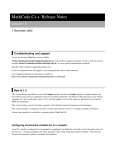
FIG. 1 shows a general block diagram of a page-ori
cation package. Unfortunately, however, such alternate
output formats must be provided either by laborious,
line-by-line manual editing of the original output, by
ented computer application program system showing
the post-processing phaser formatter in accordance
with the present invention;
hard coding of the new format by the application pro
grammer, or else a large and complex report generaton
must be included in the application program to allow
FIG. 2 shows a graphical example of the type of
post-processing that can be done on paginated output
the user to format his or her own output.
using the phaser system of the present invention;
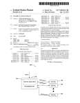
FIG. 3 shows a more detailed block diagram of the
The major disadvantage of the in?exible output for
phaser post-processing page-oriented processing system
mat is that it sometimes serves to conceal rather than
in accordance with the present invention;
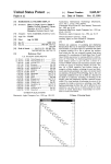
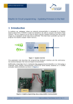
FIGS. 4A and 4B show graphical representations of
the syntax diagram for a compilation procedure that can
indirect manner in which it is displayed. The disadvan
tages of report generators associated with application 45 be utilized in the phaser system of the present invention;
and
programs are the time and difficulty in learning how to
FIG. 5 shows a flowchart of an illustrative phaser
use the report generator, only to ?nd that it is then
procedure showing the ordering of working set rou
necessary to learn a new report generator for a new and
tines.
different application program. The disadvantages of
To facilitate reader understanding, identical refer
manual editing are obvious.
.
reveal the desired data, due either to the sparsity of the
desired data among the total data output, or due to the
ence numerals are used to designate elements common
SUMMARY OF THE INVENTION
In accordance with the illustrative embodiment of the
present invention, these and other problems are solved
to the ?gures.
DETAILED DESCRIPTION
In
FIG.
1
there is shown a general block diagram of
by providing a general purpose application program 55
a computer system in which the present invention can
output post-processor system which permits the user to
selectively format, process and display portions of the
be used. The system of FIG. 1 includes a data source 10
data contained in a series of two-dimensional images for
which supplies the data to be processed by the com
puter system of FIG. 1. Typically, such data sources are
display or for printing. The post-processing system in
‘accordance with the present invention (hereinafter
called “phaser”) is independent of the application pro
60
located on magnetic disks, usually after being assembled
from large numbers of data generating stations such as
gram with which it is used and hence can be used with
point-of-sale terminals, banking terminals, business in
a wide variety of different application programs.
More speci?cally, the post-processing system of the
present invention looks at the two-dimensional plane
oriented outputs from any application program and
ventory control stations, and so forth. Data from source
selectively identi?es one or two-dimensional portions of
those outputs either by pattern content, or by location
10 is supplied to a standard computer processing system
11 which performs well-known types of computer pro
cessing steps on the data from source 10. A typical
result of such processing is the generation of a plurality
of “pages” of output. In this context, the term “pages”
3
5,023,811
includes successive cathode ray tube screen images, or
'any other two-dimensional, planar output, as well as
printed pages. Such output can be categorized as stan
dard planar output 12 from computer processing system
4
community, since the methodology and the conventions
for the new report generator are normally different
from other prior report generators. It is another signi?
cant advantage of the present invention that the phaser
processing system 13 can be applied to the paginated,
11. The major problem with such output, as anyone
who has had to deal with it fully understands, is that the
planar output from any computer processing system 11,
speci?c data the user requires is most often buried some
where in a very large volume of data, spread over a
images on a terminal screen, that is, as long as the output
provided only that the output is divided into pages or
large number of possibly non-successive pages of data,
_is a succession of two-dimensional data arrays which
the majority of which is not of interest to that user. It is
to the solution of this problem that the present invention
is directed.
In accordance with the present invention, the stan
can be divided into rows and columns, into lines and
characters, or into any other two-dimensional coordi
nate identi?ers.
dard planar output 12 from the computer processing
system 11 is applied to a special post-processing system
13, hereinafter called the “phaser” processing system.
The function of the phaser processing system 13 is to
analyze the planar output from block 12, to select the
available in the prior art, in order to use these report
generators, the data base itself must be reformatted to
the speci?cations of the report generator and the data
base manager supplied with the report generator used to
user’s needs.
and hence it can be used to convert a stream of data,
Although general purpose report generators are
access information from the data base. The difficulty
with this arrangement is the obverse of the dif?culties
portions of that output desired by the present user, to
further process such selected portions, if required, and 20 pointed out above. That is, the data base universe has to
be tailored to the particular report generator whereas,
to display the results of such further processing, along
above, the report generator universe had to be tailored
with whatever portions of the original output are de
to the particular data base. Neither arrangement deals
sired. The result of the operation of phaser processing
ef?ciently with the actual data base arrangements pres
system 13 is customized planar output 14 which in
cludes all of the data wanted by the user, and only the 25 ent in the real world. The major advantage of the pres
ent invention is the provision of tailored output from
data wanted by the user, reformatted and further pro
any data base by tailoring the user-readable output of
cessed in exactly the manner wanted by that user. Other
the data base rather than the data base itself. Indeed, it
users of the same standard planar output 12 can use the
is possible for the system of the present invention to
same phaser processing system 13 to provide another,
convert data which is not paginated into paginated data,
different customized output 14 suitable for the other
originally intended for electronic consumption, into a
series of pages useful for human readers.
It is to be noted that the purpose of customizing the
users, or to customize the output for a particular user, 35 output of a particular computer processing system 11
may be to transfer the customized data on to another
given adequate time and resources. In either case, how
computer processing system rather that to present the
ever, the customization was “hard coded” into the ap
data to the user. The phaser system of the present inven
plication program, not thereafter readily susceptible to
tion is perfectly suitable for this arrangement and, in
changes by the user'. Different users, of course, required
doing so, can reduce the delay in performing such fur
different customizations, all at signi?cant costs in time
ther processing to virtually zero. It should also be noted
and other resources. It is a signi?cant advantage of the
that one very important use of decimated computer
phaser processing system 13 of the present invention
processing output is in regression testing. Regression
that the format and content of the customized planar
testing generally involves the comparison of the outputs
output 14 is entirely under the control of the user.
It was also possible in the prior art for the supplier of 45 from new and old versions of the same program. If they
are identical, the new version is considered to be cor
the particular computer processing system 11 to include
rect. In regression testing, it is undesirable to compare
in the application software a more or less general pur
all of the output since the time required would be pro
pose report generator. Such report generators had the
hibitive and some portions of the output tend to be date
capability of allowing the user to select the data and the
format for the planar output 12, thus supplying one of 50 or time dependent and hence not comparable. Regres
sion testing is therefore the art of selecting test cases
the needs met by the present invention. Unfortunately,
which are typical, repeatable, and cover all of the major
however, such report generators are at least as complex
capabilities of the system. The decimation of the output
to implement as the application itself, and hence expen
data from the new and old versions of the same program
sive to provide. Furthermore, the degree of variation
permitted in formatting or data content was limited, 55 for regression testing comparisons is a major use of the
phaser processing system of the present invention.
dependent in part on the software supplier’s view of the
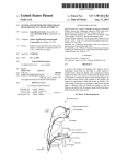
In FIG. 2 there is shown a typical example of the type
needs of the ultimate user. For example, many report
of post-processing of paginated output permitted by the
generator programs simply permitted the user to dis
phaser processing system 13 of the present invention. In
play or not display the contents of speci?c ?elds in the
FIG. 2, there are shown three different views 15, 16 and
data records‘, with no more sophisticated selection crite
17 of the same paginated portion of the output from a
ria and no further processing possible. More impor
computer processing system such as system 11 of FIG.
tantly, such report generators were speci?c to the appli
1. Page 15 shows a window 18 containing the data
cations software in which they resided. Hence, when a
In the prior art, it was always possible for the supplier
of the particular computer processing system 11 to
customize the output for the imagined needs of future
characters “origin” in the lower, central portion of page
new application processing system 11 is used, an en
tirely new report generator must be provided or de 65 15. As suggested by the text between the pages 15-7, the
appearance of the characters “o-r-i-g-i-n” in window 15
vised. In addition to the cost and delay time in provid
causes the contents “France” of window 19 in the upper
ing such new report generators, it is typical for the new
right hand corner of page 16 to be changed to “Italy” in
report software to require retraining of the entire user
5,023,811
5
and conditional pattern changing is only typical of the
phaser processing system 13 of the present invention.
Virtually any other type of two-dimensional processing
is possible.
The general types of analysis actions available in the
phaser system are replace, choose, remove and replace
3. choose <object1> [where <object2> <contain
phrase> <pattern>]. The current text set will be
modi?ed to include only the <objectl> portion of
the input text if the <object2> portion of the input
text meets the speci?cations of the where clause.
remove <object1> [where <object2> <contain
phrase> <pattern>]. The current text set will be
everything but. Combinations of these four basic ac
tions provide virtually universal ?exibility in decom
modi?ed so that it will not include the <object1>
posing paginated output. Similarly, the general catego
portion of the input text if the <object2> portion of
ries of objects upon which these actions can be taken are
the input text meets the speci?cations of the where
virtually universal. Thus, the replace, choose, remove
clause.
and replace everything but actions can be applied to
pages, lines, columns, strings, boxes (like windows 19 in
5. replace <object1> with <string> [where <ob
ject2> <contain phrase> <pattern>]. The current
FIG. 2), blocks (lists of strings, not necessarily contigu
text set will have the <object1> portion of the input
text replaced with repetitions of the with string only
ous), and “clouds” (entire pages treated as one continu
ous string for SPITBOL® pattern searches). SPIT
BOL patterns are described, for example, in SPITBOL
68K Program Reference Manual, by R. B. K. Dewar,
if, and only if, the <object2> portion of the input
Catspaw, Inc., Salida, Colo., 1987. SPITBOL is a dia 20
lect of the SNOBOL language, described in The SNO
BOL4 Programming Language, R. E. Griswold et al.,
Prentice—Hall, Englewood Cliffs, N.J., 2nd Ed., 1971.
The pages of information thus decomposed by the re
place, choose, remove and replace everything but ac
tions can be recomposed however the user wishes by
the merge action which recombines the decomposed
elements into new pages with new formats.
In operation, the user of the phaser system of the
present invention describes the post-processing desired
6
2. end <working set name>. This statement is used to
mark the end a working set.
_ window 19 of page 17. This type of pattern recognition
25
text meets the speci?cations of the where clause.
. replace everything but <object1> with <string>
[where <object2> <contain phrase> <pattern>].
The current text set will have everything in the input
text set but the <object1> portion of the input text
replaced with the with string if, and only if, the <ob
ject2> portion of the input text meets the speci?ca
tions of the where clause.
7. merge <mergetype> <mergeobject1> <mergeob
ject2>. Merge successive pairs of plane objects
(pages from ?les or from working sets) side-by-side,
one-after-another or line-by-line (mergetypes). Plane
objects may be the current working set plane con
by a sequence of statements involving the actions and
tents, a plane read from a ?le, or a remembered plane.
objects described above. These statements make up a
8. pad on the <direction> with <number>
phaser program and are used by the phaser system as
<string>. Add <number> copies of <string> on
described in connection with FIG. 3. Turning then to
the <direction> side of the current working set 7
FIG. 3, there is shown a ?owchart of the phaser pro 35
plane. The direction is right or left.
cessing system 13 of FIG. 1. The process of FIG. 3
9. remember as <name>. Save a copy of the contents
starts in start box 20. In box 21, most of the variables
of the current working set plane for later retrieval
used in the phaser system of FIG. 3 are initialized. Simi
under the key <name>.
larly, in box 22, most of the patterns used in the phaser
l0. translate from <string1> to <string2>. Replace
system are initialized. The phaser program 24 consists
single character in <string1> with single characters
of a number of statements inv'olving actions and objects
in <string2>. This could be done with replace, but
as described above. In box 23, the phaser program is
not as ef?ciently.
11. write <string> to <?lename>. Store a literal
string in a ?le.
box 23 is executed in box 26 to translate the standard 45
12. print to <?lename>. Print the contents of the cur
planes of data 27 into the customized planes of data 28,
rent working set to <?lename>.
all in accordance with the user’s wishes as expressed in
The
“objects” of the above action statements can be
phaser program 24.
any one or two-dimensional regions on an input plane,
The phaser program 24 of FIG. 3 is typically divided
not necessarily contiguous. Such regions can be de?ned
up into a number of working sets, each working set
in terms of page numbers for groups of pages, line num
de?ning the processing steps to be carried out on one set
bers, ranges or patterns for groups of lines, column
of input data to produce one particular data output. A
numbers, ranges or patterns for groups of columns,
phaser program can include any number of such work
coordinates or patterns for strings, and coordinates or
ing sets, each working set working on a different data
input set, or providing different processing steps for the 55 patterns for a rectangular box. Other de?nitions of re
gions include “clouds” de?ned by patterns and
same input data. The basic phaser statement types are
“blocks” de?ned by lists of line segments. These rela
de?ned below, where <argument> is a variable name,
compiled and a phaser listing 25 produced for assistance
in trouble shooting. The phaser program compiled in
where capital letters identify the prede?ned actions,
where “objects” are as de?ned above, and where square
brackets around an argument indicate that the argument
is optional:
1. de?ne <working set name> using <using group>.
tionships between the actions and the regions will be
discussed in connection with a discussion of the syntax
diagrams of FIGS. 4A and 4B.
Before turning to FIG. 4A, it should be noted that a
phaser statement is a section of source code beginning‘
with one of the action words identi?ed above (de?ne,
This statement is used to mark the beginning of a
end, replace, choose, remove, etc.) and ending withra
working set. The working set name is the unique
name of this working set. The using group in the 65 semicolon. A phaser working set is a plurality of phaser
statements introduced by a de?ne statement and termi
using clause is a list of the inputs to this working set,
nated by an end statement. A phaser program is one or
including ?lenames (in parentheses) or set names of
more working sets. Note that the input to a working set
other working sets.
'
7
5,023,811
8
ing is necessary. Some regions translate directly into
_ can be the output of one or more other working sets as
well as the contents of one or more data ?les. By pro
segment list notation (lines and columns), but some can
cessing working sets in a user-de?ned order, the phaser
system is able to perform logical unions and intersec
tions of the working set parameters. That is, sequential
working sets are ANDed and parallel working sets are
be translated to segment list notation only after the data
ORed.
include portions of overlapping segments. vWhile the
system would operate properly with such overlapping
is identi?ed, e.g., by pattern matching.
Since segment list items can arise from a variety of
phaser statements, it is possible for various items to
With the above as a background, the syntax diagram
of FIGS. 4A and 43 can now be considered. The syntax
items, the processing would be less than optimum since
diagrams of FIGS. 4A-4B are so-callecl “railroad” dia l0 certain segments would be treated more than once. In
grams. In these diagrams, movement takes place
order to eliminate such multiple processing, each seg
through the diagram from left to right and various
branches can be entered as if railroad switches were
ment list, just prior to processing, is sorted, duplicate
objects affected by these actions and their respective
3 can also be represented by the following pseudo-code
position speci?cations are found at reference numeral
41. Note that all possible combinations of actions, ob
jects and position speci?cations are accounted for in the
in Table I:
segments eliminated and overlapping segments com
operated to permit access to that branch. The direction
bined
into a single segment. A simple comparison of line
of the branch curves suggests the unidirectional nature 15
numbers and column numbers readily permits such
of the branching.
segment list optimization.
'
In FIG. 4A, the action words of the working set
The phaser system represented in block form in FIG.
statements are found at reference numeral 40 while the
TABLE I
main ( )
syntax diagram. At reference numeral 42, the replace
de?ne variables
de?ne patterns
ment value is available for the replace statements. In
FIG. 4B, the conditional where clauses are taken care of 25
parsegen ( )
while input
getstat ( )
at reference numeral 43 with the objects and position
specification named in the WHERE clause appearing at
reference numeral 44. Finally, at reference numeral 45,
the text comparison patterns are accounted for. Using
the syntax diagram of FIGS. 4A and 4B, the generation
of a compiler for phaser statements is straightforward
read statement
if defset
then
start workingset code
end then
else if endset
then
and obvious to persons skilled in the compiler art.
It will be noted that the phaser system allows two-di
terminate workingset code
mensional objects in the planar output of a computer
processing system to be described in a wide variety of 35
ways: page numbers, column and line numbers, patterns
in strings, boxes, blocks and clouds, and so forth. In
end then
else if intersperse merge
then
buildintersperse
end then
else if action statement
then
buildcode
end then
else if merge statement
then
order to process the contents of such objects, it is essen
tial to provide a common representation of the informa
tion location in the planar output, regardless of how
such information was described by the user. The com
mon representation used in the phaser system is called
the “segment list.” A segment list is a list composed of
all of the line segments making up the data identi?cation
of an object and its descriptors. Such segment lists are
45
composed of items which take the form:
buildmerge
end then
end else
end getstat
end parsegen
process ( )
(a. b-c)
if no endset
then
where a is the line number in which the line segment is
located, b is the starting column number of the line
segment and c is the ending column number of the line
segment. The asterisk (“""’) is used as a wild card value
add endset
end then
end if
?leroutine ( )
while no NULL
in segment list items to simplify representations. Thus,
“(*, b-c)” represents the segments between columns b
readpage ( )
and c for all lines, “(a, b-“)” represents the segment on 55
line a from column b to the end of the line, and “(‘,
l—")” represents an entire page. Data in the planar
output of a computer processing system is located in
terms of all of the locators described above, including
pattern matching. Once located, however, all informa
60
rout (workingsets)
end while
end ?leroutine
end process
end main
The de?ne routines create all of the ?xed variables
and ?xed patterns to be used in the balance of the pro
tion speci?cations internal to the phaser system are kept
in the form of segment lists and passed between pro
gram. The parsegen routine is the compiler, using the
cesses in this form. It is therefore unnecessary to pro
syntax of FIGS. 4A and 4B, to create executable code
from the phaser statements. For example, getstat gets
vide special processing routines for all of the different
forms of data identi?ers available in the system (FIGS. 65 the next phaser statement (terminated by a semicolon).
The defset routine sets up the data structures speci?ed
4A-4B). All internal processing is done on segment lists,
as input and the working set-data structure control
and all data representations are converted to and from
the segment list representation whenever any process
structures necessary to identify and eventually execute
5,023,811
9
each working set against the appropriate data struc
tures. The buildcode, buildmerge and buildintersperse
routines create the actual executable code for the action
statements, merge statements and intersperse state
ments, respectively. The endset routine terminates the
working set and triggers the actual compilation of the
working set code.
In TABLE I, the process routine actually executes
the compiled phaser executable code. First, the endset
10
The result of compiling and executing the phaser
program of TABLE II is shown graphically in FIG. 5.
Each box in FIG. 5 represents a working set. Thus the
contents of “?lel” are operated on (by way of line 50)
by working set 51, identi?ed as working set “a.” The
output of working set 51 is routed to both working set
52 (“b”) and working set 53 (“c”). The outputs of work
ing sets 52 and 53 are both routed to the input to work
routine is called in case the ?nal END statement is
ing set 54 (“:1”). Thus, the output of working set 54 on
leads 55 is the ORed combination of working sets 52 and
missing. The ?leroutine routine loops through the input
53, subject to (ANDed with) the post-ORing operations
?les identi?ed in the de?ne statements (up to an end-of
of working set d. It is clear that any other Boolean
combination of operations can be performed on the
?le, EOF), passing the input planes of data, one by one,
input data simply by appropriately specifying the work
working set which speci?es this ?le in its using clause, 15 ing set inputs. In this sense, phaser applies a very large
and executes the compiled working set against that grain data flow (one plane at a time) to the editing of
plane. The rout routine also ?nds the working sets
collections of plane-oriented output. Moreover, the
which must follow other working sets (in accordance
phaser commands exploit the two-dimensional aspects
on to the rout routine. The rout routine ?nds ‘each
with the using clause of the de?ne statements) and in
sures proper ordering of the execution of the working
sets. Execution of the working set code continues until
the input has been exhausted and all planes have been
processed. SPITBOL code descriptions of each of these
routines can be found in the Appendix to this applica
tion.
An illustrative example of a phaser user-program will
be given to aid in the understanding of the present in
of the planar output to transform two-dimensional ar
rays or patterns of alphanumeric data by ?ltering each
page-sized plane through a virtually arbitrarily pre
scribed network of plane-oriented ?lters.
It should be clear to those skilled in the art that fur
ther embodiments of the present invention may be made
25
by those skilled in the art without departing from the
teachings of the present invention.
vention. It is to be understood that this example is illus
trative only, and should not be treated as limiting in any
sense. Indeed, the illustrative example was chosen to be 30
relatively simple to aid in the understanding of the in
vention. The following phaser program is illustrative:
TABLE II
de?ne at using (?lel);
remove pages where they contain ‘xyz';
de?ne b using a;
remove pages where they contain ‘abc’;
end b;
35
de?ne c using a;
remove pages where they contain ‘111’;
end c;
40
de?ne d using b, c;
replace strings with ‘xyz’ where they contain ‘kag‘;
print to (out?le);
end d;
45
APPENDIX
-LIST_
a
‘
COPYRIGHT (C) 1988 BELL COMMUNICATIONS RESEARCH
'
5
ALL RIGHTS RESERVED
'
'
a
_ -TITLE
PHASER
.
-
a
a
10
—STITL
'
ALISEGSFROMPT
DEFINE(’ALISEGSFROMP'KSHAPEPAGEYISHARPI,P2,CNT,C3,’
+
+
+
’C1,CN'IZCLTEMPLHEAD,CURRENI‘,GREATER,TONEWLIST,LESS,’
’OLDHEAD2’)
:(ENDAKISEGSFROMP'I)
27
+
CNT')
5,023,811
28
~ _
+
:(END_ENLARGEPAGE)
ENLARGEPAGE
+
PRO'IO: PROTOTYPE(PAGE)
' PRO'I0= BREAKX(":") ." LOW ":" NUMBER. OLDHIGHRPOS(0)
HIGH: CONVERT(HIGH' 1.5, ’INTEGER’)
L'I‘(HIGH,PAGESIZE + 10)
'
:S(GO_§NLARGEPAGE)
OUILISTING = OUI‘LISI‘ING_MSG
_ +
_
.
I
"PAGE SIZE EXAUSTED- ENLARGING PAGFS FROM: "
+
'(OLDHIGH - 10) " T02’ !' (HIGH - 10) _
_N.UILARRAY= ARRAY(LOW '2" HIGH)
NULLARRAY< 1> = BOL
_
'
l ‘
.
.
-
‘
EOFARRAY= COPY(NULLARRAY)
EOFARRAY< 0> = EOF
PAGESIZE: HIGH-10
GO_ENLARGEPAGE
+
ENLARGEPAGE: COPY(NULLARRAY)
LOOP_ENLARGEPAGE
+
ENLARGEPAGE< CNT> = PAGE< CNT>
CNT= LT(CNT,HIGH) DIFFER(ENLARGEPAGE< CNT> ,BOL)
+
CNT+ 1
:S(LOOP_ENLARGEPAGE)F(RETURN)
END_ENLARGEPAGE .
-STI'IL
_
FILEROUIINE - FILEROUIINES
DEFINECFHEROUI'INEOTUPIN’) :(END_FILEROU1'INE)
FILEROUIINE
‘
.
NEWPAGEjlLEROUIINE
8
"
GET CURRENT FILENAME
’
.
TUPIN =
5
_
v
‘s .
I,1>
GET LIST OF DEPENDEN'IS OR CURRENT FILE
LISTZOFDEP = 'TEMPASSO< TUPIN>
O.
IF I AM READING NON-ROUNDROBIN, CALL READAPAGE
IF I AM READING ROUNDROBIN, CALL READORNULL
IDENI‘(DEFAULTREAD,’ROUNDROB1N) :S(ROUNDROB1__FEEROUIINE)
O
PAGE= READAPAGE(’READ1IH11’,TUPIN)
PAGE = -READAPAGE(TUP1N) ' -
+
_
~ r
'
‘I
:F(RETURN)S(ROUNDR2_FILEROUI1NE)
ROUNDROB1__FILEROUHNE "
PAGE: READORNULLU'UPIN)
* BUMP PAGECNT
ROUNDR2 FILEROUI'INE
+
PAGECNT= PAGECNT+ 1
I‘.
FOR EACH DEIZENDENT WORKING SET SEND PAGE THROUGH
MOREDEP_FILEROUTINE v
+
LIST2OFDEP ’;’ WORD . DEPENDENT = :F(ISNEWPAGE_FILEROUIINE)
x’ IDENT(LOOPCHECK1NG,’OFF)
- :S(CALIST__FILEROUTINE)
IDEN'IIDEPENDENETUPIN)
:F(CALIST_FILEROUIINE)