1
705JICSUM/D
January 1998
M68HC705JICS
IN-CIRCUIT SIMULATOR
USER'S MANUAL
© MOTOROLA, Inc., 1998; All Rights Reserved
Important Notice to Users
While every effort has been made to ensure the accuracy of all information in this document,
Motorola assumes no liability to any party for any loss or damage caused by errors or omissions
or by statements of any kind in this document, its updates, supplements, or special editions,
whether such errors are omissions or statements resulting from negligence, accident, or any other
cause. Motorola further assumes no liability arising out of the application or use of any
information, product, or system described herein, nor any liability for incidental or consequential
damages arising from the use of this document. Motorola disclaims all warranties regarding the
information contained herein, whether expressed, implied, or statutory, including implied
warranties of merchantability or fitness for a particular purpose. Motorola makes no
representation that the interconnection of products in the manner described herein will not
infringe on existing or future patent rights, nor do the descriptions contained herein imply the
granting or license to make, use or sell equipment constructed in accordance with this
description.
Trademarks
This document includes these trademarks:
Motorola and the Motorola logo are registered trademarks of Motorola Inc.
IBM is a registered trademark of IBM Corporation.
Windows is a registered trademark of Microsoft Corporation.
CASM05W, ICS05JW, and WinIDE software are P & E Microcomputer Systems, Inc, 1996;
all rights reserved.
Motorola Inc. is an Equal Opportunity /Affirmative Action Employer.
CONTENTS
CONTENTS
CHAPTER 1
1.1
1.2
1.3
1.4
1.5
1.6
1.7
Overview............................................................................................................................. 1-1
Toolkit Components ........................................................................................................... 1-2
Hardware and Software Requirements ............................................................................... 1-3
Toolkit Features .................................................................................................................. 1-3
Specifications...................................................................................................................... 1-4
About This User’s Manual.................................................................................................. 1-4
Quick Start Instructions ...................................................................................................... 1-5
CHAPTER 2
2.1
2.2
INTRODUCTION
POD INSTALLATION
Overview............................................................................................................................. 2-1
Installing the M68HC705JICS Pod .................................................................................... 2-1
CHAPTER 3
INSTALLING AND INITIALIZING THE ICS05JW SOFTWARE
3.1
3.2
Overview............................................................................................................................. 3-1
The ICS05JW Software Components................................................................................. 3-1
3.2.1
WinIDE................................................................................................................... 3-1
3.2.2
CASM05W ............................................................................................................. 3-2
3.2.3
ICS05JW................................................................................................................. 3-2
3.3 Installing the ICS05JW Software ....................................................................................... 3-3
3.3.1
To Install the ICS05JW Software ........................................................................... 3-3
3.3.2
To Start the ICS05JW Software ............................................................................. 3-4
3.3.3
Pod Communication ............................................................................................... 3-4
705JICSUM/D
iii
CONTENTS
CHAPTER 4
THE WINIDE USER INTERFACE
4.1 Overview............................................................................................................................. 4-1
4.2 The Windows Integrated Development Environment ........................................................ 4-1
4.3 WinIDE Windows .............................................................................................................. 4-2
4.3.1
Main Window Functions ........................................................................................ 4-2
4.3.2
Main Window Components.................................................................................... 4-2
4.4 Getting Started .................................................................................................................... 4-3
4.4.1
Prerequisites for Starting The WinIDE Editor........................................................ 4-3
4.4.2
To Start The WinIDE Editor................................................................................... 4-3
4.4.3
To Open Source Files ............................................................................................. 4-4
4.4.4
To Navigate In The WinIDE Editor ....................................................................... 4-4
4.4.5
Using Markers ........................................................................................................ 4-5
4.5 Command Line Parameters................................................................................................. 4-6
4.6 WinIDE Toolbar ................................................................................................................. 4-7
4.7 WinIDE Menus................................................................................................................... 4-8
4.8 WinIDE File Options........................................................................................................ 4-10
4.8.1
New File................................................................................................................ 4-10
4.8.2
Open File . . . ....................................................................................................... 4-10
4.8.3
Save File ............................................................................................................... 4-11
4.8.4
Save File As . . . ................................................................................................... 4-11
4.8.5
Close File .............................................................................................................. 4-12
4.8.6
Print . . . ............................................................................................................... 4-12
4.8.7
Print Setup . . . ..................................................................................................... 4-12
4.8.8
Exit........................................................................................................................ 4-13
4.9 WinIDE Edit Options ....................................................................................................... 4-13
4.9.1
Undo ..................................................................................................................... 4-13
4.9.2
Redo...................................................................................................................... 4-14
4.9.3
Cut ........................................................................................................................ 4-14
4.9.4
Copy...................................................................................................................... 4-15
4.9.5
Paste...................................................................................................................... 4-15
4.9.6
Delete.................................................................................................................... 4-15
4.9.7
Select All .............................................................................................................. 4-15
4.10 WinIDE Environment Options ......................................................................................... 4-16
4.10.1 Open Project ......................................................................................................... 4-17
4.10.2 Save Project .......................................................................................................... 4-17
4.10.3 Save Project As . . . .............................................................................................. 4-17
iv
705JICSUM/D
CONTENTS
CHAPTER 4
THE WINIDE USER INTERFACE (continued)
4.10.4 Close/New Project ................................................................................................ 4-18
4.10.5 Setup Environment . . . ........................................................................................ 4-18
4.10.5.1 The General Environment Tab...................................................................... 4-18
4.10.5.2 The General Editor Tab ................................................................................ 4-20
4.10.5.3 The Assembler/Compiler Tab........................................................................ 4-22
4.10.5.4 The Executable 1 (Debugger) And Executable 2 (Programmer) Tabs......... 4-26
4.10.6 Setup Fonts ........................................................................................................... 4-28
4.11 WinIDE Search Options .................................................................................................. 4-29
4.11.1 Find . . . .................................................................................................................... 4-30
4.11.2 Replace . . . .............................................................................................................. 4-31
4.11.3 Find Next ................................................................................................................. 4-31
4.11.4 Go To Line . . . ......................................................................................................... 4-32
4.12 WinIDE Window Options ............................................................................................... 4-32
4.12.1 Cascade ..................................................................................................................... 4-32
4.12.2 Tile............................................................................................................................ 4-33
4.12.3 Arrange Icons............................................................................................................ 4-34
4.12.4 Minimize All............................................................................................................. 4-34
4.12.5 Split........................................................................................................................... 4-34
CHAPTER 5
5.1
THE CASM05W ASSEMBLER
Overview............................................................................................................................. 5-1
5.2
CASM05W Assembler User Interface ............................................................................... 5-2
5.2.1
Passing Command Line Parameters to the Assembler in Windows 3.x................. 5-3
5.2.2
Passing Command Line Parameters to the Assembler in Windows 95.................. 5-4
5.3 Assembler Parameters ........................................................................................................ 5-4
5.4 Assembler Outputs.............................................................................................................. 5-6
5.4.1
Object Files............................................................................................................. 5-6
5.4.2
Map Files ................................................................................................................ 5-6
5.4.3
Listing Files ............................................................................................................ 5-6
5.4.4
Files from Other Assemblers .................................................................................. 5-7
5.5 Assembler Options.............................................................................................................. 5-7
5.5.1
Operands and Constants ......................................................................................... 5-7
5.5.2
Comments ............................................................................................................... 5-8
705JICSUM/D
v
CONTENTS
CHAPTER 5
THE CASM05W ASSEMBLER (continued)
5.6
Assembler Directives.......................................................................................................... 5-8
5.6.1
BASE ...................................................................................................................... 5-9
5.6.2
Cycle Adder ............................................................................................................ 5-9
5.6.3
Conditional Assembly .......................................................................................... 5-11
5.6.4
INCLUDE............................................................................................................. 5-11
5.6.5
MACRO................................................................................................................ 5-12
5.7 Listing Directives.............................................................................................................. 5-13
5.7.1
Listing Files .......................................................................................................... 5-13
5.7.2
Labels.................................................................................................................... 5-15
5.8 Pseudo Operations ............................................................................................................ 5-16
5.8.1
Equate (EQU) ...................................................................................................... 5-16
5.8.2
Form Constant Byte (FCB) .................................................................................. 5-17
5.8.3
Form Double Byte (FDB) .................................................................................... 5-17
5.8.4
Originate (ORG) .................................................................................................. 5-17
5.8.5
Reserve Memory Byte (RMB) ............................................................................. 5-17
5.9 Assembler Error Messages ............................................................................................... 5-18
5.10 Using files from Other Assemblers .................................................................................. 5-20
CHAPTER 6
THE ICS05JW SIMULATOR USER INTERFACE
6.1
6.2
Overview............................................................................................................................. 6-1
The ICS05JW In-Circuit Simulator .................................................................................... 6-1
6.2.1
ICS05JW Simulation Speed ................................................................................... 6-1
6.2.2
System Requirements for Running the ICS05JW .................................................. 6-2
6.2.3
File Formats ............................................................................................................ 6-3
6.3 Starting ICS05JW ............................................................................................................... 6-6
6.4 ICS05JW Windows ............................................................................................................ 6-7
6.5 Code Windows ................................................................................................................... 6-8
6.5.1
To Display the Code Windows Shortcut Menus .................................................... 6-8
6.5.2
Code Window Shortcut Menu Functions ............................................................... 6-9
6.5.3
Code Window Keyboard Commands ................................................................... 6-10
6.6 Variables Window ............................................................................................................ 6-10
6.6.1
To Display the Variables Shortcut Menu ............................................................. 6-11
6.6.2
Variables Window Shortcut Menu Options.......................................................... 6-11
6.6.3
Variable Window Keyboard Commands.............................................................. 6-13
vi
705JICSUM/D
CONTENTS
CHAPTER 6
THE ICS05JW SIMULATOR USER INTERFACE (continued)
6.7 Memory Window.............................................................................................................. 6-13
6.8 Status Window.................................................................................................................. 6-14
6.9 CPU Window.................................................................................................................... 6-16
6.9.1
Changing Register Values .................................................................................... 6-17
6.9.2
CPU Window Keyboard Commands.................................................................... 6-18
6.10 Chip Window.................................................................................................................... 6-18
6.10.1 Reading Values in the Chip Window ................................................................... 6-18
6.10.2 Chip Window Keyboard Commands.................................................................... 6-19
6.11 Cycles Window................................................................................................................. 6-19
6.12 Stack Window................................................................................................................... 6-19
6.12.1 Interrupt Stack ...................................................................................................... 6-20
6.12.2 Subroutine Stack................................................................................................... 6-20
6.13 Trace Window .................................................................................................................. 6-21
6.14 Breakpoint Window.......................................................................................................... 6-21
6.14.1 To Add a Breakpoint ............................................................................................ 6-22
6.14.2 To Edit a Breakpoint............................................................................................. 6-23
6.14.3 To Delete a Breakpoint......................................................................................... 6-23
6.14.4 To Remove All Breakpoints ................................................................................. 6-24
6.15 Programmer Windows ...................................................................................................... 6-24
6.16 Register Block Window.................................................................................................... 6-25
6.17 Entering Debugging Commands....................................................................................... 6-26
6.18 ICS05JW Toolbar ............................................................................................................. 6-26
6.19 ICS05JW Menus............................................................................................................... 6-28
6.20 File Options ...................................................................................................................... 6-29
6.20.1 Load S19 File........................................................................................................ 6-30
6.20.2 Reload Last S19.................................................................................................... 6-30
6.20.3 Play Macro............................................................................................................ 6-30
6.20.4 Record Macro ....................................................................................................... 6-31
6.20.5 Stop Macro............................................................................................................ 6-31
6.20.6 Open Logfile......................................................................................................... 6-32
6.20.7 Close Logfile ........................................................................................................ 6-33
6.20.8 Exit........................................................................................................................ 6-33
705JICSUM/D
vii
CONTENTS
CHAPTER 6
THE ICS05JW SIMULATOR USER INTERFACE (continued)
6.21 ICS05JW Execute Options ............................................................................................... 6-33
6.21.1 Reset Processor..................................................................................................... 6-34
6.21.2 Step ....................................................................................................................... 6-34
6.21.3 Multiple Step ........................................................................................................ 6-34
6.21.4 Go ......................................................................................................................... 6-35
6.21.5 Stop....................................................................................................................... 6-35
6.21.6 Repeat Command.................................................................................................. 6-35
6.22 ICS05JW Window Options .............................................................................................. 6-35
6.22.1 Open Windows ..................................................................................................... 6-36
6.22.2 Change Colors ...................................................................................................... 6-36
6.22.3 Reload Desktop..................................................................................................... 6-37
6.22.4 Save Desktop ........................................................................................................ 6-37
CHAPTER 7
7.1
7.2
7.3
viii
THE ICS05JW DEBUGGING COMMAND SET
Overview............................................................................................................................. 7-1
ICS05JW Command Syntax ............................................................................................... 7-2
Command Explanations...................................................................................................... 7-3
7.3.1
Set Accumulator Value (A, ACC).......................................................................... 7-8
7.3.2
Assemble Instructions (ASM) ................................................................................ 7-9
7.3.3
Sound PC Bell (BELL) ........................................................................................ 7-10
7.3.4
Block Fill Memory (BF)....................................................................................... 7-11
7.3.5
Set Instruction Breakpoint (BR)........................................................................... 7-12
7.3.6
Set Accumulator Breakpoint (BREAKA)............................................................ 7-14
7.3.7
Set Stack Pointer Breakpoint (BREAKSP) ......................................................... 7-16
7.3.8
Set Index Register Breakpoint (BREAKX) ......................................................... 7-18
7.3.9
Set/Clear Carry Bit (C)......................................................................................... 7-20
7.3.10 Capture Changed Data (CAPTURE)................................................................... 7-21
7.3.11 Open/Close Capture File (CAPTUREFILE) ...................................................... 7-22
7.3.12 Set Condition Code Register (CCR) .................................................................... 7-23
7.3.13 Clear .MAP File (CLEARMAP) ......................................................................... 7-24
7.3.14 Clear User Symbols (CLEARSYMBOL) ........................................................... 7-25
7.3.15 Set Cycles Counter (CYCLES, CY).................................................................... 7-26
7.3.16 Disassemble Memory (DASM)............................................................................ 7-27
7.3.17 Set Port A Direction Register (DDRA) ................................................................ 7-28
7.3.18 Set Port B Direction Register (DDRB) ................................................................ 7-29
705JICSUM/D
CONTENTS
CHAPTER 7
7.3.19
7.3.20
7.3.21
7.3.22
7.3.23
7.3.24
7.3.25
7.3.26
7.3.27
7.3.28
7.3.29
7.3.30
7.3.31
7.3.32
7.3.33
7.3.34
7.3.35
7.3.36
7.3.37
7.3.38
7.3.39
7.3.40
7.3.41
7.3.42
7.3.43
7.3.44
7.3.45
7.3.46
7.3.47
7.3.48
7.3.49
7.3.50
7.3.51
7.3.52
7.3.53
7.3.54
THE ICS05JW DEBUGGING COMMAND SET (continued)
Dump Memory to Screen (DUMP)...................................................................... 7-30
Evaluate Expression (EVAL)............................................................................... 7-31
Exit/Quit Application (EXIT or QUIT) .............................................................. 7-32
Begin Program Execution (G, GO)...................................................................... 7-33
Execute Macro after Break (GOMACRO).......................................................... 7-34
Execute Until Address (GOTIL) ......................................................................... 7-35
Execute to Cycle Counter Value (GOTOCYCLE)............................................. 7-36
Set/Clear Half-Carry Bit (H) ................................................................................ 7-37
Open Help (HELP) .............................................................................................. 7-38
Set/Clear Interrupt Mask (I) ................................................................................ 7-39
Display Line Information (INFO)........................................................................ 7-40
Set Port A Inputs (INPUTA)................................................................................ 7-41
Set Port B Inputs (INPUTB) ................................................................................ 7-42
Show Port Inputs (INPUTS) ................................................................................ 7-43
Set IRQ Pin State (IRQ)....................................................................................... 7-44
Turn Off Step Listing (LISTOFF)....................................................................... 7-45
Turn On Step Listing (LISTON) ......................................................................... 7-46
Load S19 (LOAD)................................................................................................ 7-47
Load Desktop Settings (LOADDESK)................................................................ 7-48
Load Map File (LOADMAP) .............................................................................. 7-49
Open/Close Log File (LOGFILE)....................................................................... 7-50
Execute Batch File (MACRO)............................................................................. 7-51
Stop Saving Commands to Batch File (ENDMACRO) ...................................... 7-52
Save Debug Commands to Batch File (MACROSTART) ................................. 7-53
Display Memory at Address (MD)....................................................................... 7-54
Modify Memory (MM) ........................................................................................ 7-55
Set/Clear Negative Bit (N).................................................................................... 7-56
Remove Breakpoints (NOBR) ............................................................................. 7-57
Clear User Symbols (NOSYMBOL) ................................................................... 7-58
Set Program Counter (PC).................................................................................... 7-59
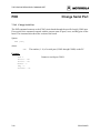
Change Serial Port (POD) .................................................................................... 7-60
Set Port A Output Latches (PORTA) .................................................................. 7-61
Set Port B Output Latches (PORTB)................................................................... 7-62
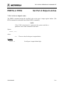
Start Programmer (PROGRAM) ......................................................................... 7-63
The Pick Window ................................................................................................ 7-63
Status Window...................................................................................................... 7-63
705JICSUM/D
ix
CONTENTS
CHAPTER 7
7.3.55
7.3.56
7.3.57
7.3.58
7.3.59
7.3.60
7.3.61
7.3.62
7.3.63
7.3.64
7.3.65
7.3.66
7.3.67
7.3.68
7.3.69
7.3.70
7.3.71
7.3.72
7.3.73
7.3.74
7.3.75
7.3.76
7.3.77
7.3.78
7.3.79
7.3.80
7.3.81
THE ICS05JW DEBUGGING COMMAND SET (CONTINUED)
File Window ......................................................................................................... 7-63
Show Registers (REG) ......................................................................................... 7-65
Place Comment in Batch/Macro File (REM)....................................................... 7-66
Simulate Processor Reset (RESET)..................................................................... 7-67
Reset and Restart MCU (RESETGO) ................................................................. 7-68
Save Desktop Settings (SAVEDESK) ................................................................. 7-69
Display Breakpoint Window (SHOWBREAKS)................................................ 7-70
Display Code at Address (SHOWCODE)........................................................... 7-71
Show Information in Map File (SHOWMAP) .................................................... 7-72
Show Code from PC Address Value (SHOWPC) ............................................... 7-73
Display Trace Window (SHOWTRACE)........................................................... 7-74
Set Stack Pointer (SP) .......................................................................................... 7-75
Execute Source Step(s) (SS)................................................................................. 7-76
Execute Single Step(s) (ST, STEP) ..................................................................... 7-77
Show Stack Window (STACK) ........................................................................... 7-78
Step Forever (STEPFOR).................................................................................... 7-79
Step Until Address (STEPTIL) ........................................................................... 7-80
View or Create Symbol (SYMBOL) ................................................................... 7-81
Show Available System Memory (SYSINFO) .................................................... 7-82
Enable/Disable Tracing (TRACE)....................................................................... 7-83
Upload S Record to Screen (UPLOAD_SREC).................................................. 7-84
Display Variable VAR ......................................................................................... 7-85
Display Software Version (VER)......................................................................... 7-86
Wait for n Cycles (WAIT) ................................................................................... 7-87
Display Symbol Value (WHEREIS) ................................................................... 7-88
Set X Register Value (X)...................................................................................... 7-89
Set/Clear Zero Bit (Z)........................................................................................... 7-90
CHAPTER 8
EXAMPLE PROJECT
8.1 Overview............................................................................................................................. 8-1
8.2 Setting Up a Sample Project ............................................................................................... 8-1
8.2.1
Setup the Environment ........................................................................................... 8-2
8.2.2
Create the Source Files ........................................................................................... 8-3
8.2.3
Assemble the Project .............................................................................................. 8-4
x
705JICSUM/D
CONTENTS
APPENDIX A
A.1
A.2
A.3
A.4
A.5
S-RECORD INFORMATION
Overview.............................................................................................................................A-1
S-Record Content ...............................................................................................................A-1
S-Record Types .................................................................................................................A-2
S-Record Creation .............................................................................................................A-3
S-Record Example .............................................................................................................A-3
A.5.1
The S0 Header Record ...........................................................................................A-4
A.5.2
The First S1 Record ...............................................................................................A-5
A.5.3
The S9 Termination Record ...................................................................................A-6
A.5.4
ASCII Characters ...................................................................................................A-6
APPENDIX B
M68HC705JICS IN-CIRCUIT SIMULATOR KIT SUPPORT
INFORMATION
B.1 Overview.............................................................................................................................B-1
B.2 Functional Description of The Kit .....................................................................................B-1
B.2.1
The Emulator .........................................................................................................B-1
B.2.2
Programming .........................................................................................................B-2
B.3 Troubleshooting The Quick Start ......................................................................................B-3
B.4 Troubleshooting The Programmer .....................................................................................B-5
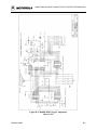
B.5 Logic Diagram and Parts List ............................................................................................B-5
Glossary ........................................................................................................................... Glossary-1
Index ..................................................................................................................................... Index-1
FIGURES
1-1
1-2
2-1
2-2
2-3
2-4
3-1
4-1
4-2
4-3
WinIDE Environment Settings Dialog ............................................................................ 1-6
WinIDE Environment Settings Dialog Assembler/Compiler Tab................................... 1-7
M68HC705JICS Circuit Board (Pod).............................................................................. 2-2
Jumper Headers J3 through J8......................................................................................... 2-3
Jumper Headers J9 through J14....................................................................................... 2-3
Jumper Header J17 Factory Configuration...................................................................... 2-3
ICS05JW Can’t Contact Board Dialog............................................................................ 3-4
WinIDE Window Components........................................................................................ 4-1
WinIDE Status Bar .......................................................................................................... 4-3
Edit Shortcut Menu.......................................................................................................... 4-5
705JICSUM/D
xi
CONTENTS
FIGURES (continued)
4-4
4-5
4-6
4-7
4-8
4-9
Marker Sub-menu ............................................................................................................ 4-6
WinIDE Toolbar .............................................................................................................. 4-7
File Menu....................................................................................................................... 4-10
Open File Dialog ........................................................................................................... 4-11
Print Dialog ................................................................................................................... 4-12
Edit Menu ...................................................................................................................... 4-13
4-10
4-11
4-12
4-13
4-14
4-15
4-16
4-17
4-18
4-19
4-20
4-21
4-22
4-23
4-24
4-25
4-26
4-27
4-28
5-1
5-2
5-3
6-1
6-2
6-3
6-4
6-5
Environment Menu ........................................................................................................ 4-16
Specify project file to open Dialog................................................................................. 4-17
Specify project file to save Dialog ................................................................................. 4-17
Environment Settings Dialog General Environment Tab .............................................. 4-18
Environment Settings Dialog: General Editor Tab ....................................................... 4-20
Environment Settings Dialog: Assembler/Compiler Tab............................................... 4-22
Error Format List ........................................................................................................... 4-25
Environment Settings Dialog: EXE 1 (Debugger) and EXE 2 (Programmer) Tabs...... 4-26
Setup Fonts Dialog ........................................................................................................ 4-28
Search Menu .................................................................................................................. 4-29
Find Dialog.................................................................................................................... 4-30
Replace Dialog............................................................................................................... 4-31
Go To Line Number Dialog ........................................................................................... 4-32
The Window Menu ........................................................................................................ 4-32
WinIDE with Subordinate Windows Cascaded............................................................. 4-33
WinIDE with Subordinate Windows Tiled.................................................................... 4-33
WinIDE with One Source Window Displayed.............................................................. 4-34
The WinIDE Editor with Subordinate Windows Minimized ........................................ 4-34
Split Pointer and Bar...................................................................................................... 4-35
WinIDE with CASM05W Assembler Window Displayed ............................................. 5-2
Windows 95 Program Item Property Sheet ..................................................................... 5-3
CASM05W for Windows Assembler Parameters ........................................................... 5-5
Can’t Contact Board Dialog............................................................................................ 6-6
The ICS05JW Windows Default Positions ..................................................................... 6-7
Code Window in Disassembly Mode with Breakpoint Toggled ..................................... 6-8
Code Window Shortcut Menu ......................................................................................... 6-8
Window Base Address Dialog.......................................................................................... 6-9
xii
705JICSUM/D
CONTENTS
FIGURES (continued)
6-6
6-7
6-8
6-9
6-10
6-11
6-12
6-13
6-14
Variables Window with Shortcut Menu ........................................................................ 6-10
Add Variable Dialog ...................................................................................................... 6-11
Memory Window with Shortcut Menu.......................................................................... 6-13
Status Window............................................................................................................... 6-14
Results of Entering the LF Command in the Status Window........................................ 6-15
Specify Output LOG File! Dialog .................................................................................. 6-15
The Logfile Already Exists Message.............................................................................. 6-16
CPU Window with Shortcut Menu................................................................................ 6-17
The Change CCR Dialog ............................................................................................... 6-17
6-15
6-16
6-17
6-18
6-19
6-20
6-21
6-22
6-23
6-24
6-25
6-26
6-27
6-28
6-29
6-30
6-31
6-32
6-33
6-34
6-35
7-1
7-2
Chip Window................................................................................................................. 6-18
Cycles Window.............................................................................................................. 6-19
Stack Window................................................................................................................ 6-20
Trace Window ............................................................................................................... 6-21
Breakpoint Window with Shortcut Menu...................................................................... 6-22
Edit Breakpoint Dialog .................................................................................................. 6-22
PROG05P9 Programmer Pick Window......................................................................... 6-24
Programmer Files Window............................................................................................ 6-24
The Register Block Window ......................................................................................... 6-25
The WinReg Window with Typical Register File Information ..................................... 6-25
WinIDE Toolbar ............................................................................................................ 6-26
File Menu....................................................................................................................... 6-29
Specify S19 File to Load Dialog .................................................................................... 6-30
Specify MACRO File to Execute Dialog........................................................................ 6-31
Specify MACRO File to Record Dialog ......................................................................... 6-31
Specify Output LOG File Dialog ................................................................................... 6-32
Logfile Already Exists Dialog........................................................................................ 6-32
A Sample Output Log File............................................................................................. 6-33
ICS05JW Execute Menu................................................................................................ 6-34
Window Menu ............................................................................................................... 6-35
Change Window Colors Dialog ..................................................................................... 6-36
Assembly Window Showing ASM Command .............................................................. 7-10
Modify Memory Dialog.................................................................................................. 7-56
705JICSUM/D
xiii
CONTENTS
FIGURES (continued)
7-3
8-1
B-1
B-2
PROG05P Programmer Pick Window........................................................................... 7-64
CASM05W Window ....................................................................................................... 8-4
M68HC705J1 Logic Components (Sheet 1 of 2) ............................................................B-7
M68HC705J1 Logic Components (Sheet 2 of 2) ............................................................B-9
TABLES
1-1
3-1
4-1
4-2
45-1
5-2
5-3
5-4
5-5
5-6
6-1
6-2
6-3
7-1
7-2
7-3
A-1
A-2
A-3
A-4
A-5
A-6
B-1
xiv
M68HC705JICS Specifications....................................................................................... 1-4
The ICS05JW Software Files .......................................................................................... 3-3
WinIDE Toolbar Buttons................................................................................................. 4-7
WinIDE Menus and Options Summary........................................................................... 4-8
Change Base Prefixes/Suffixes........................................................................................ 5-8
Assembler Directives and Conditional Assembler Directives....................................... 5-10
Listing Directives........................................................................................................... 5-13
Listing File Fields .......................................................................................................... 5-14
Pseudo Operations Allowed by the CASM05W ........................................................... 5-16
Assembler Error Messages ............................................................................................ 5-18
Base Prefixes and Suffixes ............................................................................................ 6-12
ICS05JW Toolbar Buttons............................................................................................. 6-27
ICS05JW Menus and Options Summary....................................................................... 6-28
Argument Types .............................................................................................................. 7-2
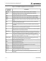
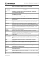
ICS05JW Command Overview ....................................................................................... 7-3
Programming Commands .............................................................................................. 7-65
S-Record Fields ...............................................................................................................A-1
S-Record Field Contents..................................................................................................A-2
S-Record Types ...............................................................................................................A-3
S0 Header Record ............................................................................................................A-4
S1 Header Record ............................................................................................................A-5
S-9 Header Record...........................................................................................................A-6
M68HC705JICS Parts List ............................................................................................B-11
705JICSUM/D
INTRODUCTION
CHAPTER 1
INTRODUCTION
1.1 OVERVIEW
This chapter is an overview of the M68HC705JICS In-Circuit Simulator Kit components and a
Quick Start guide to setting up a development project.
The Motorola M68HC705JICS In-Circuit Simulator Kit is a development toolkit for designers
who develop and debug target systems that incorporate the M68HC705JICS Microcontroller
Unit (MCU) devices. The toolkit contains all of the hardware and software you need to develop
and simulate source code for and program Motorola M68HC05J family microcontrollers.
Together, the M68HC705JICS printed circuit board (pod) and the ICS05JW software form a
complete simulator and non-real-time I/O emulator for simulating, programming, and debugging
code for a M68HC705J1 device. When you connect the pod to your host computer and optional
target hardware, you can use the actual inputs and outputs of the target system during simulation
of code. You can also use the ICS05JW software to edit and assemble code in standalone mode,
without pod input/output.
Use the M68HC705JICS toolkit with any IBM-Windows 3.x or Windows 95-based computer
with a serial port.
705JICSUM/D
1-1
INTRODUCTION
1.2 TOOLKIT COMPONENTS
The complete M68HC705JICS toolkit contains:
•
The M68HC705JICS in-circuit simulator pod.
•
A sample MC68HC705J1 EPROM MCU.
•
A 28-lead header target emulation cable.
•
Windows-optimized software components, collectively referred to as ICS05JW
software, and consisting of:
WINIDE.EXE, the integrated development environment (IDE) software
interface to your target system for editing and performing software or incircuit simulation.
CASM05W.EXE, the CASM05W command-line cross-assembler.
ICS05JW.EXE, the in-circuit/standalone
M68HC705JICS target MCU.
•
simulator
software
for
the
Documentation:
The M68HC705JICS In-Circuit Simulator User's Manual.
Technical literature, including Understanding Small Microcontrollers, an
introductory guide to understanding and using Motorola MC68HC05 family
microcontrollers.
1-2
705JICSUM/D
INTRODUCTION
1.3 HARDWARE AND SOFTWARE REQUIREMENTS
The ICS05JW software requires this minimum hardware and software configuration:
•
An IBM-compatible host computer running Windows 3.x or Windows 95 operating
system.
•
Approximately 640 Kb of memory (RAM) and 2 Mb free drive space
•
A serial port for communications between the M68HC705JICS and the host
computer.
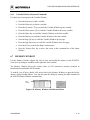
1.4 TOOLKIT FEATURES
The M68HC705JICS toolkit is a low-cost development system that supports in-circuit
simulation. Its features include:
•
Software and in-circuit simulation of the M68HC705J1 MCU
•
Ability to program MC68HC705J1 EPROM microcontrollers
•
Communication with the host computer via a serial port
•
ICS05JW software, including editor, assembler, and assembly source-level simulator
•
64 instruction breakpoints
•
SCRIPT command for automatic execution of a sequence of commands
•
Emulation cable for connection to the target system
•
On-screen, context-sensitive Windows Help
•
CHIPINFO command: M68HC705JICS pod memory-map, vector, register, and pinout information
•
Software responds to both mouse and keyboard controls
705JICSUM/D
1-3
INTRODUCTION
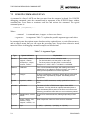
1.5 SPECIFICATIONS
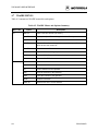
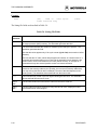
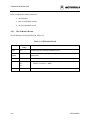
Table 1-1 summarizes the M68HC705JICS hardware specifications.
Table 1-1. M68HC705JICS Specifications
Characteristic
Specification
Temperature:
Operating
Storage
+25°C
-40° to +85° C
Relative humidity
0 to 95% (non-condensing)
Power requirement
+9Vdc @ 0.2 A (maximum)
(from included wall transformer)
Dimensions
3.6 x 6.1 in. (91 x 154 mm)
1.6 ABOUT THIS USER’S MANUAL
This manual covers the ICS05JW software, hardware, and reference information as follows:
1-4
•
Chapter 2: Pod Installation
•
Chapter 3: Loading and Initializing the ICS05JW Software
•
Chapter 4: The WinIDE User Interface
•
Chapter 5: The ICS05JW In-Circuit Simulator User Interface
•
Chapter 6: The CASM05W Assembler
•
Chapter 7: The ICS05JW Debugging Command Set
•
Chapter 8: Example Project
•
Appendix A: S-Record Information
•
Appendix B: ICS05JW Support Information
•
Glossary
•
Index
705JICSUM/D
INTRODUCTION
NOTE
The procedural instructions in this user's manual assume that you
are familiar with the Windows interface and selection procedures.
Figures in this manual show ICS05JW windows and dialog boxes
as they appear in the Windows 95 environment.
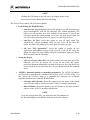
1.7 QUICK START INSTRUCTIONS
The following instructions summarize the hardware and software installation instructions of
Chapters 2 and 3.
If you are experienced in installing Motorola or other development tools, follow these steps:
•
Install the ICS05JW software: follow the instructions on the diskette label to run
the ICS05JW Setup program. During installation, follow the instructions in the
installation wizard: choose the Typical Install option to install the files to your hard
disk, or choose the Compact Install option to copy the files onto another diskette.
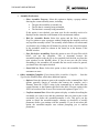
•
Connect the M68HC705JICS pod: connect the M68HC705JICS pod to the host
computer’s serial port using the included cable. Plug the cable into the P2 pod
connector.
•
Supply power to the M68HC705JICS pod: connect the wall-mounted transformer’s
circular connector to the P1 connector on the left side of the pod, next to the serial
connector. Turn pod switch S1 ON to apply power to the pod.
•
Start the ICS05JW simulator and test the pod connection: Double click the
ICS05JW icon. In the Status Window command line, enter the POD command using
the COM port to which the pod is connected as the argument. A message will tell you
the status of the connection between the host computer's communication port and the
pod.
•
Start the WinIDE software and open the project files: Double click the WinIDE
icon. From the WinIDE Environment menu, choose the Open Project option, and
choose a project file from the Specify project file to open dialog. If no project file
exists, choose the New option from the File menu to create a new project file.
Paragraph 8.3 gives additional information about setting up a sample project.
705JICSUM/D
1-5
INTRODUCTION
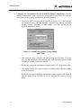
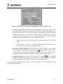
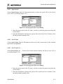
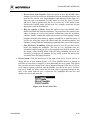
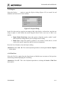
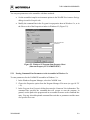
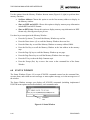
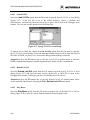
•
Configure the environment for the ICS05JW software components: from the
WinIDE Environment menu, choose the Setup Environment option to open the
Environment Settings dialog and make the following changes:
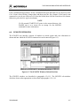
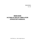
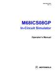
Click on the EXE1 Debugger tab to bring the tab (Figure 1-1) to the front. Set
the executable type, path and filename, command line options (including
optional switches, filenames, or port settings), and other options for the
ICS05JW simulator software.
Figure 1-1. WinIDE Environment Settings Dialog
EXE1 Tab
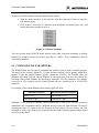
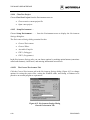
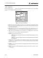
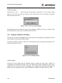
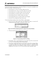
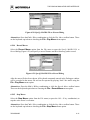
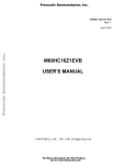
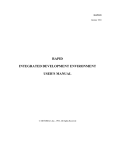
Click on the Assembler/Compiler tab label to bring the tab (Figure 1-2) to the
front. Set the executable path and filename, type, and other options for the
CASM05W (or other) assembler software.
If necessary, change the programmer settings in the EXE2 (Programmer) tab.
Click on the General Environment and General Editor tabs and make changes
in each as necessary.
When you have specified all the environment settings, press the OK button to
save the changes in the WINIDE.INI file and close the Environment Settings
dialog.
1-6
705JICSUM/D
INTRODUCTION
Figure 1-2. WinIDE Environment Settings Dialog Assembler/Compiler Tab
•
Create a project file: The desktop and environment settings you make in the
Environment Settings dialog are stored in the WINIDE.INI file and read each time you
start the WinIDE editor. You may also choose to save project-specific desktop and
environment settings in a project file (*.PPF) which is read when you open the
project, allowing you to save and use a general environment as well as custom
environments for individual projects. To create the project file:
Specify the project-specific desktop and environment settings in the WinIDE
editor.
Choose the Save Project As . . . option from the WinIDE Environment menu
to name and save the project to a directory folder.
•
Run the ICS05JW simulator: With a project or source file open in the WinIDE
on the WinIDE toolbar to move
main window, click the Debugger (EXE1) button
to the ICS05JW simulator and debug the contents of the active source window.
Additional information about the ICS05JW simulator can be found in Chapter 5.
•
Assemble the code: Press the Assemble/Compile File button
on the WinIDE
toolbar to assemble the source code in the active WinIDE window. Additional
information about the CASM05W assembler can be found in Chapter 6.
If you experience problems with the Quick Start procedures, refer to paragraph B.3 for
troubleshooting instructions.
705JICSUM/D
1-7
INTRODUCTION
1-8
705JICSUM/D
POD INSTALLATION
CHAPTER 2
POD INSTALLATION
2.1 OVERVIEW
This chapter explains how to install the hardware components of the ICS05JW on your host
computer in both interactive and standalone modes.
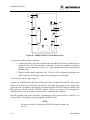
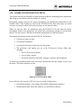
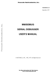
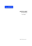
2.2 INSTALLING THE M68HC705JICS POD
When the M68HC705JICS pod (Figure 2-1) is connected to the serial port of a host computer,
you can use the actual inputs and outputs of your target system during simulation of your source
code. When the pod is not connected to the host computer, you can use the ICS05JW simulator
software as a standalone simulator/debugger.
The M68HC705JICS pod is a single printed circuit board. Before beginning to install the pod,
locate these pod components:
•
9-pin RS-232 serial connector P2
•
9-volt Input Circular connector P1
•
20-pin DIP socket U5
•
Pod Power On switch S1
•
Programming (VPP) Power Switch S2
•
Microprocessor Reset Switch S3
705JICSUM/D
2-1
POD INSTALLATION
S1
P1
P2
LED1
S2
S4
S3
J1
J2
U4
U5
J17
U6
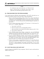
Figure 2-1. M68HC705JICS Circuit Board (Pod)
To connect the pod to the host computer:
1. Connect the pod to your host computer using the DB9 serial cable to connect the pod
connector P2 to the host computer's serial port. If the host computer's serial port
requires a 25-pin connector, use the 9- to 25-pin adapter between the serial port and
the DB9 cable.
2. Plug the round output connector of the 120Vac-to-9Vdc wall-plug transformer into
the P1 connector on the pod to supply the operating power for the pod.
To connect the pod to a target system:
Connect the 20-lead header cable between the pod socket U5 and the 20-pin DIP socket of the
target system. When you connect the JICS pod to your target system and power up, the target
system provides all inputs to and accepts all outputs from the ICS05JW software. RESET and
IRQ lines also interact with the ICS05JW software. When you execute a GO command, the
simulator does not run in real time, because the host computer is the simulator.
Note the position of the power switch S1, programming (VPP) power switch S2, and MCU U4
reset switch S3. Switch S4 is for experimenting with the PA0 line.
NOTE
Do not press switch S3 unless the ICS05JW software prompts you
to do so.
2-2
705JICSUM/D
POD INSTALLATION
Jumper header J1 enables switch S4. A fabricated jumper in header J1 connects switch S4 to the
PA0 pin of the MCU. To disconnect switch S4, remove the jumper from the header.
Jumper header J2 enables LED1. A fabricated jumper in this header connects LED1 to the PA7
pin of the MCU. To disconnect LED1, remove the jumper from this header.
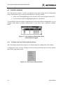
Jumper headers J3 through J8 (Figure 2-2) are compensating pull-downs for the port B pins. The
M68HC705JICS pod uses an MC68HSC705C9A MCU to emulate an MC705HCJ1 MCU.
Unlike the MC705HCJ1, the MC68HSC705C9A does not have programmable pull-downs.
Jumper headers J3 through J8 compensate manually: a fabricated jumper in any of these headers
connects the corresponding port pin to a pull-down resistor, pulling the signal low.
PB5
PB4
PB3
PB2
PB1
PB0
J3
J4
J5
J6
J7
J8
Figure 2-2. Jumper Headers J3 through J8
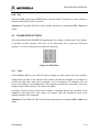
Jumper headers J9 through J16 (Figure 2-3) are compensating pull-downs for the port A pins.
Fabricated jumpers in any of these headers have the same function as jumpers in headers J3
through J8, but apply to port A pins instead of port B pins.
PA7
PA6
PA5
PA4
PA3
PA2
PA1
PA0
J9
J10
J11
J12
J13
J14
J15
J16
Figure 2-3. Jumper Headers J9 through J16
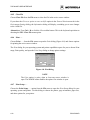
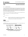
Jumper header J17 sets the baud rate for communication with the host computer. Figure 2-4
shows the factory configuration: the fabricated jumper between pins 1 and 2 selects 115.2
kilohertz.
19.2k
115.2k
J17
1
2
3
Figure 2-4. Jumper Header J17 Factory Configuration
705JICSUM/D
2-3
POD INSTALLATION
To change to the alternative rate of 19.2 kilohertz:
1. Position the J17 jumper between pins 2 and 3.
2. Press the S3 switch to reset the pod.
3. In the WinIDE Environment Settings dialog EXE1 (Debugger) tab, include the
/b19200 parameter value in the EXE Path textbox or choose the /b19200 option when
the ICS05JW starts up. For information about entering executable path parameters,
see paragraph 4.10.5.4.
2-4
705JICSUM/D
INSTALLING AND INITIALIZING THE ICS05JW SOFTWARE
CHAPTER 3
INSTALLING AND INITIALIZING THE ICS05JW SOFTWARE
3.1 OVERVIEW
This chapter how to install and initialize the ICS05JW software.
3.2 THE ICS05JW SOFTWARE COMPONENTS
The ICS05JW software consists of the following components:
3.2.1
•
WINIDE.EXE: the Windows Integrated Development Environment editor
•
CASM05W.EXE: the 68HC05 Cross Assembler
•
ICS05JW.EXE: the in-circuit Simulator, optimized for the HC05J-family Motorola
microcontrollers
WinIDE
The WinIDE editor is a text editing application that lets you use several different programs from
within a single development environment. Use the WinIDE editor to edit source code, launch a
variety of compatible assemblers, compilers, debuggers, or programmers, and configure the
environment to read and display errors from such programs.
If you select error detection options in the Environment Settings dialog, the WinIDE editor will
highlight errors in the source code, and display the error messages from the compiler or
assembler in the editor.
To debug source code in the WinIDE code window, load compatible source-level map files. You
can configure the CASM05W to produce such map files as an output.
Because the WinIDE editor is modular, you may, for example, choose to substitute a third party
C-compiler or other assembler for the CASM05W cross assembler provided in the toolkit.
705JICSUM/D
3-1
INSTALLING AND INITIALIZING THE ICS05JW SOFTWARE
3.2.2
CASM05W
The CASM05W is a cross assembler that creates Motorola S19 object files and MAP files from
assembly files containing 68HC05 instructions.
The CASM05W assembler has the same functionality as the DOS version of the assembler, but
has been optimized to take advantage of the Windows graphical environment. Using the
assembler in conjunction with the WinIDE editor, you can edit standard ASCII files (such as the
.ASM assembly files), and use menu options and toolbar buttons to call other customized
assemblers, compilers, or debuggers. The resulting environment lets you assemble files,
download and test them, all without leaving the WinIDE editing environment.
Paragraph 5-5 gives additional information about assembler options and how to use them.
3.2.3
ICS05JW
The ICS05JW is a simulator for the HC705J1 microcontroller that can get inputs and outputs
(I/O) for the device when the external M68HC705JICS pod is attached to the host computer. If
you want to use I/O from your own target board, you can attach the pod to your board through
the extension cable that comes with the toolkit. You can also program the HC05J1 device using
the M68HC705JICS pod and the ICS05JW simulator software.
You can start or move to the ICS05JW in-circuit simulator software from the WinIDE editor.
The ICS05JW software can also be started using standard Windows techniques and run
independently of the WinIDE editor.
The ICS05JW simulator accepts standard Motorola S19 object code files as input for object code
simulation and debugging. If you are using a third party assembly- or C-language compiler, the
compiler must be capable of producing source-level map files to allow source-level debugging.
3-2
705JICSUM/D
INSTALLING AND INITIALIZING THE ICS05JW SOFTWARE
3.3 INSTALLING THE ICS05JW SOFTWARE
The ICS05JW software is contained on a single 3.5″ diskette containing a setup program that
automatically installs the software on your hard drive.
3.3.1
To Install the ICS05JW Software
To install the software on your host computer’s hard drive:
•
Insert the ICS05JW diskette into the 3.5-inch disk drive.
For Windows 3.x: in the Program Manager, select Run from the File menu.
For Windows 95: from the Start Menu, select the Run option.
•
In the Run dialog, enter Setup (or click the Browse button to select a different drive
and/or directory) and press OK.
•
In the ICS05JW Microsoft Setup Wizard, follow the instructions that appear on the
screen.
NOTE
In the Setup wizard, select the Typical Installation option to install
the files to your hard disk, or choose the Compact Installation
option to copy the files to another diskette.
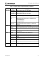
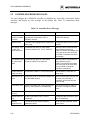
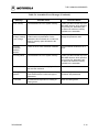
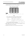
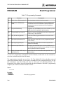
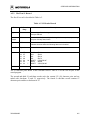
Table 3-1 describes the system files and directories required to control the ICS05JW system.
Table 3- 1. The ICS05JW Software Files
Directory
Filename
Description
Casmw
casm05w.exe
Windows Cross Assembler for the 68HC05
ICS05JW
ics05jw.exe
Windows In-Circuit Simulator
WinIDE
winide.exe
Winide.hlp
Windows integrated Development Environment (WinIDE) program file
Help for WinIDE
705JICSUM/D
3-3
INSTALLING AND INITIALIZING THE ICS05JW SOFTWARE
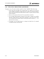
3.3.2
To Start the ICS05JW Software
Depending on the operating system you are using, choose the appropriate method for starting the
WinIDE software:
•
From the Windows 3.x Program Manager, double-click the WinIDE and/or ICS05JW
icon(s).
•
From the Windows 95 Start Menu, select the WinIDE and/or ICS05JW icon(s).
You can start the ICS05JW simulator alone or from within the WinIDE.
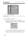
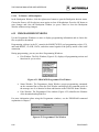
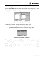
3.3.3
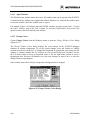
ICS Communication
When you double-click the ICS05JW icon, the software attempts to communicate with the pod
using the specified COM port, baud rate, and default parameters. When the software connects to
the pod, the Status Bar contains the message, Contact with pod established.
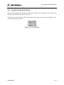
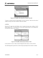
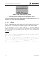
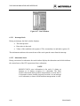
If the pod is not installed, or the ICS05JW software cannot establish communications with the
pod through the specified COM port, the Can’t Contact Board dialog appears (Figure 3-1), with
options for changing the COM port or baud rate and retrying the connection, or choosing to run
the simulator in standalone mode (with no input or output from the pod).
Figure 3-1. ICS05JW Can't Contact Board Dialog
If you receive communication error messages, reduce the baud rate on the host computer. If
communication errors persist, exit from the ICS05JW simulator and disable disk caching
(SMARTDRV.EXE) on the host computer.
NOTE
The COM port assignment defaults to COM 1 unless you specify
another port in the startup command.
3-4
705JICSUM/D
THE WinIDE USER INTERFACE
CHAPTER 4
THE WinIDE USER INTERFACE
4.1 OVERVIEW
This chapter is an overview of the WinIDE windows, menus, toolbars, dialogs, options, and
procedures for using each.
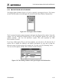
4.2 THE WINDOWS INTEGRATED DEVELOPMENT ENVIRONMENT
The Windows Integrated Development Environment (the WinIDE editor) is a graphical interface
for editing, compiling, assembling, and debugging source code for embedded systems using the
In-Circuit Simulator for the ICS05JW.
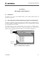
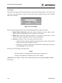
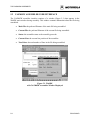
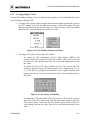
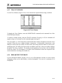
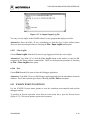
The WinIDE interface consists of standard Windows title and menu bars, a WinIDE toolbar, a
main window (containing any open source or project file windows), and a status bar. The
WinIDE window components are labeled in Figure 4-1 and described in paragraph 4.3.2.
Title Bar
Menu Bar
Toolbar
Source Windows
Main Window
Status Bar
Figure 4-1. WinIDE Window Components
705JICSUM/D
4-1
THE WinIDE USER INTERFACE
4.3 WinIDE WINDOWS
4.3.1
Main Window Functions
When you first start the WinIDE editor, the main window opens without any source or project
files. As you open or create source files or a project, they appear as subordinate windows in the
main window. You can move, size, and arrange subordinate windows using standard Windows
techniques and the WinIDE Window menu options.
Use the WinIDE main window to:
4.3.2
•
Open, create, edit, save, or print source (*.ASM, *.LST, *.MAP, and *.S19) or
project (*.PPF) file.
•
Configure the desktop and environment settings for the editor, assembler, compiler,
debugger, and other programs.
•
Launch the in-circuit simulator, compiler, debugger, or another program.
Main Window Components
Figure 4-1 shows how the WinIDE main window might look during a typical editing project, and
labels the standard window components:
•
Title Bar: The title bar appears at the top edge of the main window and contains:
The application title
The name of the target microcomputer application for which you are editing
source code
The object file or files, if any (usually truncated)
Windows control buttons for closing, minimizing or maximizing the window
4-2
•
Menu Bar: The menu bar appears immediately below the title bar and contains the
names of the WinIDE menus.
•
Toolbar: The WinIDE toolbar appears just below the menu bar and contains shortcut
buttons for frequently used menu options.
•
Main Window: The main window area is the inside portion of the main window
which contains the open subordinate windows that you can resize, reposition,
minimize, or maximize using standard Windows techniques or Window menu
options.
705JICSUM/D
THE WinIDE USER INTERFACE
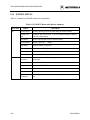
•
Status Bar: The status bar (Figure 4-2) appears along the bottom edge of the main
window and contains a number of fields (depending on the project) that show
Source-file line and column numbers of the blinking insertion point cursor
System status or progress of the current window; for example, when the
window is edited, the status will be Modified
Total number of lines in the active window
Top: the current line position in the file of the top of the active window
Bytes: displays the total number of bytes in the active window
Insert/Overwrite mode: indicates the current typing mode
The status fields expand and contract as client area contents change and files become
active.
Figure 4-2. WinIDE Status Bar
4.4 GETTING STARTED
4.4.1
Prerequisites for Starting the WinIDE Editor
Before you can start the WinIDE editor, the Windows operating environment must be running
and the ICS05JW software must be installed in the host computer.
Remember also, that for the ICS05JW to run in simulation mode, the asynchronous
communications cable must connect the M68HC705JICS pod on the platform board to the host
computer, and the power to the M68HC705JICS pod must be on.
4.4.2
To Start the WinIDE Editor
To start the editor, select the WinIDE icon by double-clicking the ICS05JW Program Group icon
in the Windows 3.1 Program Manager or by selecting the icon from the Windows 95 Start menu.
705JICSUM/D
4-3
THE WinIDE USER INTERFACE
4.4.3
To Open Source Files
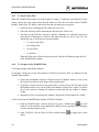
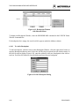
When the WinIDE editor opens, the main window is empty. To build the environment for your
project, choose the Open option from the File menu (or click the File button on the WinIDE
toolbar). In the Open File dialog, choose the files that will make up your project:
1. Select the drive containing the files from the Drives list.
2. Select the directory folder containing the files from the Folders list.
3. You may use the Filename text box to specify a filename or a wildcard extension to
filter the list of filenames (or choose a file type from the List files of type list). The
default file type is .ASM, but you can also choose:
*.c ( source code files)
*.lst (listing files)
*.txt (text files)
*.* (all files)
When all of the project files have been selected, click the OK button to open the files
in the WinIDE main window.
4.4.4
To Navigate in the WinIDE Editor
To navigate among subordinate windows:
To navigate among the several sub-windows in which your project files are displayed in the
WinIDE main window:
•
Choose the subordinate window's filename from the Window menu or click on the
file's title bar to bring it to the front of the cascaded stack.
•
If you have a large screen or a few project files, you may choose the Tile option from
the Window menu to lay out all of the sub-windows so that all are visible, or choose
the Cascade option to arrange all windows so that only the top window is entirely
visible.
•
Regardless of how you arrange the windows, the title bar of all windows are visible.
To move between the WinIDE editor and the ICS05JW simulator:
4-4
•
From the WinIDE editor, click the External Program 1 toolbar button
to switch
to the in-circuit simulator or the application which you have specified as the debugger
or other external program to use.
•
From ICS05JW, click the Back to Editor toolbar button
editor.
to toggle back to the
705JICSUM/D
THE WinIDE USER INTERFACE
4.4.5
Using Markers
Markers provide a convenient way to mark multiple points in a file for navigating between
frequently visited locations while you are editing. You can set as many as 10 markers in source
files in the WinIDE editor. A marker appears in the file as a small button labeled with the marker
number.
When you save the project, the WinIDE editor saves the markers for all open edit files as well, so
that when you open the project again, the markers are still set.
To set a marker anywhere in the file:
1. Place the cursor on the line where you want the marker to be.
2. Press CNTL + SHIFT + N, where N is a value from 0 to 9 indicating the marker
number. A marker appears at the far left of the line.
To move to a marker, press CNTL + N, where N is denotes a marker number between 0 and 9.
This feature is useful if you are editing a large file.
Markers can also be set, changed, navigated to, or cleared using options on the Edit shortcut
menu (Figure 4-3). Open the Edit shortcut menu by clicking the right mouse button in any edit
window.
Figure 4-3. Edit Shortcut Menu
To set or clear a marker using the Edit shortcut menu options:
1. With the cursor in any editing window, click the right mouse button to open the
shortcut menu.
2. Position the cursor on the line where the marker should appear. Click the right mouse
button to display the shortcut menu.
3. Click the Toggle Marker 0-9 option to open the list of markers.
4. Click once on the marker to toggle. When the marker number is checked, it is toggled
on; when the marker number is unchecked, it is toggled off.
705JICSUM/D
4-5
THE WinIDE USER INTERFACE
To move to a marker number using the shortcut menu options:
1. With the cursor anywhere in the edit file, click the right mouse button to open the
Edit shortcut menu .
2. Click on the Go To Marker 0-9 option to open the Marker sub-menu (Figure 4-4), and
choose the marker number to move to.
Figure 4-4. Marker Sub-menu
You can execute many ICS05JW menu options using either keyboard commands or toolbar
buttons. For example, to move to a marker, press the Ctrl + Shift + N key combination, where N
is the marker number).
4.5 COMMAND LINE PARAMETERS
The WinIDE editor lets you specify command line options to pass to each executable program.
The name of the currently edited file, or some derivative thereof, can be passed within these
options. To pass the current filename, specify a parameter %FILE%. The WinIDE editor will
substitute this string with the current filename at execution time. You may also change the
extension of the passed filename, by specifying it within the %FILE% parameter. For example,
to specify an .S19 extension on the current filename the user would specify a %FILE.S19%
parameter.
For example, if the current filename being edited is MYPDA.ASM:
Parameters specified
Parameters passed to program
%FILE% S L D
MYPDA.ASM S L D
%FILE.S19% 1 @2
MYPDA.S19 1 @2
Although it is by default the currently edited filename that is used in the %FILE% parameter
substitution, the environment can be configured always to pass the same filename. Do this by
checking the Main File option in the Environment Settings dialog's General Options tab. This
technique is useful if you want to pass a specific filename to the external program without regard
to what is being edited.
4-6
705JICSUM/D
THE WinIDE USER INTERFACE
4.6 WinIDE TOOLBAR
The WinIDE Toolbar (Figure 4-5) provides a number of convenient shortcut buttons that
duplicate the function of the most frequently used menu options. A tooltip or label pops up when
the mouse button lingers over a toolbar button, identifying the button's function.
Figure 4-5. WinIDE Toolbar
Table 4-1 identifies and describes the WinIDE toolbar buttons.
Table 4-1. WinIDE Toolbar Buttons
Button Label
Icon
Button Function
External Program 1 (Debugger)
Call the External Program 1 (Debugger or ICS) specified in
the Environment Settings dialog's EXE 1 (Debugger) tab;
this could be the debugger (by default), the ICS or other
external program, i.e., third party assembler, debugger, or
compiler.
External Program 2
Call the External Program 2 as specified in the Environment
Settings dialog's EXE 2 (Programmer) tab
Assemble/Compile File
Assemble or compile the active source window .
Cut
Cut the selected text from the active source window (this
button is a shortcut for the Edit - Cut menu option).
Copy
Copy the selected text in the active source window to the
Windows clipboard (this button is a shortcut for the Edit Copy menu option).
Paste
Paste the contents of the Windows clipboard at the
insertion-point location in the active source window (this
button is a shortcut for the Edit - Paste menu option).
Open File
Close the active source window (this button is a shortcut for
the File - Open menu option).
Save File
Save the file in the active source window (this button is a
shortcut for the File - Save menu option).
Save Project (All Files & Setup)
Save the active project (this button is a shortcut for the
Environment - Save Project As . . . menu option).
Close File
Close the active source window (this button is a shortcut for
the File - Close menu option).
705JICSUM/D
4-7
THE WinIDE USER INTERFACE
4.7 WinIDE MENUS
Table 4-2 summarizes WinIDE menu titles and options.
Table 4-2. WinIDE Menus and Options Summary
Menu Title
File
Edit
4-8
Option
Description
New File
Open a new file window ("No name")
Open File . . .
Display the Open File . . . dialog to choose a file to open
Save File
Save the current file
Save File As . . .
Open the Save As . . . dialog to choose a directory and filename in
which to save the current file
Close File
Close the current file
Print . . .
Open the Print . . . dialog to print the current file
Print Setup. . .
Open the Print Setup . . . dialog to choose printer options
Exit
Close the WinIDE editor
Undo
Undo the last action
Redo
Redo the last action
Cut
Cut the selection to the clipboard
Copy
Copy the selection to the clipboard
Paste
Paste the contents of the clipboard
Delete
Delete the selection
Select All
Select all text in the current window
705JICSUM/D
THE WinIDE USER INTERFACE
Table 4-2. WinIDE Menus and Options Summary (Continued)
Menu Title
Environment
Search
Window
Help
705JICSUM/D
Option
Description
Open Project
Open the Specify Project File to Open dialog
Save Project
Save the current project
Save Project As
...
Open the Specify Project File to Save dialog
Close/New
Project
Close the current project file or open a new project file if no current
file
Setup . . .
Open the Environment Settings dialog to change settings for:
- General Environment
- General Editor
- Environment Settings
- Debugger Settings
Setup Font . . .
Open the Font dialog to specify font options for the text in the
current file
Find . . .
Open the Find dialog to enter a search string
Replace . . .
Open the Replace dialog to enter a search and replacement string
Find Next
Go to the next occurrence of the search string
Go to Line . . .
Open the Go to Line Number dialog and enter a line number to go to
in the current file
Cascade
Cascade open windows with active window on top
Tile
Tile open windows with active window on top
Arrange Icons
Arrange minimized window icons along the bottom edge of the main
window
Minimize All
Minimize all open windows
Split
Toggle a split window in the active file
Windows (by
name)
Itemize the open and minimized windows by name in order of
opening
Contents
Opens the WinIDE Help Contents Page of the Help File
About
Displays the WinIDE About Window
4-9
THE WinIDE USER INTERFACE
4.8 WinIDE FILE OPTIONS
This section describes the WinIDE File menu options for managing and printing source files or
exiting the WinIDE editor
To select a File option, click once on the File menu title to open the File menu (Figure 4-6). Click on
an option to perform the operation. You may also use accelerator or shortcut keystrokes to
execute the option.
Figure 4-6. File Menu
4.8.1
New File
Choose New File from the File menu to open a new client window in the WinIDE main window.
The title of the new window in the title bar defaults to [NONAME#], where # reflects the number
of new source windows created during this session. If there is an active project, the project name
appears in the title bar. If there is no project, [No Project] precedes the window name.
Use this new window to enter source code. When you save the contents of this window, the
WinIDE editor prompts you for a new filename. This new filename replaces the [NONAME#] in
the title bar.
Alternatives: Type Ctrl + N or click the New toolbar button. This is the keyboard equivalent to
choosing the File - New File menu option.
4.8.2
Open File . .
Choose Open File from the File menu to open the Open File dialog (Figure 4-7) and choose an
existing filename, file type, directory, and network (if applicable) to open. Each file opens in its
own client window within the main WinIDE window.
4-10
705JICSUM/D
THE WinIDE USER INTERFACE
Figure 4-7. Open File Dialog
Alternatives: Type Ctrl + O or click the Open button on the toolbar. This is the keyboard
equivalent to choosing the File - Open File menu option.
4.8.3
Save File
Choose Save File from the File menu to save the file in the active source window.
•
If you are saving the file for the first time (that is, it has not yet been named), the Save
As dialog appears. Enter a new filename for the file and accept the current file type,
directory or folder, and drive, or choose new options. Press the OK button to save the
file to the selected drive/directory.
•
If the file has been saved previously (and has a name), the file is saved with the
filename, in the directory and drive previously specified, and the source window
remains open.
Alternatives: Type Ctrl + S or click the Save button on the toolbar. This is the keyboard
equivalent to choosing the File - Save File menu option.
4.8.4
Save File As . .
Choose Save File As . . . from the File menu to save the contents of the active source window
and assign a new filename. The Save As dialog opens. Enter a new file name in the File Name
field and click the OK button to save the file and return to the source window.
To save the file with the name of an existing file, select the filename in the File Name list, and
click the OK button. A confirmation dialog will ask you to confirm that you want to overwrite
the existing file.
705JICSUM/D
4-11
THE WinIDE USER INTERFACE
4.8.5
Close File
Choose Close File from the File menu to close the file in the active source window.
If you chose the Give user option to save each file option in the General Environment tab in the
Environment Settings dialog, the Information dialog will display, reminding you to save changes
to the .ASM file.
Alternatives: Type Ctrl + D or click the Close toolbar button. This is the keyboard equivalent to
choosing the File - Close File menu option.
4.8.6
Print . . .
Choose Print . . . from the File menu to open the Print dialog (Figure 4-8) and choose options
for printing the active source window.
The Print dialog for your operating system and printer capabilities opens for you to choose Print
range, Print quality, and open the Print Setup dialog to change printer settings.
Figure 4-8. Print Dialog
NOTE
The Print option is active when at least one source window is
open. The WinIDE editor disables the option if no window is open.
4.8.7
Print Setup . . .
Choose the Print Setup . . . option from the File menu to open the Print Setup dialog for your
operating system and printer. Use this dialog to choose the printer, page orientation, paper size,
and other options for your printer.
4-12
705JICSUM/D
THE WinIDE USER INTERFACE
4.8.8
Exit
Choose the Exit option from the File menu to close the editor. If a project or source window is
open, the editor closes the files and exits.
Alternatives: Type Alt + F4. This is the keyboard equivalent to choosing the File - Exit menu
option.
4.9 WinIDE EDIT OPTIONS
This section describes the WinIDE Edit menu options for creating or editing source file contents.
To perform an Edit operation, click once on the Edit menu title to open the Edit menu
(Figure 4-9). Click on an option to perform the operation.
Figure 4-9. Edit Menu
4.9.1
Undo
Choose Undo to undo or reverse the last action or change you made in the active source window.
Changes that you make to the contents of the window (and that are undoable or reversible) are
saved in an undo stack, where they accumulate, up to a maximum of 20 instances. You can
reverse your changes in descending order of the sequence in which they were made. If no more
changes remain in the stack, the Undo option is disabled.
Reversible actions are local to each source window. Commands that are not reversible do not
contribute to the undo stack. You cannot, for example, undo the command to open a new
window using the Undo command.
Alternatives: Type Ctrl + Z. This is the keyboard equivalent to selecting the Edit - Undo menu
option.
705JICSUM/D
4-13
THE WinIDE USER INTERFACE
4.9.2
Redo
Choose Redo to restore the most recently undone action in the active window.
The Redo option restores actions undone or reversed by the Undo option, in ascending order, that
is, last action first. Reversible changes to the window's contents accumulate in the window's
undo stack. Once a change has been reversed using the Undo option, the change can be reversed,
using the Redo option When no more changes remain (that is, the top of the Redo stack is
reached) the Redo option is disabled.
Some commands are not reversible: they do not contribute to the undo stack and therefore cannot
be redone. For instance, since reversible actions are local to each source window, opening a new
window is an action that cannot be undone using the Undo command, or redone using the Redo
command.
NOTE
The Redo option is active only if you have used the Undo option to
modify the contents of the active source window.
Alternative: Type Shift + Ctrl + Z. This is the keyboard equivalent to selecting the Edit - Redo
menu option.
4.9.3
Cut
Choose Cut from the Edit menu to cut the currently selected text from the active source window
and place it on the system clipboard.
NOTE
The Cut option is active only when you have selected text in the
active source window.
Alternative: Type Ctrl + X. This is the keyboard equivalent to selecting the Edit - Cut menu
option.
4-14
705JICSUM/D
THE WinIDE USER INTERFACE
4.9.4
Copy
Choose Copy from the Edit menu to copy the selected text from the active source window to the
Windows clipboard.
NOTE
The Copy option is available only if you have selected text in the
active source window.
Alternatives: Type Ctrl +C or click the Copy toolbar button. This is the keyboard equivalent to
selecting the Edit - Copy menu option.
4.9.5
Paste
Choose Paste from the Edit menu to paste the contents of the Windows clipboard into the active
source window at the insertion-point location.
Alternatives: Type Ctrl + V or click the Paste button on the toolbar. This is the keyboard
equivalent to selecting the Edit - Paste menu option.
4.9.6
Delete
Choose Delete from the Edit menu to delete the selected text from the active source window
without placing it on the Windows clipboard. Text you delete using the Delete option can be
restored only by using the Undo option.
Alternatives: Press the Delete key. This is the keyboard equivalent to selecting the Edit - Delete
menu option.
4.9.7
Select All
Choose Select All from the Edit menu to select all text in the active source window.
705JICSUM/D
4-15
THE WinIDE USER INTERFACE
4.10
WinIDE ENVIRONMENT OPTIONS
This section describes the WinIDE Environment menu options for managing project information,
and setting up environment and font settings for a project.
Environment settings represent the current environment and configuration information for the
WinIDE editor. These settings are stored in the WINIDE.INI file, from which they are loaded
each time you start the editor, and saved each time you exit from the editor.
When you start the editor, the application opens the WINIDE.INI file and reads the project
information. If there is an open project, the project file’s environment settings are read and used
instead. This lets you have different environment configurations for different projects.
Environment information stored in the WINIDE.INI file includes:
•
If a project is open, its name
•
Current font information
•
Current source directory and project directory paths
•
The preferences and options you set in the Environment Settings dialog tabs,
including:
General Environment options
General Editor options
Executable options for assembler, debugger, compiler, and programmer
To choose an environment option, click once on the Environment menu title (Figure 4-10) to open
the menu. Click on the option to execute.
Figure 4-10. Environment Menu
Project files have the extension .PPF; they store two kinds of information:
4-16
•
Environment Settings: User settings and WinIDE configuration parameters
•
Desktop Information: Open edit windows, size and location, markers
705JICSUM/D
THE WinIDE USER INTERFACE
4.10.1
Open Project
Choose Open Project from the Environment menu to choose the project file in the Specify
project file to open dialog (Figure 4-11).
Figure 4-11. Specify project file to open Dialog
1. Enter the project name in the File name: text box or select the project name from the
list box below.
2. Press the OK button to open the new project file (or press the Cancel button to close
the dialog without opening a file).
4.10.2
Save Project
Choose Save Project from the Environment menu to save the current project in the currently
specified file and pathname.
4.10.3
Save Project As . . .
Choose Save Project As . . . from the Environment menu to display the Specify project file to
save dialog (Figure 4-12).
Figure 4-12. Specify project file to save Dialog
1. Enter the project name in the File name: text box or select the project name from the
list box below.
2. Press the OK button to open the new project file (or press the Cancel button to close
the dialog without opening a file).
705JICSUM/D
4-17
THE WinIDE USER INTERFACE
4.10.4
Close/New Project
Choose Close/New Project from the Environment menu to:
•
Close an active current project file
•
Open a new project
4.10.5
Setup Environment . . .
Choose Setup Environment . . . from the Environment menu to display the Environment
Settings dialog box.
The Environment Settings dialog contains five tabs:
•
General Environment
•
General Editor
•
Assembler/Compiler
•
EXE 1 (Debugger)
•
EXE 2 (Programmer)
In the Environment Settings tabs, you can choose options by marking option buttons (sometimes
called radio buttons), check boxes, and entering information in text boxes.
4.10.5.1
The General Environment Tab
Click the General Environment tab in the Environment Settings dialog (Figure 4-13) to change
options for saving the project files, exiting the WinIDE editor, and storing a filename to be
passed to an external program as a parameter.
Figure 4-13. Environment Settings Dialog
General Environment Tab
4-18
705JICSUM/D
THE WinIDE USER INTERFACE
NOTE
Clicking the OK button on any tab saves all changes made in the
Environment Settings dialog and closes the dialog.
The General Environment Tab offers these options:
•
Upon Exiting the WinIDE Editor
Auto-Save the Current Project: Select this option to save the currently open
project automatically, with the file extension .PPF, without prompting. The
editor saves all currently open files with the current project. If you do not
select this option, the editor prompts you to save the open project when you
exit. This setting only has an effect if a project is open when you exit.
Auto-Save All Files: Select this option to save all open editor files
automatically, without prompting, when you exit. If you do not select this
option, the editor will prompt you to save open files when you exit.
Ask user "Exit Application?" Select this option to display an Exit
Application confirmation message when you exit. If you do not select this
option, the editor will close without asking for confirmation when you choose
the Exit option from the File menu.
•
Saving the Project
Also save all open editor files: Select this option to save all open editor files
whenever you save the project file. If you do not select this option,
project/environment information is written to the project files, but editor files
are not saved when you choose the Save Project option from the Environment
menu.
•
%FILE% Parameter passed to executable programs is: The %FILE% parameter
specifies what is passed on the command line in place of the %FILE% string. You
may specify the %FILE% string as a command line parameter for executable
programs launched from within the WinIDE editor.
Currently edited filename: Select this option to use the name of the current
active file (the window with focus) as the %FILE% parameter substitution.
Main Filename: Select this option to use the filename in the Main filename
edit box as the %FILE% parameter substitution.
NOTE
If you are using include files, you must enter the full pathname of
the file containing the included files in the Main filename edit box.
705JICSUM/D
4-19
THE WinIDE USER INTERFACE
•
If Modified files exist just prior to external program execution: All executable
programs which you can launch from the WinIDE editor offer the option to save all
open editor files before the executable is launched.
Give user option to save each file: Select this option if you want to be
prompted to save each modified file before the external program is launched.
If you do not select this option, the external program runs without asking for
your confirmation. The result may be that an external program runs while
modified files exist in the editing environment, a circumstance that may be
undesirable and lead to incorrect results.
4.10.5.2
The General Editor Tab
Click the General Editor tab in the Environment Settings dialog (Figure 4-14) to bring the
General Editor tab to the front. Use the General Editor tab to change editing options such as
indentation, word wrap, and tab settings.
NOTE:
To change font options, choose the Setup Font . . . option from the
Environment menu.
Figure 4-14. Environment Settings Dialog:
General Editor Tab
4-20
705JICSUM/D
THE WinIDE USER INTERFACE
•
General Options
Auto-Indentation: Select this option to place the cursor in the column of the
first non-space character of the previous line when the Enter key is pressed. If
this option is not checked, the cursor goes to the first column. For example, if
the current line begins with two tab spaces, pressing the Enter key will begin
the next line with two tab spaces, aligning the new line under the first text of
the previous line.
Create Backup: Select this option to create a backup file whenever a file is
saved. The WinIDE editor will copy the current disk version of the file (the
last save) to a file of the same name with the .BAK extension, then save the
current edited copy over the editing filename. The default (and recommended)
setting for this option is on, giving you the option to return or review the
previous version of the file. If you do not select this option, the currently
edited file will be saved, but no backup will be made.
•
Word Wrap
Wrap to Window: Select this option to have the cursor to wrap to the left
when it reaches the far right side of the window. This lets you see all the text
in the file, without scrolling the line. If you do not select this option, text
wraps only when you press the Enter key.
Wrap to Column: Select this option to wrap text to the left side when the
cursor reaches a specified column. This lets you see all the text in the file,
without scrolling the line. Set the column number at which text wrapping
should occur in the edit box to the right of this option.
Word Wrap OFF: Select this option to turn text wrapping off. To view or edit
text, which does not fit horizontally in the window, use the scroll controls. In
general, this option should be on when you are writing or editing code.
•
Tab Settings
Fixed Tabs: Select this option to use spaces to emulate tabs: pressing the tab
key inserts a number of spaces to bring the cursor to the position of the next
tab stop. Changing the tab size affects only future tab spacings. Past tabs
remain unchanged.
Real Tabs: Select this option to use actual tab characters: pressing the tab key
insets a tab character. The tab character is displayed as a number of spaces
determined by the tab size, but is really a tab character. Changing the tab size
affects the display of all tabs in the file, present and future.
705JICSUM/D
4-21
THE WinIDE USER INTERFACE
Smart Tabs: Select this option to enable smart tabs:
§
If the previous line contains text, pressing the tab key advances the
cursor to the same column as the beginning of the next character group
on the previous line.
§ If the previous line does not contain text, smart tabs behave as fixed
tabs.
Tab Size: Enter the number of spaces in a tab. This setting affects how all tabs
operate: fixed, real, or smart tabs. This number is the default display size of all
tab characters, and the size in spaces of a tab in both fixed and smart modes. If
the tab size is N, the tab stops are at 1, N+1, 2N+1, 3N+1, and so on.
4.10.5.3
The Assembler/Compiler Tab
In addition to running an external compiler, you may need to run other external programs such as
third party programmers, debuggers, or simulators. The WinIDE editor lets you configure as
many as three external programs: two general-purpose programs and one compiler. Use the
settings on the Assembler/Compiler tab of the WinIDE Environment Settings dialog to set up
external programs
Click the Assembler/Compiler tab heading in the Environment Settings dialog (Figure 4-15) to
bring the tab to the front. Use the options on this tab to change the settings and parameters for the
assembler or compiler path and type, and specify output, listing, and assembly preferences.
•
EXE Path: Enter the full path and executable name of the compiler in the text box.
The extensions EXE/COM/BAT are legal. For a DOS executable or BATch file, you
may want to create a PIF file to prevent the screen from changing video modes when
the executable runs.
Figure 4-15. Environment Settings Dialog:
Assembler/Compiler Tab
4-22
705JICSUM/D
THE WinIDE USER INTERFACE
•
Type: Click on the downward-pointing arrow to the right of the Type list box to
display the compiler types. Click on the compiler type to select it. The options in the
Assembler/Compiler tab change according to the compiler type chosen:
If you select the P&E compiler, a number of compiler options are available.
If you select a non-P&E compiler, options lets you specify the parameters to
pass the compiler.
•
Output Control: These options specify the output files that the assembler will create:
Output S19 Object: Select this option to have the assembler output an S19
object file. The S19 object file contains the compiled instructions from the
program assembled. The output S19 file has the same name as the assembly
file, but with the .S19 extension. Appendix A gives more information about
the S19 file format.
Output Debug File: Select this option to have the assembler produce a debug
.MAP file. The debug .MAP file contains symbol information as well as line
number information for source level debugging from the program assembled.
The output debug file has the same name as the assembly file, but with the
.MAP extension.
Output Listing File: Select this option to have the assembler produce a listing
file. The listing file shows the source code as well as the object codes that
were produced from the assembler. Listing files are useful for debugging, as
they let you see exactly where and how the code assembled. The output listing
file has the same name as the assembly file, but with the .LST extension.
•
Listing Options: The following options specify how the assembler generates the
listing file.
Show Cycles in Listing: Select this option to include cycle information for
each compiled instruction in the listing (.LST) file. View the cycle
information to see how long each instruction takes to execute. The cycle count
appears to the right of the address, enclosed in brackets.
Expand Includes in Listing: Select this option to expand all include files into
the current listing file. This lets you view all source files in a main listing file.
If this option is not checked, you will see only the $Include statement for each
included file, not the source file.
Expand Macros in Listing: Select this option to expand all macros into the
listing file: each time the macro is used, the listing will show the instructions
comprising the macro. If you do not select this option, you see only the macro
name, not its instructions.
705JICSUM/D
4-23
THE WinIDE USER INTERFACE
•
Assembly Preferences
Show Assembler Progress: Select this option to display a popup window
showing the current assembly status, including:
§
§
§
The pass the assembler is currently on
The file that is currently being assembled
The line that is currently being assembled
If this option is not checked, you must wait for the assembly result to be
displayed on the status bar at the bottom of the environment window.
Wait for Assembler Result: Select this option and the Show Assembler
Progress option to cause a progress window displaying the assembly result to
stay up when assembly is done. The assembly result window will remain until
you dismiss it by clicking the OK button. In general, do not select this option,
as the assembler results are shown in the status bar at the bottom of the
WinIDE window.
Save files before Assembling: Select this option to save all open files to disk
before you run the assembler. This is important because the
assembler/compiler reads the file to be compiled from the disk, not from the
open windows in the WinIDE editor. If you do not save the file before
assembling it, the assembler will assemble the last saved version. In general,
you should leave this option checked.
Sound Bell on Error: Select this option to have the assembler beep if it
encounters an error.
•
Other Assembler/Compiler: If you choose Other Assembler/ Compiler . . . from the
Type list, the WinIDE editor offers these additional options:
Options: Enter the options to pass to the compiler on the command line. Such
options generally consist of switches that instruct the compiler, and a
filename. Enter the %FILE% string in the command line to insert either the
current filename or the filename specified in the Main Filename option in the
EXE Path text box of the General Environment tab options (Figure 4-13).
Confirm command line: Select this option to display a window describing the
executable you want to run, and the parameters that you want to pass to the
executable, just before the assembler/compiler is run. This gives you the
option to cancel the assemble/compile, continue as described, or modify
parameters before you continue with the assembly. If you do not select this
option, the assembler/compiler runs without prompting you to confirm
parameters.
4-24
705JICSUM/D
THE WinIDE USER INTERFACE
Recover Error from Compiler: Select this option to have the WinIDE editor
attempt to recover error/success information from the assembler/compiler, and
open the file with the error line highlighted (and displayed in the status bar)
when an error is encountered. For this feature to work, the Error Filename
and Error Format options must also be set in this tab. If this option is not
checked, the WinIDE editor will not look for a compiler result and will not
display the results in the status bar.
Wait for compiler to finish: Select this option to have the WinIDE editor
disable itself until the compiler terminates. You must select this option for the
editor to attempt to recover error/success information from the assembler/
compiler. Further, turning this option on prevents you from running external
programs from the editor that may require compilation or assembly results. If
you do not select this option, the editor starts the assembler/compiler, and
continues, letting Windows' multitasking capabilities take care of the program.
Save files before Assembling: Select this option to save all open files to disk
before the running the assembler. This can be very important since the
assembler/compiler reads the file to be compiled from the disk and not from
the memory of the WinIDE editor. If the file being assembled isn't saved, the
assembler or compiler will assemble the last saved version. For this reason,
you should leave this option checked.
•
Error Format: Click the down arrow to the right of the Error Format list box to
display the list of error formats (Figure 4-16). If the WinIDE editor is to attempt to
read back an error from a compiler, it must understand the error syntax. This option
lets you select an error format from a list of supported formats. If the Recover Error
from compiler option is checked, and the filename specified in the Error Filename
text box is found, the editor parses that file from end to beginning looking for the
error. If the editor finds an error, it opens the file, highlights the error line, and
displays the error in the status bar.
Figure 4-16. Error Format List
705JICSUM/D
4-25
THE WinIDE USER INTERFACE
Error Filename: Enter the filename to which editor pipes the
compiler/assembler error output. Some compilers provide a switch for piping
error output to a file; others require that you handle this manually. As most
compilers are DOS-based, you can create a batch file into which to pipe the
output. For example:
COMPILER
OPTIONS
>
ERROR.TXT
This batch file creates the file ERROR.TXT and sends the assembler/compiler
output to that file. Most C-compilers require a batch file to run the compiler
through its various steps (compiling, linking), to which you may add a pipe
for error output.
Once the environment reads this error file, the WinIDE editor displays the
results, and the deletes the error file. If you want to keep a copy of the file,
you must add such instructions to the batch file.
4.10.5.4 The Executable 1 (Debugger) and Executable 2 (Programmer) Tabs
Choose either the EXE 1 (Debugger) tab or the EXE 2 (Programmer) tab (Figure 4-17) in the
Environment Settings dialog to bring either tab to the front. Enter options for the general-purpose
external programs, for example, the ICS05JW, that you will be using with this project.
Figure 4-17. Environment Settings Dialog:
EXE 1 (Debugger) and EXE 2 (Programmer) Tabs
NOTE
The options are the same in both the EXE1 (Debugger) and EXE2
(Programmer) tabs.
4-26
705JICSUM/D
THE WinIDE USER INTERFACE
•
Type: Enter a description of the executable type in the Type text box. This string will
appear in other parts of WinIDE editor. The default for Executable 1 is Debugger. For
the ICS05JW, you may choose to change the Type to ICS. This will change the label
on this tab and elsewhere in the dialog.
EXE Path: Enter the full path and executable name of Executable 1 in the
EXE Path text box. The executable name may have an EXE, COM, or BAT
extension. For a DOS-based executable or batch file, you may choose to
create a PIF file to prevent the screen from changing video modes when the
file is run.
Options: Enter the options you want to pass to the executable on the
command line in the Options text box. In general, options will consist of
switches that instruct the executable from the command line. You may add a
filename using the %FILE% string. The %FILE% string inserts either the
currently active filename, or the filename specified by the %FILE%
parameter, set in the %FILE% parameters to pass to external programs field in
the General Environment tab.
Confirm Command line before running: Select this option to display a
window describing the executable to be run and the parameters which will be
passed, just before the assembler/compiler is run. This gives you the option to
cancel the assemble/compile, continue as described, or modify parameters
before continuing. If you do not select this option, the assembler/compiler will
be run without prompting you to confirm parameters.
Save all files before running: Select this option to save all open files to disk
before running the executable. This is important since external programs that
must read the edit file read only the last version saved to disk. In general,
always select this option.
Wait for program completion: Select this option to have the WinIDE editor
disable itself until the executable terminates. If you do not select this option,
the editor starts the compiler, and allows Windows to manage the program.
705JICSUM/D
4-27
THE WinIDE USER INTERFACE
4.10.6
Setup Fonts
Select the Setup Fonts . . . option in the Environment menu to open the Setup Fonts dialog
(Figure 4-18) to change font options in the editor.
Figure 4-18. Setup Fonts Dialog
•
Font: The Font text box displays the name of the current font. To change the current
font, select another font name from the Font list. Use the scroll arrows if necessary to
view all the font choices.
•
Font Style: The Font Style text box displays the name of the current font style. To
change the current font style, select another font style name from the Front Style list.
•
Size: The Size text box displays the current font size. To change the size, enter a new
number in the text box or choose a font size from the list.
•
Effects: Toggle special font effects:
Strikeout: Choose this option to produce a horizontal strikethrough line in the
selected text
Underline: Choose this option to produce a horizontal underscore line below
the selected text
4-28
•
Color: Choose the text color from the dropdown list box. Click on the downward
pointing arrow to display the Color list. Use the scrolling arrows to view all of the
choices, if necessary.
•
Sample: As you choose Font options, an example of the text that will result is shown
in the Sample area.
•
Script: If you have installed multilingual support, use this option to choose a nonwestern script.
705JICSUM/D
THE WinIDE USER INTERFACE
4.11 WinIDE SEARCH OPTIONS
This section describes the WinIDE Search menu options for specifying search criteria and
entering a line number to go to in a source file.
To perform a search operation, click once on the Search menu to open the menu (Figure 4-19).
Click on the option to execute.
Figure 4-19. Search Menu
705JICSUM/D
4-29
THE WinIDE USER INTERFACE
4.11.1 Find . . .
Choose the Find option from the Search menu to open the Find dialog (Figure 4-20). In the Find
what: box, enter the string to search for. The search will be performed in the active WinIDE
editor source window.
Figure 4-20. Find Dialog
Enter the search string and choose from the following options to refine your search:
•
Match Whole Word Only: choose this option to limit the search to whole "words"
and not character strings that are part of a longer word or string.
•
Match Case: choose this option to perform a case sensitive search, that is, to find
words with a specific uppercase and/or lowercase arrangement.
•
Direction: Up/Down: Click on an option to direct the search:
Choose the Down option to direct the search from the current cursor position
in the text to the end or "bottom" of the file.
Choose the Up option to direct the search from the current position in the text
to the beginning or "top" of the file.
Press the Find Next button to start the search.
NOTE
The Find window is modeless and can remain open, allowing you
to interact with either the Find dialog or the source window.
Alternatives: Press Ctrl + F. This is the keyboard equivalent to selecting the Search - Find . . .
menu option.
4-30
705JICSUM/D
THE WinIDE USER INTERFACE
4.11.2 Replace . . .
Select the Replace . . . option to open the Replace dialog (Figure 4-21) to search for and
substitute text in the active source window.
Figure 4-21. Replace Dialog
In the Find what text box, enter the text string to find; in the Replace with text box, enter the text
string to replace it with. Refine the search using the Match whole word only or Match case
options.
•
Match Whole Word Only: choose this option to limit the search to whole "words"
and not character strings that are part of a longer word or string
•
Match Case: choose this option to perform a case sensitive search, that is, to find
words with a specific uppercase and/or lowercase arrangement.
Press the Cancel button to close the Replace dialog.
Alternatives: Press Ctrl + R. This is the keyboard equivalent to selecting the Search - Replace
. . . menu option.
4.11.3 Find Next
Select the Find Next option from the Search menu to find the next occurrence of the previous
search string without displaying the Find dialog.
Alternatives: Press F3. This is the keyboard equivalent to selecting the Search - Find Next
menu option.
705JICSUM/D
4-31
THE WinIDE USER INTERFACE
4.11.4 Go to Line . . .
Select the Go to Line . . . option from the Search menu to open the Go to Line Number dialog
(Figure 4-22). You may note line numbers in the Status Bar and use the dialog to navigate
between points in the text.
Figure 4-22. Go To Line Number Dialog
The dialog instruction includes the range of line numbers available in the active window. Enter
the line number you want to go to, and press the OK button.
4.12 WinIDE WINDOW OPTIONS
This section describes the WinIDE Window menu options for managing the arrangement of open
client windows in the main WinIDE window.
To perform a Window operation, click once on the Window menu to open the menu (Figure 4-23).
Click on the option to execute.
Figure 4-23. The Window Menu
4.12.1 Cascade
Select the Cascade option from the Window menu to arrange the open source windows in
overlapping or cascaded style (Figure 4-24), like fanned cards. In this arrangement, open source
windows are all set to the same size and shape, one overlapping the other from the upper left
hand to the lower right hand corner of the WinIDE main window, with their title bars visible.
4-32
705JICSUM/D
THE WinIDE USER INTERFACE
Figure 4-24. WinIDE with Subordinate Windows Cascaded
To choose a window from the cascaded display, click on its title bar. This moves the selected
window to the top of the stack, and makes it the active window.
4.12.2 Tile
Select the Tile option from the Window menu to arrange the open source windows in tiled
fashion (Figure 4-25). You will be able to see the entire window border for each, although not
necessarily the window's entire contents.
Figure 4-25. WinIDE with Subordinate Windows Tiled
If the contents of a source window cannot be displayed in their entirety, use the scroll bars.
The tiled arrangement is practical to use when cutting and pasting from one window to another.
705JICSUM/D
4-33
THE WinIDE USER INTERFACE
4.12.3 Arrange Icons
Select the Arrange Icons option from the Window menu to rearrange the icons of minimized
windows into columns and rows at the bottom of the WinIDE main window (Figure 4-26).
Figure 4-26. WinIDE
with One Source Window Displayed and Remaining Windows Minimized
4.12.4 Minimize All
Select the Minimize All option from the Window menu to minimize all open source windows and
display them as icons at the bottom of the WinIDE main window (Figure 4-27).
Figure 4-27. The WinIDE Editor with Subordinate Windows Minimized
4.12.5 Split
Select the Split option from the Window menu to divide the active source window into two or
more separate panes, each capable of displaying a different view of the same file. To toggle the
split window view, click on the Split option. A check mark appears beside the option when the
split view is in effect.
Adjust the relative size of the panes by dragging the split bar, a double horizontal line separating
the panes. Position the pointer over the split bar until it changes to the split pointer (Figure 4-28).
4-34
705JICSUM/D
THE WinIDE USER INTERFACE
Split Pointer
Split Bar
Figure 4-28. Split Pointer and Bar
705JICSUM/D
4-35
THE WinIDE USER INTERFACE
4-36
705JICSUM/D
THE CASM05W ASSEMBLER
CHAPTER 5
THE CASM05W ASSEMBLER
5.1 OVERVIEW
This chapter describes the operation of the CASM05W assembler, including methods for
interfacing with the assembler from the WinIDE, setting assembler options and directives,
generating and using output files and formats, and understanding assembler-generated error
messages.
In order to be used in the target microcontroller CPU, the source code for your program must be
converted from its mnemonic codes to the machine code that the target CPU can execute. The
CASM05W assembler program accomplishes this by reading the source code mnemonics and
assembling an object code file that can be programmed into the memory of the target
microcontroller. Depending on the parameters that you specify for the assembler, other
supporting files can be produced that are useful in the debugging process.
When you click on the Assemble/Compile File button in the WinIDE, the CASM05W crossassembler is activated to process the active file in the WinIDE main window according to the
parameters you have entered. In addition to two kinds of object code files, you may choose to
have the assembler produce map (.MAP) or listing (.LST) files as well.
Listing files show the original source code, or mnemonics, including comments, as well as the
object code translation. You can use this listing during the debugging phase of the development
project. It also provides a basis for documenting the program.
705JICSUM/D
5-1
THE CASM05W ASSEMBLER
5.2 CASM05W ASSEMBLER USER INTERFACE
The CASM05W assembler interface consists of a window (Figure 5-1) that appears in the
WinIDE main window during assembly. This window contains information about the file being
assembled:
•
Main File: the path and filename of the main file being assembled.
•
Current File: the path and filename of the current file being assembled.
•
Status: the assembler status as the assembly proceeds.
•
Current Line: the current line position of the assembler.
•
Total Lines: the total number of lines in the file being assembled.
Figure 5-1. WinIDE
with CASM05W Assembler Window Displayed
5-2
705JICSUM/D
THE CASM05W ASSEMBLER
You can pass parameters to the assembler with these methods:
•
Set the assembler/compiler environment options in the WinIDE Environment Settings
dialog Assembler/Compiler tab.
•
Modify the command line in the Program Item properties sheet in Windows 3.x, or in
the Shortcut tab of the Properties window in Windows 95 (Figure 5-2).
Enter command line
parameters
Figure 5-2. Windows 95 Program Item Property Sheet
(Shortcut Property for CASM05W.EXE)
5.2.1
Passing Command Line Parameters to the Assembler in Windows 3.x
To enter parameters for the CASM05W assembler in Windows 3.x:
1. In the Windows Program Manager, select the CASMW icon.
2. Choose the Properties option from the Program Manager File menu (or type ALT F
+ P).
3. In the Program Item Properties dialog box enter the Command Line information. The
command line specifies the command that will execute to start the program. In
general, use the path to the program and its executable file name as the command line
entry. You may also add optional command-line switches or parameters and the name
of a specific file to run.
705JICSUM/D
5-3
THE CASM05W ASSEMBLER
5.2.2
Passing Command Line Parameters to the Assembler in Windows 95
To enter parameters for the CASM05W assembler in Windows 95:
1. If the program is not running, right-click its icon on the Windows desktop, or its
shortcut entry in a folder or Windows Explorer window to open the Shortcut
Properties sheet (Figure 5-2).
2. In the Target textbox, enter the CASM05W command line parameters.
3. If necessary, edit the pathname in the Start in text box.
4. Choose the window type in which to run the assembler:
Choose Normal to run the assembler in a standard CASM05W window
(Figure 5-3).
Choose Minimized to run the assembler in a minimized CASM05W window.
Choose Maximized to run the assembler in a maximized CASM05W window.
5.3 ASSEMBLER PARAMETERS
You may configure the CASM05W assembler using the following parameters in the Windows
command line.
If you specify multiple parameters, separate them by spaces. You can enter the parameters in any
order. All parameters default to OFF.
5-4
•
Filename: Required parameter specifying the pathname and filename of the
CASM05W assembler executable.
•
S: Optional parameter to general Motorola .S19 S-Record object file.
•
L: Optional parameter to general an .LST listing file.
•
D: Optional parameter to generate P&E .MAP debugging file.
•
H: Optional parameter to generate Intel HEX object file.
•
C: Optional parameter to show cycle counts in listing file.
•
M: Optional parameter to expand MACROS is listing file.
•
I: Optional parameter to expand INCLUDE files in listing file.
•
Q: Optional parameter to suppress screen writes except errors.
705JICSUM/D
THE CASM05W ASSEMBLER
To see a summary of the CASM05W Assembler parameters and example command-line, open
the CASM05 for Windows window (Figure 5-3):
•
Double-click the CASM05W icon in Windows 3.1.
•
Choose the CASM05W icon from the Windows 95 Start Menu.
Example
C:\P&E\CASM05#.EXE MYFILE S L D
Figure 5-3. CASM05W for Windows Assembler Parameters
705JICSUM/D
5-5
THE CASM05W ASSEMBLER
5.4 ASSEMBLER OUTPUTS
5.4.1
Object Files
If you specify an object file in the command-line in the Program Item Properties properties sheet
in Windows, using the S or H parameters, the assembler creates the object file during assembly.
The object file has the same name as the file being assembled, with the extension .HEX or .S19,
depending on the specification you give:
•
Motorola uses the S-Record 8-bit object code file format for object files. For more
information, see Appendix A: S-Record Information.
•
.HEX is the Intel 8-bit object code format.
In either case, the object code file produced by the CASM05W assembler is a text file containing
numbers that represent the binary opcodes and data of the assembled program. This object code
file can be sent to the MCU using a programmer or bootstrap program, at which time it is
converted to the binary format required by the target CPU.
The object filename depends on the choice made in the command line of the Windows Program
Item Properties sheet. By default, the object filename is that of the file being assembled, with the
proper object file format extensions. If there is an existing file with the same name, it will be
overwritten.
5.4.2
Map Files
If you specify a map file using the D parameter, the assembler creates a P&E Debug .MAP file
during the assembly. P&E Microcomputer products (such as the MMDS and the MMEVS) use
these map files during the source-level debugging process.
Map files contain the directory path information under which they are created, and cannot,
therefore, be moved to a new directory. If you must place the map file in a different directory,
place the file in the new directory, then reassemble the code, using the map file option D in the
Windows command line.
5.4.3
Listing Files
If you specify a listing file using the L parameter in the Windows command line, the assembler
creates a file with the same name as the file being assembled and adds the extension LST. This
file serves as a program listing showing the binary numbers that the CPU needs, alongside the
assembly language statements from the source code.
More information about using the assembler listing directives can be found in Table 5-2 in
paragraph 5-6.
5-6
705JICSUM/D
THE CASM05W ASSEMBLER
5.4.4
Files from Other Assemblers
It is possible to use files produced by another assembler with the CASM05W assembler,
providing they are properly prepared before using. To prepare a source file from a third-party
assembler for use with the CASM05W, follow these steps:
1. Precede all comments by a semicolon.
2. Using the WinIDE (or other editor) global search and replace command, change any
assembler-specific directives, listing directives, pseudo operations, etc., as required to
create a file which is compatible with the CASM05W. Remember that assembler
directives must begin with the characters $, /, ., or #, and must begin in column 1.
3. If necessary, use the BASE directive to change the default base for the operands
(CASM05W defaults to hexadecimal base).
5.5 ASSEMBLER OPTIONS
The CASM05W assembler supports all Motorola opcode mnemonics in the command set. Table
7-2 gives a tabular summary of the ICS05JW debugging commands, and is followed by a
command dictionary with command explanations, syntax, and example usage.
NOTE
Opcodes mnemonics cannot start in column one. If a label begins
the line, there must be at least one space between the label and the
opcode.
5.5.1
Operands and Constants
Operands are addresses, labels, or constants, as defined by the opcode. Assembly-time arithmetic
is allowed within operands. Such arithmetic may use these operations:
*
/
+
<
>
%
&
|
^
705JICSUM/D
multiplication
division
addition
subtraction
left shift
right shift
remainder after division
bitwise and
bitwise or
bitwise xor
5-7
THE CASM05W ASSEMBLER
Operator precedence follows algebraic rules. You may use parentheses to alter precedence. If
your expression contains more than one operator, parenthesis, or embedded space, you must put
the entire expression inside braces ( { } ).
jmp start
jmp start+3
jmp (start > 2)
;start is a previously defined label
;jump to location start + 3
;jump to location start divided by 4
Constants are specific numbers in assembly-language commands. The default base for constants
is hexadecimal, but you may change the default using the Change Base Address dialogs for the
Memory and Code windows. To temporarily override the default base, use either the appropriate
prefix or suffix (Table 5-1), but not both.
The assembler also accepts ASCII constants. Specify an ASCII constant by enclosing it in single
or double quotes. A character ASCII constant has an equivalent value: A is the same as 41H. An
example of a string constant is:
db “this is a string”
Table 5-1. Change Base Prefixes/Suffixes
Base
Prefix
2
%
Q
8
@
O
10
!
T
16
5.5.2
Suffix
H
Comments
Use semicolons to delineate comments. A comment may start in any column and runs until the
end of its line. Additionally, if any line has an asterisk (*) or semicolon (;) in column 1, the entire
line is a comment.
5.6 ASSEMBLER DIRECTIVES
Assembler directives are keywords that control the progress and the modes of the CASM05W
assembler. To invoke an assembler directive, enter a /, #, or $ as the first character of a line.
Enter the directive immediately after this initial character, along with the appropriate parameters
values.
Directives supported by the assembler vary according to manufacturer. Table 5-2 summarizes the
CASM05W assembler directives. A caret (^) indicates that a parameter value must follow the
directive. Note also that a space must separate a directive and its parameter value.
5-8
705JICSUM/D
THE CASM05W ASSEMBLER
5.6.1
BASE
The BASE assembler directive changes the default base of the current file. The parameter
specified must be in the current base or have a base qualifier (prefix or suffix). The next base
remains in effect until the end of the file, or until you enter another BASE directive.
The original default base is hexadecimal, but you can change the default to binary, octal, or
decimal default bases instead. It is good practice to specify a base explicitly so that you are
always sure that base is currently in effect.
5.6.2
Cycle Adder
The CASM05W assembler contains an internal counter for instruction cycles called the cycle
adder. Two assembler directives, CYCLE_ADDER_ON and CYCLE_ADDER_OFF, control
this counter.
When the assembler encounters the CYCLE_ADDER_ON directive, it clears the cycle adder.
The cycle adder starts a running total of instruction cycles as subsequent instructions are
assembled. For instructions that have variables numbers of instruction cycles, the cycle adder
uses the smallest number.
When the assembler encounters the CYCLE_ADDER_OFF directive, it writes the current cycleadder value to the .LST file and disables the cycle adder.
705JICSUM/D
5-9
THE CASM05W ASSEMBLER
Table 5-2. Assembler Directives and Conditional Assembler Directives
Directive
Action
BASE ^
Change the default input base to binary, octal, decimal, or hexadecimal
CYCLE_ADDER_OFF
Stop accumulating instruction cycles and print the total
CYCLE_ADDER_ON
Start accumulating instruction cycles
INCLUDE ^
Include specified file in source code
MACRO ^
Create a macro
MACROEND
End a macro definition
RAMEND ^
Set logical end of RAM space
RAMSTART ^
Set default for ramloc pseudo operation
Conditional Directive
SET
Action
Sets the value of its parameter to true.
Maximum number of SETs is 25.
SETNOT
Sets the value of its parameter to false.
Maximum number of SETNOTs is 25.
IF or IFNOT
Determines the block of code to be used for conditional assembly; the
code between the IF and ENDIF will be assembled if the given parameter
value is true; the code between IFNOT and ENDIF will be assembled if the
parameter value is false.
ELSEIF
Provides alternative to ENDIF when precedes ENDIF; for example, if the
parameter value is true, the code between IF and ELSEIF will be
assembled, but the code between ELSEIF and ENDIF will not be
assembled. If the parameter value is false, code between IF and ELSEIF
will not be assembled, but code between ELSEIF and ENDIF will be
assembled.
ELSEIF gives the same alternative arrangement to a directive sequence
that begins with IFNOT.
ENDIF
5-10
See IF, IFNOT, ELSEIF
705JICSUM/D
THE CASM05W ASSEMBLER
5.6.3
Conditional Assembly
The CASM05W assembler allows you to specify blocks of code to be assembled only upon
certain conditions. To set up such conditional assembly procedures, use the conditional
assembler directives summarized in Table 5.2.
Example of Conditional Assembly Directives
$SET debug
$SETNOT test
nop
nop
$IF debug
jmp start
$ELSEIF
jmp end
$ENDIF ;
nop
nop
$IF test
jmp test
$ENDIF ;
5.6.4
;sets debug = true
;sets test = false
;always assembles
;always assembles
;if debug = true
;assembles
;if debug = false
;does not assemble
;always assembles
;always assembles
;if test = true
;does not assemble
INCLUDE
If the CASM05W assembler encounters the INCLUDE directive, it takes source code from the
specified file and continues until it encounters another INCLUDE directive or until it reaches the
end of the main file. When the assembler reaches the end of the main file, it continues taking
source code from the file that contained the include directive.
The file specification of the INCLUDE directive must be in either single or double quotes. If the
file is not in the current directory, the specification should also include the full path name as well
as the filename.
You may nest included to a maximum depth of 10, that is, each included file may contain up to 10
additional included files.
Examples
$INCLUDE “INIT.ASM”
$INCLUDE “C:\project\init.asm*"
705JICSUM/D
5-11
THE CASM05W ASSEMBLER
5.6.5
MACRO
A macro is a named block of text to be assembled. Similar in some ways to an included file, the
macro allows labels and parameter values.
The MACRO directive begins the macro definition. The name of the macro is the parameter
value for the MACRO direction. All subsequent code, until the assembler encounters the
MACROEND directive, is considered the macro definition.
No assembler directives may be used within a macro, no does the definition require parameter
names. Instead, the macro definition includes the sequential indicators %n for the nth parameter
values of the macro call. The assembler will ignore parameter values on the MACRO directive
line, so such values may be helpful for internal documentation.
Example
This macro example illustrates a macro that divides the accumulator value by 4:
$MACRO divide_by_4
asr a
asr a
$MACROEND
;starts macro definition
;divides accumulator by 2
;divides quotient by 2
;ends macro definition
This macro example illustrates a macro that creates a time delay:
$MACRO delay
loop:
count
ldaa #$01
deca
bne loop
$MACROEND
In this macro, the CASM05W assembler ignores the parameter count on the MACRO directive
line. The parameter count merely indicates the role of the parameter value passed to the macro.
That value is substituted for the sequential indicator %1. The first time this macro is called, the
CASM05W assembler changes the label loop, on lines 3 and 4, to loop:0001. If the calling line
delay 100t
invokes this macro, the loop would occur 100 times. The suffix t represents the decimal base.
The CASM05W assembler ignores extra parameter values sent to a macro. If the macro does not
receive enough parameter values, the assembler issues an error message.
Labels change automatically each time they are used. Labels used within macros may not be
longer than 10 characters, because the assembler appends a four-digit hexadecimal number to the
label to insure label uniqueness.
Although code may not jump into a macro, it may jump out of a macro. Macros cannot be
forward-referenced.
5-12
705JICSUM/D
THE CASM05W ASSEMBLER
5.7 LISTING DIRECTIVES
List directives are source-code keywords that control output to the .LST listing file. These
directives pertain only to viewing the source-code output; the directives, which may be
interspersed anywhere in source code, do not affect the actual code assembled. Table 5-3
summarizes the listing directives.
Table 5-3. Listing Directives
Directive
Action
eject or page
Begins a new page
header ^
Specifies a header on listing pages; the header can be defined only once; the default
header is blank; the header string is entered in quotes.
list
Turns on the .lst file output.
nolist
Turns off the .lst file output. This directive is the counterpart of the list directive; at the
end of a file, this directive keeps the symbol-table from being listed.
pagelength ^
Sets the length of the page; the default parameter value is 166 lines (! = decimal)
pagewidth ^
Sets the width of the output, word wrapping additional text; the default parameter
value is 160 columns (! = decimal)f.
subheader ‘^’
Makes the string specified in quotes (double or single) a subheader on the listing
pages; the subheader takes effect on the next page.
Note: the caret (^) character following a directive indicates a mandatory parameter value that must be
supplied.
5.7.1
Listing Files
If a listing file is requested using the L parameter in the command line of the Windows Program
Item Properties, or the Output Listing File option is checked in the Assembler/Compiler tab in
the Environment Settings dialog, the listing file (.LST) is created during the assembly.
This listing file has the same name as the file being assembled, but with the extension .LST. Any
existing file with the same name will be overwritten.
The listing file has the following format (listing file fields shown in the example are described in
Table 5-4):
AAAA
705JICSUM/D
[CC]
VVVVVVVV
. . . .
LLLL Source Code
.
5-13
THE CASM05W ASSEMBLER
Example:
0202
[05]
1608 37
bset 3,tcsr
timer overflow flag
;clear
The listing file fields are described in Table 5-4.
Table 5-4. Listing File Fields
Field
Contents
Field Description
AAAA
The first field contains four hexadecimal digits indicating the address of the command in
the target processor (MCU) memory. The assembler generates this field.
[CC]
The second field indicates the number of machine cycles used by the opcode. . The
assembler generates this field.
Note that this value appears only if the cycle counter (Cycle Cntr) was turned on before
assembly.
Also note that the CC value, which always appears in brackets, is a decimal value. If a
command has several possible cycle counts and the assembler cannot determine the
actual number, the CC field shows the best case (lowest number). An example of a
command that may have several possible counts is a branch command.
VVVVVVVV
The third field contains a label consisting of four hexadecimal digits indicating the values
placed into that memory address (and, possibly, the next several memory addresses).
You may refer to this label in other commands. The size of this field depends on the
actual opcode. The assembler derives this field from the source code.
LLLL
The fourth field may contain up to four digits indicating the line count. The assembler
derives this field from the source code.
Source
code
The last field contains the actual source code from the source code file.
Listing
table
The listing table provides a summary of every label and its value, displayed in table
format at the end of each listing file.
5-14
705JICSUM/D
THE CASM05W ASSEMBLER
Example Listing Table
MAIN1.ASM
Assembled with CASMW 2/27/97 12:06:39 PM PAGE 2
0000
0000
0000
0000
0000
0000
0000
0000
. . . .
Symbol Table
DONSCN
DONSCN1
OPTSC1
OPTSC2
OPTSC3
. . . .
5.7.2
26
27
28
29
30
31
32
33
porta
portb
portc
portd
ddra
ddrb
ddrc
ddrd
equ
equ
equ
equ
equ
equ
equ
equ
$0000
$0001
$0002
$0003
$0004
$0005
$0006
$0007
08DD
08EE
0866
0877
0888
Labels
As you write the program code, you will not necessarily know the addresses where commands
will be located. The assembler solves this problem using a system of labels, providing you with a
convenient way to identify specific points in the program without knowing the exact addresses.
The assembler later converts these mnemonic labels into specific memory addresses and even
calculates the offsets for branch commands in order for the CPU to use them.
The assembler truncates labels longer than 16 characters. Labels within macros must not exceed
10 characters in length.
Examples:
Label:
ThisIsALabel:
Loop_1
This_label_is_much_too_long:
The assembler would truncate the last example to 16 characters.
705JICSUM/D
5-15
THE CASM05W ASSEMBLER
5.8 PSEUDO OPERATIONS
The CASM05W assembler also allows pseudo operations (in place of opcode mnemonics). The
operations that the assembler allows are summarized in Table 5-5 and described in the following
paragraphs.
Table 5-5. Pseudo Operations Allowed by the CASM05W
Pseudo Op Code
Action
equ
Associates a binary value with a label.
fcb m
or
db m
Defines byte storage, where m = label, number, or string. Strings generate
ASCII code for multiple bytes; number and label parameters receive single
bytes.
Separate multiple parameters with commas.
fdb n
or
dw n
Defines word storage, where n = label, number, or string. Two bytes are
generated for each number or label.
org n
Sets the origin to the value of the number or label n. No forward references of
n are allowed.
rmb n or ds n
Defines storage, reserving n bytes, where n = number or label; no forward
references of n are allowed.
5.8.1
Separate multiple parameters with commas.
Equate (EQU)
The equate directive associates a binary value with a label. The value may be either an 8-bit
value or a 16-bit address value. This directive does not generate any object code.
During the assembly process, the assembler must keep a cross-reference list where it stores the
binary equivalent of each label. When a label appears in the source program, the assembler looks
in this cross-reference table to find the binary equivalent. Each EQU directive generates an entry
in this cross-reference table.
An assembler reads the source program twice. On the first pass, the assembler just counts bytes
of object code and internally builds the cross-reference table. On the second pass, the assembler
generates the listing file and/or the S-record object file, as specified in the command line
parameters for the assembler. This two-pass arrangement allows the programmer to reference
labels that are defined later in the program.
5-16
705JICSUM/D
THE CASM05W ASSEMBLER
EQU directives should appear near the beginning of a program, before their labels are used by
other program statements. If the assembler encounters a label before it has been defined, the
assembler has no choice but to assume the worse case, and assign the label a 16-bit address
value. This would cause the extended addressing mode to be used in places where the more
efficient direct addressing mode could have been used. In other cases, the indexed 16-bit offset
addressing mode may be used where a more efficient 8-bit or no offset indexed command could
have been used.
5.8.2
Form Constant Byte (FCB)
The arguments for this assembler directive are labels or numbers (separated by commas) that the
assembler can convert into a single byte of data. Each byte specified by the FCB directive
generates a byte of machine code in the object code file. Use FCB directives to define constants
in a program.
5.8.3
Form Double Byte (FDB)
The arguments for this assembler directive are labels or numbers (separated by commas) that the
assembler can convert into 16-bit data values. Each argument specified in an FDB directive
generates two bytes of machine code in the object code file.
5.8.4
Originate (ORG)
The originate directive sets the location counter for the assembler. The location counter keeps
track of the address where the next byte of machine code will be stored in memory.
As the assembler translates program statements into machine code commands and data, it
advances the location counter to point to the next available memory location.
Every program has at least one ORG directive, to establish the program's starting place. Most
complete programs will also have a second ORG directive near the end of the program to set the
location counter to the address where the reset and interrupt vectors are located. You must
always specify the reset vector. It is good practice to also specify interrupt vectors, even if you
do not expect to use interrupts.
5.8.5
Reserve Memory Byte (RMB)
Use this assembler directive to set aside space in RAM for program variables. The RMB
directive does not generate any object code, but it normally generates an entry in the assembler’s
internal cross-reference table.
705JICSUM/D
5-17
THE CASM05W ASSEMBLER
5.9 ASSEMBLER ERROR MESSAGES
You can configure the CASM05W assembler to highlight any errors that it encounters during
assembly, and display an error message on the prompt line. Table 5-6 summarizes these
messages.
Table 5-6. Assembler Error Messages
Message
Probable Cause
Corrective Action
Conditional
assembly variable
not found
The variable in the IF or IFNOT statement
has not been declared via s SET or
SETNOT directive.
Declare the variable using the SET
or SETNOT directive.
Duplicate label
The label in the highlighted line already has
been used.
Change the label to one not used
already.
Error writing .LST
or .MAP file—
check disk space
Insufficient disk space or other reason
prevents creation of an .LST or .MAP file.
Make sure there is sufficient disk
space. Make sure that your
CONFIG.SYS file lets multiple files
to be open at the same time (see
your DOS or Windows manual for
commands).
Error writing object
file—check disk
space
Insufficient disk space or other reason
prevents creation of an object file.
Make sure there is sufficient disk
space. Make sure your
CONFIG.SYS file allows multiple
files to be open at the same time
(see your DOS or Windows
manual for commands).
Include directives
nested too deep
Includes are nested 11 or more levels deep.
Nest includes no more than 10
levels deep.
INCLUDE file not
found
Assembler could not find the file specified in
the INCLUDE directive
Make sure that quotes enclose the
file name to be included; if
necessary, specify the full path
name as well.
Invalid base value
Value inconsistent with current default base
(binary, octal, decimal, or hexadecimal)
use a qualifier prefix or suffix for
the value, or change the default
base.
Invalid opcode,
too long
The opcode on the highlighted line is wrong.
Correct the opcode.
MACRO label too
long
A label in the macro has 11 or more
characters.
Change the label to have no more
than 10 characters,
MACRO
parameter error
The macro did not receive sufficient
parameter values.
Send sufficient parameter values
to the macro.
5-18
705JICSUM/D
THE CASM05W ASSEMBLER
Table 5-6. Assembler Error Messages (Continued)
Message
Probable Cause
Corrective Action
Out of memory
The assembler ran out of system memory
Create a file that consists only of an
INCLUDE directive, which specifies
your primary file. Assembling this
file leaves the maximum memory
available to the assembler.
Parameter invalid,
too large, missing
or out of range
Operand field of the highlighted line has an
invalid number representation. Or the
parameter value evaluates to a number too
large for memory space allocated to the
command.
Correct the representation or
change the parameter value.
Too many
conditional
assembly
variables
There are 26 or more conditional variables.
Limit conditional variables to 25 or
fewer.
Too many labels
The assembler ran out of system memory.
Create a file that consists only of an
INCLUDE directive, which specifies
your primary file. Assembling this
file leaves the maximum memory
available to the assembler.
Undefined label
The label parameter in the highlighted line
has not been declared.
Declare the label.
Unrecognized
operation
The highlighted opcode is unknown or is
inconsistent with the number and type of
parameters.
Correct the opcode or make it
consistent with parameters.
‘}’ not found
A mathematical expression is missing its
closing brace.
Insert the closing brace.
705JICSUM/D
5-19
THE CASM05W ASSEMBLER
5.10 USING FILES FROM OTHER ASSEMBLERS
To prepare a source file made by another assembler with the CASM05W, follow these steps:
1. Divide large files into smaller files no larger than 75K. Typically, use one file for
system variables and EQUates, another file for I/O routines. The main file should be
the one called. Remember that include filenames must be in quotes and must contain
the file extensions.
2. Make sure all comments in the source file are preceded by a semicolon.
3. Use the global find-and-replace operation in the editor to change any assembler
directives, listing directives, and/or pseudo operations, if they exist in the source
code. Remember that assembler directives must begin with the character $, /,., or #,
and must start in column 1.
4. If necessary, use the BASE directive to change the default base for operands
(CASM05W defaults to hexadecimal).
5-20
705JICSUM/D
THE ICS05JW SIMULATOR USER INTERFACE
CHAPTER 6
THE ICS05JW SIMULATOR USER INTERFACE
6.1 OVERVIEW
This chapter describes the in-circuit simulator user interface, toolbar buttons, windows, subwindows, messages, and menu options.
6.2 THE ICS05JW IN-CIRCUIT SIMULATOR
The ICS05JW.EXE is an in-circuit simulator for the Motorola 68HC05J1 microcontroller that
runs in Windows 3.x and Windows 95. The ICS05JW can get inputs and outputs (I/O) for the
target device from an external pod, the M68HC705JICS board, that is attached to the host
computer. To use actual inputs and outputs (I/O) from your own target board, attach the pod to
your target board using the supplied extension cable.
The ICS05JW simulator is the debugging component of a complete development environment
when used in conjunction the WinIDE editing environment and the CASM05W command-line
assembler.
6.2.1
ICS05JW Simulation Speed
The ICS05JW is not a real-time debugger. The speed at which the simulator executes code is
much slower than the speed at which the actual processor can execute code. Therefore, if there
are any critical timing issues to be resolved, you should use an emulator for the HC05J devices
instead of the ICS05JW.
Alternately, you may simulate using the slow mode, then program an EPROM device to check
the full speed operation.
NOTE
An actual speed of 10KHz indicates that the simulator on your
host PC is running at the same speed as the real MCU with a 20KHz crystal (a divide-by-2 is attached to the internal oscillator
output). Typical values for actual speed are 3 to 50 KHz.
705JICSUM/D
6-1
THE ICS05JW SIMULATOR USER INTERFACE
To calculate actual speed of the assembled code on the target MCU, you need a stopwatch and
some source code. Follow these steps:
1. Load your code using the LOAD command on the ICS05JW Status Window
command line.
2. Set the program counter to the beginning of the routine for which you wish to
measure the speed.
3. Clear the cycle counter using the CYCLE (or CY) command with the 0 parameter,
then press Enter:
4. Ready your stopwatch.
5. Enter the GO or G command on the ICS05JW Status Window command line.
6. Start the stopwatch and press the Enter button simultaneously to begin code
execution.
7. After 10 seconds, simultaneously stop the watch and execution (the fastest way to
stop execution is to press the spacebar). Execution halts.
8. Now enter the CYCLES or CY command on the Status Window command line; the
decimal value cycle count is displayed.
9. Divide the cycle count by 10. The result is the actual speed in KHz.
6.2.2
System Requirements for Running the ICS05JW
The ICS05JW runs under Windows 3.1 or Windows 95. There is a separate 32-bit version of the
ICS05JW software for Windows 95/NT available directly from P&E Microcomputer Systems.
Your host computer should have a minimum of 2 MB of RAM (system memory) available for
assembly processes, as well as sufficient disk space to store the files that the ICS05JW creates.
6-2
705JICSUM/D
THE ICS05JW SIMULATOR USER INTERFACE
6.2.3
File Formats
You can use a number of file types in conjunction with the ICS05JW simulator. The following
topics describe the use and structure of each type.
•
Project Files: Project files store two types of information: .
Desktop information includes all the information stored concerning the files
that are currently open in the project. Whenever you save the project file,
WinIDE records information about each window open in the desktop,
including:
Window size
Window position
Window style (Maximized/Minimized/Normal)
Markers currently set
Environment Settings
User settings
WinIDE configuration parameters as specified in the Environment
Settings dialog tabs
When you open the project, or if the project is open when the WinIDE starts, files are
all opened with the settings stored in the project file.
•
S19 (Object) Files: The ICS05JW software accepts any standard Motorola S19 files
as input for simulation. S19 object files can be created by any HC05 assembler (such
as CASM05W), and contain the actual object code that is simulated by the ICS05JW.
Specify the S19 files to use on the command line or load it using the LOAD
command in the ICS05JW Status window.
The object file has the same name as the file assembled, with the extension
.HEX or .S19, and contains the actual assembled (or object) code to debug. If
you specify an object file in the environment settings, it is created during
assembly.
The CASMW (and some other assemblers) product object files in the .S19
format. The Motorola S19 object code format is described in detail in
Appendix A. HEX files are the Intel 8-bit object code format.
705JICSUM/D
6-3
THE ICS05JW SIMULATOR USER INTERFACE
•
Map Files contain source level debugging information. To debug symbolic or source
code in the code window you must also load one or more P&E map-files. The *.MAP
source-level map file can be generated by specifying the D option on the command
line when running the CASMW assembler, or loaded using the LOADMAP
command in the ICS05JW Status window. If you specify a map file in the
environment settings, it is created during assembly.
NOTE
Map files contain directory information, so cannot be moved. To
place map files in another directory, move the map file to the new
directory and reassemble the file in the new directory so the new
map file will contain the correct directory information.
If you use a third party assembly language or C compiler, it must
be able to produce compatible source-level map files.
•
Error Files contain assembly error information. The CASMW highlights any errors
that it encounters during the assembly, and displays the error message in the CASMW
window. Depending on the environment settings, the assembler may also open the file
in which the error was encountered, and create an error file with the assembly
filename and the .ERR extension.
•
Script Files are plain ASCII text files containing ICS05JW simulator commands. You
may use any command in the ICS05JW command set in script files. Running the
script file then has the effect of entering the commands in it in the ICS05JW
command line. You can create script files in the WinIDE editor, or you can use files
created by other text editors following these rules:
Enter each command on its own line.
Preface comments with a semi-colon.
Use commands from the ICS05JW command set and WAIT.
6-4
705JICSUM/D
THE ICS05JW SIMULATOR USER INTERFACE
•
Listing Files display each line of source code and the resulting (assembled or
compiled) object code. Listing files show exactly how and where each code was
assembled.
If you specify a listing file in the environment settings, it is created during
assembly. The listing file will have the same name as the file being
assembled, with the .LST extension, and will overwrite any previous file with
the same name.
Listing files contains these fields in the following format:
AAAA [CC] VVVVVVVV LLLL Source Code . . . .
Where:
AAAA
First four hexadecimal digits are the address of the
command in the target processor memory.
[CC]
The number of machine cycles used by the opcode. This
value, which always appears in brackets, is a decimal value.
If an instruction has several possible cycle counts (as would
be the case when the assembler encounters a branch
instruction) and the assembler cannot determine the actual
number of cycle counts, the CC field will show the best
case (lowest number).
VVVVVVVV
Hexadecimal digits (the number of which depends on the
actual opcode) representing values put into that memory
address.
LLLL
Line count.
Source code
The actual source code
At the end of the listing file is the symbol table listing every label and its
value.
•
Log Files are simple ASCII text files, sometimes called scratch pad files. The log file
records the sequence and content of commands executed, and the debugger responses
to the commands. You can view log files from within the WinIDE editor. The
ICS05JW simulator creates log files if the LOGFILE or LF command is active.
705JICSUM/D
6-5
THE ICS05JW SIMULATOR USER INTERFACE
6.3 STARTING ICS05JW
You can start the ICS05JW simulator by itself in standalone mode (with no inputs or outputs
from the target), or run it from within the WinIDE editor. You can also modify the ICS05JW
environment in WinIDE editor.
•
To run the simulator in standalone mode, double click the ICS05JW icon using either
of these methods:
In Windows 3.x, in the Program Manager, double click the ICS05JW icon in
the ICS05JW Program Group.
In Windows 95, choose the ICS05JW icon from the ICS05JW group in the
Start menu.
•
To run the simulator from the WinIDE editor, use either of these methods:
Click the Debugger (EXE1) button on the WinIDE toolbar
Press the F6 hotkey
•
To modify how the software starts from WinIDE editor:
From the WinIDE Environment menu, choose the Setup Environment option
to open the Environment Settings dialog.
Select the EXE1 Debugger tab heading (see Figure 4-17), if it is not in already
on top, to set options for the ICS05JW simulator. For more information about
the options in the tab, see paragraph 4.10.5.4.
After startup, the software will establish communication with the board at the given parameters
and the status bar will read Attempting to contact COM 1.
•
If the ICS05JW software can communicate with the pod through the serial port, the
status bar message reads, Contact with pod established.
•
If the software is not able to connect with the board, the Can’t Contact Board dialog
(Figure 6-1) appears.
Figure 6-1. Can’t Contact Board Dialog
6-6
705JICSUM/D
THE ICS05JW SIMULATOR USER INTERFACE
If the communication parameters for the communications port and baud rate are incorrect in the
Can't Contact Board dialog, change them and then press the Retry button. If the board is not
connected or you do not wish to use I/O from the board, then click the Simulation Only button.
Otherwise, press the Exit Application button.
NOTE
If a file named STARTUP.05J exists in the current directory, the
WinIDE runs it as a macro file on startup. See the MACRO
command for more information.
6.4 ICS05JW WINDOWS
The ICS05JW user interface consists of windows in which system and code information is
shown and into which the ICS05JW command set can be entered (Figure 6-2).
Figure 6-2. The ICS05JW Windows Default Positions
The ICS05JW windows are described in paragraphs 6.5−6-11. The ISC05JW sub-windows
which are shown when appropriate are described in paragraphs 6.12−6.16.
705JICSUM/D
6-7
THE ICS05JW SIMULATOR USER INTERFACE
6.5 CODE WINDOWS
The Code windows (Figure 6-3) can be set to display source code in either source or disassembly
modes. Code windows give visual cues about the source code they contain:
•
A blue arrow and highlighting gives the position of the current program counter (PC).
•
A red exclamation mark and highlighting indicates a breakpoint.
You can display both code windows simultaneously. Each code window is independent: you can
configure each window to display different parts of your source code, or different assembly
modes.
Figure 6-3. Code Window in Disassembly Mode
with Breakpoint Toggled
6.5.1
To Display the Code Windows Shortcut Menus
The Code Window shortcut menu (Figure 6-4) contains options for working in the code windows.
To display the Code 1 or Code 2 Windows shortcut menu, position the cursor in either window
and click the right mouse button.
Figure 6-4. Code Window Shortcut Menu
6-8
705JICSUM/D
THE ICS05JW SIMULATOR USER INTERFACE
6.5.2
Code Window Shortcut Menu Functions
The Code Window shortcut menu (Figure 6-4) offers these options:
•
Toggle Breakpoint at Cursor: Choose this option to set or remove the breakpoint at
the current cursor location.
•
Set PC at Cursor: Choose this option to set the Program Counter (PC) to the current
cursor location.
•
Gotil Address at Cursor: Choose this option to execute the source code until the
Program Counter (PC) gets to the line at the current cursor location. When the PC
gets to that point, execution stops.
•
Set Base Address: Choose this option to open the Window Base Address dialog
(Figure 6-5) and set the new address for the first code line in the Code Window.
Figure 6-5. Window Base Address Dialog
•
Set Base Address to PC: Choose this option to set the Program Counter (PC) to the
address of the first line in the Code Window.
•
Select Source Module: Choose this option to select a source module (if a MAP file
has been loaded into memory).
•
Show Disassembly: Choose this option to display the Code window contents in
disassembly mode.
•
Show Source/Disassembly: Choose this option to display the Code window contents
in both disassembly and source modes.
NOTE
If you change code in the Code 1 or Code2 windows using the
ASM, MEM or MM commands, your must reassemble the code to
update the contents of the windows.
705JICSUM/D
6-9
THE ICS05JW SIMULATOR USER INTERFACE
6.5.3
Code Window Keyboard Commands
Use these keys to navigate in the Code Windows:
•
Press the Up Arrow (↑) key to scroll the Code Window contents up one line.
•
Press the Down Arrow (↓) key to scroll the Code Window contents down one line.
•
Press the Home key to scroll to the Code Window's base address.
•
Press the End key to scroll to the Code Window's last address.
•
Press the Page Up key to scroll the Code Window up one page.
•
Press the Page Down key to scroll the Code Window down one page.
•
Press the F1 key to show the Help Contents topic.
•
Press the Escape (Esc) key to move the cursor to the command line of the Status
Window.
6.6 VARIABLES WINDOW
The Variables window (Figure 6-6, left) displays the current variables during execution. The
variables are shown in hexadecimal and binary formats for the specified byte, word, or string.
Use the Variables window shortcut menu (Figure 6-6, right) to add or remove variables from the
current list.
Figure 6-6. Variables Window
with Shortcut Menu
6-10
705JICSUM/D
THE ICS05JW SIMULATOR USER INTERFACE
At ICS05J1 startup, values for these register variables are shown:
6.6.1
PORTA
port A data
PORTB
port B data
DDRA
port A direction register
DDRB
port B direction register
TSCR
timer station control register
TIMER
timer counter register
ISCR
interrupt status and control register
PDRA
port A pull-down register
PDRB
port B pull-down register
To Display the Variables Shortcut Menu
To display the Variables shortcut menu, position the cursor in the Variables window and click
the right mouse button.
6.6.2
Variables Window Shortcut Menu Options
The Variables Window shortcut menu offers these options for managing variables:
•
Add Variable: Choose this option to open the Add Variable dialog (Figure 6-7) to
add a variable or address to the current variable list. Select the variable type (size) and
base. You can also add a variable by entering the VAR command in the ICS05JW
Status Window command line.
Figure 6-7. Add Variable Dialog
You may enter values for commands in the simulator as either labels (which you have
defined in the map file or with the SYMBOL command), or as numbers. You may
specify the base in which variables are shown using the options in the Add Variable
dialog (Figure 6-7). The default number format for the ICS05JW is hexadecimal.
705JICSUM/D
6-11
THE ICS05JW SIMULATOR USER INTERFACE
To override the default base for any number, you may also enter either a prefix or
suffix (but not both) shown in Table 6-1 in the command lines
Table 6-1. Base Prefixes and Suffixes
Base
Prefixes
Suffixes
16
‘$’
‘H’
10
'!'
‘T’
8
‘@’
‘0’
2
‘%’
‘Q’
Example
$FF = !255 = @377 = %11111111 = 11111111Q = 377O = 255T =
0FFH
NOTE
If the '*' character is used as a parameter, the address of the cursor
in the code window will be used (if it points to valid object code).
>PC 100
>N 1
>MM C0 100T
>BR END
>PC *
Change PC address to address $100.
Assign value 1 to CCR N bit.
Place value 100 at location $C0.
Set breakpoint at address of symbol END.
Set program counter at address pointed to
by cursor.
Use the Type options in the Add Variable dialog to choose a variable type: 8-bit
bytes, 16-bit words, 32-bit longs, or ASCII strings.
6-12
•
Delete Variable: Choose this option to remove the selected (highlighted) variable
from memory and from the current variable list.
•
Clear All: Choose this option to clear all variables in the current variable list.
705JICSUM/D
THE ICS05JW SIMULATOR USER INTERFACE
6.6.3
Variable Window Keyboard Commands
Use these keys to navigate in the Variable Window:
•
Press the Insert key to add a variable.
•
Press the Delete key to delete a variable.
•
Press the Up Arrow (↑) key to scroll the Variable Window up one variable.
•
Press the Down Arrow (↓) to scroll the Variable Window down one variable.
•
Press the Home key to scroll the Variable Window to the first variable.
•
Press the End key to scroll the Variable Window to the last variable.
•
Press the Page Up key to scroll the Variable Window up one page.
•
Press the Page Down key to scroll the Variable Window down one page.
•
Press the F1 key to shows the Help Contents topics.
•
Press the Escape (Esc) key to move the cursor to the command line of the Status
Window.
6.7 MEMORY WINDOW
Use the Memory Window (Figure 6-8, left) to view and modify the memory in the ICS05JW.
View bytes by using the scrollbar on the right side of the window.
The Memory Window shows the current values of 4\32 consecutive memory locations in
hexadecimal and printable ASCII formats.
To modify a set of bytes, double click on the line in the Memory Window to open the Modify
Memory dialog for that address. You can also open the dialog by entering the MM command in
the ICS05JW Status Window command line.
Base
Address
Figure 6-8. Memory Window with Shortcut Menu
705JICSUM/D
6-13
THE ICS05JW SIMULATOR USER INTERFACE
Use the options from the Memory Window shortcut menu (Figure 6-8, right) to perform these
memory functions:
•
Set Base Address: Choose this option to set the first memory address to display in
the Memory window.
•
Show as HEX and ASCII: Choose this option to display memory map information
in both HEX and ASCII formats.
•
Show as HEX Only: Choose this option to display memory map information in HEX
format only, allowing more bytes per row.
Use these keys to navigate in the Memory Window:
•
Press the Up Arrow (↑) to scroll the Memory Window up one line.
•
Press the Down Arrow (↓) to scroll the Memory Window down one line.
•
Press the Home key to scroll the Memory Window to memory address $0000.
•
Press the End key to scroll the Memory Window to the last address in the memory
map.
•
Press the Page Up key to scroll the Memory Window up one page.
•
Press the Page Down key to scroll the Memory Window down one page.
•
Press the F1 key to show the Help Contents topic.
•
Press the Escape (Esc) key to move the cursor to the command line of the Status
Window.
6.8 STATUS WINDOW
The Status Window (Figure 6-9) accepts ICS05JW commands entered on the command line,
executes them, and returns an error message or status update message, as in the message area of
the window.
The Status Window message area displays all ICS05JW commands (including implemented
ICS05JW menu options and toolbar buttons), and command results.
Command
Line
Figure 6-9. Status Window
6-14
705JICSUM/D
THE ICS05JW SIMULATOR USER INTERFACE
Use the scroll controls on the right side of the Status Window to view previous commands or use
these keys to navigate within the message area:
•
Press the up arrow (↑) key to scroll the window up one line
•
Press the down arrow (↓) key to scroll the window down one line.
•
Press the Home key to scroll the window to the first status line.
•
Press the End key to scroll the window to the last status line.
•
Press the Page Up key to scroll the window up one page.
•
Press the Page Down key to scroll the window down one page.
•
Press the F1 key to display the Help Contents topic.
To save the information displayed in the Status Window, enable logging:
•
Choose the Start Logfile option from the ICS05JW File menu, or enter the LF
command in the Status Window command line (Figure 6-10).
Figure 6-10. Results of Entering the LF Command in the Status Window
•
The Specify output LOG file dialog (Figure 6-11) opens.
Figure 6-11. Specify Output LOG File! Dialog
•
In the dialog, choose a path and filename for the logfile. Press OK to create the file
(or Cancel to close the dialog without making changes).
•
If you choose a logfile that already exists, the Logfile Already Exists message (Figure
6-12) appears, asking if you wish to overwrite the existing file or append the status
messages to the end of the existing file. Choose Overwrite or Append to begin
logging in the file or press Cancel to close the dialog without opening the logfile.
705JICSUM/D
6-15
THE ICS05JW SIMULATOR USER INTERFACE
Figure 6-12. The Logfile Already Exists Message
•
Status window messages are added to the logfile while logging is enabled.
To end logging, choose the End Logfile option from the ICS05JW File menu or enter the LF
command in the ICS05JW Status window command line.
6.9 CPU WINDOW
The CPU Window displays the current register values for the accumulator, X (index) register,
stack pointer (SP), program counter (PC), condition code register (CCR), and cycle counter.
The CCR flag pattern is 111HINZC: where H is half-carry, I is IRQ interrupt mask, N is
negative, Z is zero, and C is carry. A letter in the CCR value indicates that the corresponding bit
is set: a period means that the corresponding bit is clear. The top three bits are not implemented;
they are always set.
Example:
The CCR value 111.1..C means that the interrupt mask and carry flags are set (have the value 1),
but the other flags are clear (have the value 0).
The cycle counter shows the current cycle count, allowing timing of routines and procedures for
time-critical (real-time) applications. For example, to calculate the time required for a portion of
code to execute, multiply the cycle count by the target system's unit of time per cycle.
The maximum internal value of the cycles counter is $FFFFFFFF. You can assign a value to the
cycles counter using the CY or CYCLES command.
6-16
705JICSUM/D
THE ICS05JW SIMULATOR USER INTERFACE
6.9.1
Changing Register Values
Use the CPU Window (Figure 6-13) or its shortcut menu options to view and modify the current
state of registers within the CPU.
•
To change CPU register values using the shortcut menu options, position the cursor in
the CPU window and click the right mouse button. Choose the option from the
shortcut menu shown on the right of Figure 6-13. Enter the new value in the dialog
and press OK to close the dialog and save the new value.
Figure 6-13. CPU Window with Shortcut Menu
•
To change CPU register value in the CPU window:
To change the CPU accumulator (ACCA), index register (XREG), and
program counter (PC) values from the CPU window, click on the value and
enter the new value in the dialog. Press OK to close the dialog and save the
new value.
To change the CPU CCR values, double click the CCR value in the CPU
window to open the Change CCR dialog (Figure 6-14). Change the H, I, N, Z,
or C CCR bits by pressing the button below each to toggle condition code
register bits between 1 (on) and 2 (off). Press OK to close the dialog and save
the values.
Figure 6-14. The Change CCR Dialog
To change the CPU stack pointer (SP) value from the CPU window, position
the cursor in the CPU window and click the right mouse button to open the
CPU shortcut menu. Choose the Set Stack Pointer option. In the Change SP
Value dialog, enter the new value. Press OK to close the dialog and save the
value.
705JICSUM/D
6-17
THE ICS05JW SIMULATOR USER INTERFACE
NOTE
In the current version of the ICS05JW software, the values in the
CPU window behave differently when clicked. You can open the
appropriate dialog by clicking once on the ACCA and XREG
values and by clicking twice on the PC and CCR values. To
change the SP value, use the shortcut menu.
6.9.2
CPU Window Keyboard Commands
Use these keyboard commands to navigate in the CPU Window:
•
Press the F1 key to shows the Help Contents topics.
•
Press the Escape (Esc) key to move the cursor to the command line of the Status
Window.
6.10 CHIP WINDOW
6.10.1 Reading Values in the Chip Window
Use the Chip Window (Figure 6-15) to see a visual representation of the logic levels at all pins of
the chip.
If the ICS05JW pod is connected to the software, the Chip Window reflects the values read from
the pod. For I/O pins, the arrows indicate whether the pin is an input or an output.
Figure 6-15. Chip Window
6-18
705JICSUM/D
THE ICS05JW SIMULATOR USER INTERFACE
6.10.2 Chip Window Keyboard Commands
Use these keyboard commands to navigate in the Chip Window:
•
Press the F1 key to shows the Help Contents topics.
•
Press the Escape (Esc) key to move the cursor to the command line of the Status
Window.
6.11 CYCLES WINDOW
Use the Cycles Window (Figure 6-16) to view the number of processor cycles that passed during
execution of code in the simulator. This is valuable if you want to count the number of cycles
that a section of code requires. In order to calculate the timing of code for a device, take the
number of cycles shown in the window and multiply by the amount of time that a cycle
represents in the target system. (i.e. for a 2MHz HC05, the time per cycle is 500 ns (½ µsec.)
Figure 6-16. Cycles Window
6.12 STACK WINDOW
Use the Stack window (Figure 6-17) to view:
•
Values that have been pushed on the stack
•
The stack pointer value
•
CPU results if a RTI or RTS instruction is executed at that time.
To display the stack window, enter the STACK command in the ICS05JW Status Window
command line.
705JICSUM/D
6-19
THE ICS05JW SIMULATOR USER INTERFACE
Figure 6-17. Stack Window
6.12.1
Interrupt Stack
During an interrupt, the Stack window displays:
•
The interrupt stack
•
Data values in the stack
•
Values of the condition code register (CCR), accumulator (A) and index register (X).
This information indicates the restored state of the stack upon the return from the interrupt.
6.12.2
Subroutine Stack
During execution of a subroutine, the stack window displays the subroutine stack which indicates
the restored state of the CPU upon return from a subroutine.
NOTE
M68HC05 MCUs store information in the stack (1) during an
interrupt or (2) during execution of a subroutine. The stack
window shows both these possible interpretations of stack data. It
is important to know whether program execution is in an interrupt
or in a subroutine, to know which stack data interpretation is valid.
6-20
705JICSUM/D
THE ICS05JW SIMULATOR USER INTERFACE
6.13 TRACE WINDOW
Use the Trace Window (Figure 6-18) to view instructions captured while tracing is enabled.
Figure 6-18. Trace Window
To display the Trace Window, enter the SHOWTRACE command in the command line of the
ICS05JW Status Window.
To enable or disable tracing, enter the TRACE command. If tracing is off, the command will
toggle tracing on; if tracing is on, the command toggles tracing off.
The trace buffer is a 1024 instruction circular buffer that contains all addresses that have been
executed. When the trace window displays instructions, it disassembles instructions at the
addresses stored in the trace buffer. For this reason, the tracing function cannot be used for selfmodifying code. If a buffer slot does not have an address stored in it, the trace window displays
the phrase "No Trace Available". The number in the beginning of a trace line is the slot number
in the trace buffer. The slot number is an offset for the instruction in that slot compared to the
current instruction executing (slot number=0).
6.14 BREAKPOINT WINDOW
Use the Breakpoint Window (Figure 6-19) to view all breakpoints currently set in the current
debugging session, and to add, modify, or delete breakpoints. You can set a maximum of 64
breakpoints.
705JICSUM/D
6-21
THE ICS05JW SIMULATOR USER INTERFACE
List box
Figure 6-19. Breakpoint Window
with Shortcut Menu
To display the Breakpoint Window, enter the SHOWBREAKS command in the ICS05JW Status
Window command-line.
If a breakpoint slot is empty, the word Available appears under the Address column.
6.14.1
To Add a Breakpoint
To add a breakpoint, with the cursor in the Breakpoint Window, click the right mouse button to
open the Breakpoint shortcut menu. Select the Add Breakpoint option from the shortcut menu. In
the Edit Breakpoint dialog (Figure 6-20), enter the address for the new breakpoint in the Address
text box. Press the OK button to close the dialog and save the new breakpoint.
Figure 6-20. Edit Breakpoint Dialog
6-22
705JICSUM/D
THE ICS05JW SIMULATOR USER INTERFACE
You may qualify the breakpoint using these qualifiers:
•
Count: Enter the number of times the address will be reached before breaking, i.e.,
break after n times (the default is n=1).
•
Accumulator value: Enter the number the accumulator value must reach before
breaking, i.e., break if address and A=n.
•
X index register value: Enter the number the index register value must reach before
breaking, i.e., break if address and X=n.
•
Stack Pointer value: Enter the number the stack pointer value must reach before
breaking, i.e., break if address and SP=n.
6.14.2
To Edit a Breakpoint
To edit a breakpoint or view address information, double click on any empty breakpoint slot in
the Breakpoint Window listbox. The Edit Breakpoint dialog (Figure 6-20) displays address
information for the empty breakpoint slot. Enter the appropriate address and other conditional
qualifiers and press OK to exit.
In the Breakpoint Window, select the breakpoint to edit, and use one of the following methods to
open the Breakpoint shortcut menu and edit the breakpoint:
•
Click the right mouse button to open the Breakpoint shortcut menu and select the Edit
Breakpoint menu option.
•
Press the Insert key.
•
Double click on the breakpoint in the listbox. In the Edit Breakpoint dialog, enter the
new breakpoint address and conditional qualifiers. Press the OK button to close the
dialog and store the new settings (or press Cancel to close the dialog without saving
new settings).
6.14.3
To Delete a Breakpoint
In the Breakpoint Window, choose the breakpoint to delete, and use one of the following
methods to delete the breakpoint:
•
Click the right mouse button to open the Breakpoint shortcut menu and select the
Delete Breakpoint menu option.
•
Press the Delete key, to remove the selected breakpoint from the breakpoint list.
Press the OK button to close the Breakpoint Window and store the changes (or press Cancel to
close the window without saving the changes).
705JICSUM/D
6-23
THE ICS05JW SIMULATOR USER INTERFACE
6.14.4
To Remove All Breakpoints
In the Breakpoint Window, click the right mouse button to open the Breakpoint shortcut menu.
Choose the Remove All Breakpoints menu option to clear all breakpoints. Press the OK button to
store changes and close the Breakpoint Window (or press Cancel to close the Breakpoint
Window without saving changes).
6.15 PROGRAMMER WINDOWS
Use the Programmer Windows to enter or display programming information and to choose the
files to upload or download.
Programming software in the PC controls the M68HC705JICS pod programming socket (U2),
and sends RESET, CLOCK, DATA, and other control signals to the pod by means of the serial
connection.
During programming, you may use three Programming Windows:
•
Pick Window: The Pick Window (Figure 6-21) displays all programming actions and
functions for you to select.
Figure 6-21. PROG05P9 Programmer Pick Window
•
Status Window: The Programmer Status Window accepts programming commands
on the command line or from the Pick Window and displays the command results in
the message area. It is identical in form and function to the ICS05JW Status Window.
•
Files Window: The Programmer Files window (Figure 6-22) identifies the filename
of the download and upload files.
For more information about using the Programmer windows, see the PROGRAM command
explanation in Chapter 7.
Figure 6-22. Programmer Files Window
6-24
705JICSUM/D
THE ICS05JW SIMULATOR USER INTERFACE
6.16 REGISTER BLOCK WINDOW
The Register Block Window (Figure 6-23) can be opened by pressing the Register Files button
on the ICS05JW toolbar or by entering the R command in the Status Window command line.
Figure 6-23. The Register Block Window
The R command loads the register interpreter and opens the Register Files window. From this
window, you can establish the WinReg (Figure 6-24) and Register Window text, colors, and
window positions
and view the processor's register files (sold separately by P&E
Microcomputer Systems).
If you have added register files to your host computer, you can select a file from the list of
register files to display the addresses and address descriptions for each and to begin the
interactive setup of system registers (for example, the I/O, timer, and COP Watchdog Timer).
You can view the registers, modify values, and store results in memory.
Figure 6-24. The WinReg Window with Typical Register File Information
705JICSUM/D
6-25
THE ICS05JW SIMULATOR USER INTERFACE
6.17 ENTERING DEBUGGING COMMANDS
To enter commands in the ICS05JW Status window command line:
1. Type the command and its options and/or arguments in the text area (the command
line).
2. When the command is complete, press the Enter key to execute the command.
3. If the command has not been entered correctly, the Status window will display a
message such as Invalid command or parameter. If the command has been entered
correctly, other prompts, messages, or data appropriate to the command entered are
displayed in the Status window text area.
4. After the command has been executed, a new blank line appears in the command line.
5. The ICS05JW maintains a command buffer containing the commands and system
responses to the commands entered on the command line. You can use the mouse or
keyboard commands to sequence forward or backward through the command buffer.
For more instructions on using the ICS05JW command set, see Chapter 7.
6.18 ICS05JW TOOLBAR
The ICS05JW Toolbar (Figure 6-25) provides a number of convenient shortcut buttons that
duplicate the function of the most frequently used menu options. A tooltip or label pops up when
the mouse button lingers over a toolbar button, identifying the button's function.
Figure 6-25. WinIDE Toolbar
6-26
705JICSUM/D
THE ICS05JW SIMULATOR USER INTERFACE
Table 6-2 identifies and describes the WinIDE toolbar buttons.
Table 6-2. ICS05JW Toolbar Buttons
Button Label
Icon
Button Function
Back to Editor
Return to the WinIDE editor.
Load S19 File
Open the Specify S19 File to Load dialog to choose an S19
file.
Reload Current S19
Reload the last (most currently loaded) S19 file.
Reset
Simulate a reset of the MCU and sets the program counter
(PC) to the contents of the reset vector (does not start
execution of user code).
Step
Execute the STEP command.
Multiple Step
Execute the STEPFOR command.
Go
Execute the GO command.
Stop
Stop execution of assembly commands.
Play Macro
Open the Specify Macro File to Execute dialog to choose a
macro to execute.
Record Macro
Open the Specify Macro File to Record dialog to enter a
filename for the macro.
Stop Macro Function
Stop recording the macro.
Open Logfile
Execute the LOGFILE command. Opens the Specify Output
Logfile dialog.
Close Logfile
Execute the LOGFILE command; closes the current logfile.
705JICSUM/D
6-27
THE ICS05JW SIMULATOR USER INTERFACE
6.19 ICS05JW MENUS
Table 6-3 summarizes WinIDE menu titles and options.
Table 6-3. ICS05JW Menus and Options Summary
Menu Title
File
Execute
6-28
Option
Description
Load S19 File
Open the Specify S19 File to Open dialog to choose S19 file.
Reload Last
S19
Reload the last S19 file used, or (if none loaded) display the Specify
S19 File to Open dialog.
Play Macro
Open the Specify Macro File to Execute dialog.
Record Macro
Open the Save As . . . dialog.
Stop Macro
Close the macro or script file.
Open Logfile
Executes the LOGFILE command.
Close Logfile
Executes the LOGFILE command.
Exit
Close the ICS05JW simulator.
Reset
Processor
Reset the emulation MCU and program counter to the contents of the
reset vector.
Step
Execute the STEP command.
Multiple Step
Execute the STEPFOR command.
Go
Execute the GO command.
Stop
Stop code execution.
Repeat
Command
Repeat the last command entered in the Status Window command
line.
705JICSUM/D
THE ICS05JW SIMULATOR USER INTERFACE
Table 6-3. ICS05JW Menus and Options Summary (Continued)
Windows
Code 1
Toggles the Code 1 Window open/closed.
Code 2
Toggles the Code 2 Window open/closed.
Memory
Toggles the Memory Window open/closed.
Variables
Toggles the Variables Window open/closed.
Cycles
Toggles the Cycles Window open/closed.
Status
Toggles the Status Window open/closed.
CPU
Toggles the CPU Window open/closed.
Chip
Toggles the Chip Window open/closed.
Change Colors
Opens the Changes Windows Colors dialog.
Reload
Desktop
Executes the LOADDESK command to load the desktop settings from
a file.
Save Desktop
Executes the SAVEDESK command to save the current desktop
settings to a file.
6.20 FILE OPTIONS
Use the ICS05JW File menu options to load, reload, open, or close files, play or record macros,
or exit the ICS05JW simulator.
To perform a File operation, click once on the File menu (Figure 6-26) title to open the menu.
Click on the option to execute.
Figure 6-26. File Menu
The following topics describe and explain the ICS05JW File operations and dialogs.
705JICSUM/D
6-29
THE ICS05JW SIMULATOR USER INTERFACE
6.20.1
Load S19 File
Select the Load S19 File option from the File menu to open the Specify S19 File to Load dialog
(Figure 6-27). If the S19 file is not in the default directory, choose a filename and
drive/directory, and network path of an object file or source file to load in the Debugger main
window. You can also use this option to load SLD Map files.
Figure 6-27. Specify S19 File to Load Dialog
To load an S19 or .MAP file, choose the Load S19 File option from the File menu to open the
Specify S19 File to Load dialog. Choose the path and filename and press OK to open the selected
file in the ICS05JW (or press Cancel to close the dialog without making a selection).
Alternatives: Press the F2 function key or click the Load S19 File toolbar button, or enter the
LOAD command and filename and other arguments in the Status window command line.
6.20.2
Reload Last S19
Select the Reload Last S19 option from the File menu to open the Specify S19 File to Load
dialog (Figure 6-27) and select the most recently opened S19 or .MAP file to open in the
Debugger main window. Follow the procedure for loading an S19 file (above).
Alternatives: Press the F3 function key or click the Reload Current S19 toolbar button. These
are the keyboard equivalents to choosing the File - Reload Last S19 menu option.
6.20.3
Play Macro
Select the Play Macro option from the File menu to open the Specify MACRO File to Execute
dialog (Figure 6-28) to specify a macro filename and drive/directory path to play.
6-30
705JICSUM/D
THE ICS05JW SIMULATOR USER INTERFACE
Figure 6-28. Specify MACRO File to Execute Dialog
Alternatives: Press the Ctrl + P key combination or click the Play Macro toolbar button These
are the keyboard equivalents to choosing the File - Play Macro menu option.
6.20.4
Record Macro
Select the Record Macro option from the File menu to open the Specify MACRO File to
Record dialog (Figure 6-29) and specify a macro filename and drive/directory path to record.
Figure 6-29. Specify MACRO File to Record Dialog
After the macro file has been chosen, all keyboard commands entered in the Debugger window
will be recorded in the macro file and can be repeated by playing “back” the macro using the
File - Play Macro menu option.
Alternatives: Press the Ctrl + M key combination or click the Record Macro toolbar button
These are the keyboard equivalents to choosing the File - Record Macro menu option.
6.20.5
Stop Macro
Select the Stop Macro option from the File menu (or press the Ctrl + S key combination) to
stop the active macro’s execution.
Alternatives: Press the Ctrl + S key combination or click the Stop Macro toolbar button. These
are the keyboard equivalents to choosing the File - Stop Macro menu option.
705JICSUM/D
6-31
THE ICS05JW SIMULATOR USER INTERFACE
6.20.6
Open Logfile
Select the Open Logfile option from the File menu to open the Specify Output LOG File dialog
(Figure 6-30). Use this dialog to specify a log filename and directory/drive path in which to save
output log information for the current debugging session.
Figure 6-30. Specify Output LOG File Dialog
If the specified log file exists, a message box (Figure 6-31) prompts you to:
•
Overwrite the existing logfile with current logging information
•
Append the current logging information at the end of the existing logfile
•
Cancel the Open Logfile command without saving logging information
Figure 6-31. Logfile Already Exists Dialog
The open log file does not appear in the Debugger window. To enable logging in a currently
active logfile, you must execute the LF (Log File) command as well, otherwise no logging
occurs in the open log file.
The LF command begins logging of commands and responses to the specified external. While
logging is enabled, any line appended to the command log window is also written to the log file
(Figure 6-32). Logging to the external file continues until another LF command stops logging
and closes the log file.
6-32
705JICSUM/D
THE ICS05JW SIMULATOR USER INTERFACE
Figure 6-32. A Sample Output Log File
You may view the logfile in the WinIDE editor or in any program that displays text files.
Alternatives: Press the Ctrl + L key combination or click the Open Logfile toolbar button
These are the keyboard equivalents to choosing the File - Open Logfile menu option.
6.20.7
Close Logfile
Choose Close Logfile from the File menu to stop logging and close the active logfile.
Alternatives: Type Ctrl + C or click the Close Logfile button on the toolbar, or enter the LF
command in the Status window command line. These are the keyboard equivalents to choosing
the File - Close Logfile menu option.
6.20.8
Exit
Choose Exit from the File menu to close the Debugger application.
Alternative: Type Ctrl + X to exit the Debugger application and close the subordinate and main
windows. This is the keyboard equivalent to choosing the File - Exit menu option.
6.21 ICS05JW EXECUTE OPTIONS
Use the ICS05JW Execute menu options to reset the emulation microcontroller and perform
debugger routines.
To perform an Execute operation, select Execute in the menu bar to open the Execute menu
(Figure 6-33). Click on an option to perform the operation.
705JICSUM/D
6-33
THE ICS05JW SIMULATOR USER INTERFACE
Figure 6-33. ICS05JW Execute Menu
6.21.1
Reset Processor
Choose Reset Processor from the Execute menu to send the RESET command to the
emulation MCU and reset the program counter (PC) to the contents of the reset vector.
Alternative: Press the F4 function key. This is the keyboard equivalent of the Execute - Reset
Processor menu option.
6.21.2
Step
Choose Step from the Execute menu to send the Single Step (Trace) command to the MCU. The
Step command executes a single instruction, beginning at the current program counter (PC)
address value.
NOTE
The Step command does not execute instructions in real-time, so timer values
cannot be tested using this command.
Alternative: Press the F5 function key. This is the keyboard equivalent to choosing the
Execute - Step menu option.
6.21.3
Multiple Step
Choose Multiple Step from the Execute menu to send the STEPFOR command to the MCU.
The STEPFOR command begins continuous instruction execution, beginning at the current
program counter (PC) address value, and continuing until any key is pressed.
NOTE
The Multiple Step command does not execute instructions in real-time, so timer
values cannot be tested using this command.
Alternative: Press the F6 function key. This is the keyboard equivalent to choosing the
Execute - Multiple Step menu option.
6-34
705JICSUM/D
THE ICS05JW SIMULATOR USER INTERFACE
6.21.4
Go
Choose Go from the Execute menu to start execution of code in the ICS05JW at the current
address. Code execution continues until a stop command is entered, a breakpoint is reached, or
an error occurs.
Alternative: Press the F7 function key. This is the keyboard equivalent to choosing the
Execute - Go menu option.
6.21.5
Stop
Choose Stop from the Execute menu to stop program execution and update the ICS05JW
simulator windows with current data.
Alternative: Press the F8 function key. This is the keyboard equivalent to choosing the
Execute - Stop menu option.
6.21.6 Repeat Command
Choose Repeat Command from the Execute menu to repeat the execution of the last command
entered in the Status Window command line.
Alternative: Press the F9 function key. This is the keyboard equivalent to choosing the Execute
- Repeat Command menu option.
6.22 ICS05JW WINDOW OPTIONS
Use the Window menu options to change the window displays in the ICS05JW simulator.
To make changes to the windows, select Window in the menu bar to open the Window menu
(Figure 6-34). Click on an option to perform the operation.
Figure 6-34. Window Menu
705JICSUM/D
6-35
THE ICS05JW SIMULATOR USER INTERFACE
6.22.1
Open Windows
The Window menu options itemize the source file windows that can be opened in the ICS05JW.
A check beside the window name toggles that window display to on. Uncheck the window name
to close the window; check the window name to open it.
For example, Figure 6-35 indicates that all ICS05JW windows are open except Code 1. To open
the Code 1 window, click on the Code 1 option. To close the Chip Window, click on the Chip
option to remove the check and close the window.
6.22.2 Change Colors
Choose Change Colors from the Windows menu to open the Change Window Colors dialog
(Figure 6-35).
The Change Window Colors dialog displays the color settings for the ICS05JW debugger
windows or window components. To see the current settings, select the window or window
element from the list on the left. To change the foreground or background color setting for this
window or element, uncheck the Use Defaults for Foreground/Background checkbox, and use
the left mouse button to select a foreground color, or use the right mouse button to select a
background color. Press the OK button to save the color changes (or press Cancel to close the
dialog without saving changes).
Some window items allow only the foreground or background to be changed.
Figure 6-35. Change Window Colors Dialog
6-36
705JICSUM/D
THE ICS05JW SIMULATOR USER INTERFACE
6.22.3
Reload Desktop
Choose Reload Desktop from the Windows menu to reload the stored configuration for the
current project.
This option is useful for restoring desktop window to their stored sizes and locations after
making changes. To make changes permanent, choose the Save Desktop option. The new
window sizes and locations will be written over the old settings, and stored with other project
files.
6.22.4
Save Desktop
Choose Save Desktop from the Windows menu to save the current configuration of the
desktop, the position and size of the windows in the ICS05JW simulator.
705JICSUM/D
6-37
THE ICS05JW SIMULATOR USER INTERFACE
6-38
705JICSUM/D
THE ICS05JW DEBUGGING COMMAND SET
CHAPTER 7
THE ICS05JW DEBUGGING COMMAND SET
7.1 OVERVIEW
This chapter consists of:
•
A logical overview of the ICS05JW debugging command set
•
A summary of commands by function (Table 7-1)
•
An explanation of rules for using the command set, including command syntax and
arguments
•
A dictionary of command specifications, with example usage
The ICS05JW debugging command set consists of commands for simulating, debugging,
analyzing, and programming microcontroller programs. Use the commands to perform such
procedures as:
•
Initializing emulation memory
•
Displaying and storing data
•
Debugging user code
•
Controlling the flow of code execution
705JICSUM/D
7-1
THE ICS05JW DEBUGGING COMMAND SET
7.2
ICS05JW COMMAND SYNTAX
A command is a line of ASCII text that you enter from the computer keyboard. For ICS05JW
debugging commands, enter the command and its arguments in the ICS05JW Status window
command line. Press Enter to terminate each line and activate the command. The typical
command syntax is:
command [<argument>]...
Where:
command
<argument>
A command name, in upper- or lower-case letters.
An argument. Table 7-1 explains the possible argument types and values.
In command syntax descriptions square brackets enclose optional items, a vertical line means or,
and an ellipsis means that you can repeat the preceding item. Except where otherwise noted,
numerical values in debugging command examples are hexadecimal.
Table 7-1. Argument Types
Type
Syntax Indicators
Numeric
<n>, <rate>, <data>,
<signal>, <frame>,
<frequency>, <clips>,
<count>, <value>
Hexadecimal values, unless otherwise noted.
For decimal values, use the prefix ! or the suffix T.
For binary values, use the prefix % or the suffix Q.
Example: 64 = !100 = 100T = %1100100 = 1100100Q.
Address
<address>
Four or fewer hexadecimal digits, with leading zeros when
appropriate. If an address is decimal or binary, use a prefix or
suffix, per the explanation of numeric arguments.
Range
<range>
A range of addresses or numbers. Specify the low value, then
the high value, separated by a space. Use leading zeros if
appropriate.
Symbol
<symbol>, <label>
Symbols of ASCII characters, usually symbols from source
code.
Filename
<filename>
The name of a file, in DOS format: eight or fewer ASCII
characters. You may include an optional extension (three or
fewer characters) after a period. If the file is not in the current
directory, precede the name with one or more directory names.
Keyword
Capital letters, such as
CLIPS
A word to be entered as shown, although optionally in lower
case.
<type>, <state>, <id>,
<mcuid>, <tag>,
<signal>, <mode>, <v>
Sets of keywords: enter one of the set for a command.
<op>
+ (add); - (subtract); * (multiply); or / (divide)
Operator
7-2
Explanation
705JICSUM/D
THE ICS05JW DEBUGGING COMMAND SET
7.3
COMMAND EXPLANATIONS
Table 7-2 summarizes the ICS05JW commands. Individual command explanations follow the
table.
Table 7-2. ICS05JW Command Overview
Command
Mnemonic
Description
A
Set the accumulator to the specified value and display the new value in CPU
Window. Identical to ACC command.
ACC
Set the accumulator to the specified value and display the new value in CPU
Window. Identical to the A command.
ASM
Assemble M68HC05 instruction mnemonics and place the resulting machine code
in memory at the specified address.
BELL
Sound the PC bell the specified number of times.
BF
Fill a block of memory with the specified byte, word, or long value.
BR
Display or set an instruction breakpoint to the specified values or at the cursor
location.
BREAKA
Set the accumulator breakpoint to halt code execution when the accumulator
value equals the specified value.
BREAKSP
Set the stack pointer breakpoint to halt code execution when the SP equals the
specified value.
BREAKX
Set the index breakpoint to halt code execution when the X or Index register
equals the specified value.
C
Set or clear the C bit of the CCR.
CAPTURE
Specify the location to be monitored for changes in value.
CAPTUREFILE
Open a capture file to record the changed values. Identical to the CF command.
CCR
Set the CCR in CPU to the specified hexadecimal value.
CF
Open a capture file to record the changed values. Identical to the CAPTUREFILE
command.
CLEARMAP
Remove the current MAP file from memory.
CLEARSYMBOL
Remove all the user-defined symbols from memory.
CY
Change the value of the cycles counter. Identical to the CYCLES command.
705JICSUM/D
7-3
THE ICS05JW DEBUGGING COMMAND SET
Table 7- 2. ICS05JW Command Overview (Continued)
Command
Mnemonic
Description
CYCLES
Change the value of the cycles counter. Identical to the CY command.
DASM
Disassemble machine instructions, display addresses and contents as
disassembled instructions in Code Window.
DDRA
Assign the specified byte value to the Port A data direction register (DDRA).
DDRB
Assign the specified byte value to the Port B data direction register (DDRB).
DUMP
Send the contents of a block of memory to the Status Window in bytes, words or
longs.
EVAL
Evaluate a numerical term or expression and give the result in hexadecimal,
decimal, octal, and binary format.
EXIT
Terminate the ICS05JW software and close all windows. Identical to the QUIT
command.
G
Start the execution of code at the current PC address or at an optional specified
address. Identical to the GO and RUN commands.
GO
Start execution of the code at the current PC address or at an optional specified
address. Identical to G and RUN commands.
GOMACRO
Execute the program beginning at the address in the PC and continuing until a
keypress, Stop Macro command (from the Toolbar), breakpoint, or error occurs.
GOTIL
Execute the code beginning at the PC address and continuing until the PC
contains a specified ending address or until a keypress, Stop Macro command
(from the Toolbar), breakpoint, or error occurs.
GOTOCYCLE
Execute the code beginning at the current PC and continuing until the cycle
counter is equal to or greater than the value specified.
H
Set or clear the H bit in the CCR.
HELP
Open the ICS05JW Help File
I
Set or clear the I bit of the CCR.
INFO
Display information about the line highlighted in the source window.
INPUTA
Set the simulated inputs to Port A.
INPUTB
Set the simulated inputs to Port B.
INPUTS
Show the simulated input values to Port A and B.
INT
View or assign the state value of the MCU IRQ pin. Identical to the IRQ
command.
7-4
705JICSUM/D
THE ICS05JW DEBUGGING COMMAND SET
Table 7- 2. ICS05JW Command Overview (Continued)
Command
Mnemonic
Description
IRQ
View or assign the state value of the MCU IRQ pin. Identical to the INT command.
LF
Open a new or specified external file to receive log entries of commands and
responses in the Status Window. Identical to the LOGFILE command.
LISTOFF
Turn off screen listing of stepping information.
LISTON
Turn on screen listing of stepping information.
LOAD
Load S19 object file and associated MAP file into the ICS05JW.
LOADDESK
Load the desktop settings for window positions, size, and visibility.
LOADMAP
Load a MAP file containing source level debug information into the ICS05JW.
LOGFILE
Open a new or specify an existing external file to receive log entries of commands
and responses from the Status Window. Identical to the LF command.
MACRO
Execute a macro file containing debug command sequences.
MACROEND
Close the macro file in which the debug command sequences are being saved.
MACROSTART
Open a macro file and save all subsequent debug commands to this file until
closed by the MACROEND command during an active ICS session.
MAP
View information from the current MAP file stored in memory. Identical to the
SHOWMAP command.
MD
Display the contents of memory locations beginning at the specified address in
the Memory Window.
MM
Modify contents of memory beginning at the specified address, and/or select
bytes, words, longs.
N
Set or clear the N bit of the CCR.
NOBR
Remove one or all of active breakpoints.
NOMAP
Remove the current MAP file from memory, forcing the ICS to show disassembly
in the code windows instead of user source code. Identical to the CLEARMAP
command.
NOSYMBOL
Remove all user-defined symbols from memory; symbols defined in a loaded
MAP file are not affected by the NOSYMBOL command.
PC
Assign the specified value to the MCU program counter.
POD
Attempt to connect with the ICS05JW circuit board through the specified COM
port; when successful, the POD command returns the current status of ports,
reset and IRQ pins on the ICS05JW board and the board version number.
705JICSUM/D
7-5
THE ICS05JW DEBUGGING COMMAND SET
Table 7- 2. ICS05JW Command Overview (Continued)
Command
Mnemonic
Description
PORTA
Assign the specified value to the Port A output register latches. Identical to the
PRTA command.
PORTB
Assign the specified value to the Port B output register latches. Identical to the
PRTB command.
PROGRAM
Start the programmer for the desired device.
PRTA
Assign the specified value to the Port A output register latches. Identical to the
PORTA command.
PRTB
Assign the specified value to the Port B output register latches. Identical to the
PORTB command.
QUIT
Terminate the ICS05JW application and close all windows. Identical to the EXIT
command.
R
Open window for Register files (if installed) and start interactive setup of system
registers such as I/O, time, COP.
REG
Display contents of the CPU registers in the Status Window. Identical to the
STATUS command.
REM
Enter comments in a macro file.
RESET
Simulate a reset of the MCU and sets the PC to the contents of the reset vector.
Does not start execution of user code.
RESETGO
Simulates a reset of the MCU, sets the PC to the contents of the reset vector, and
starts execution from the PC address.
RUN
Start the execution of code at the current PC current or specified address.
SAVEDESK
Save the desktop settings.
SCRIPT
Execute a macro file containing debug command sequences.
SHOW
Display the contents of memory locations in the Memory Window beginning at the
specified address.
SHOWBREAKS
Open window displaying breakpoints used in the current debug session, and
allow modifying breakpoints.
SHOWCODE
Display the code in the Code Windows beginning at the specified address, but
without changing the value of the PC.
SHOWMAP
View the current MAP file.
SHOWPC
Display the code starting from address in the PC in the Code Window.
SHOWTRACE
Display the Trace Window with last 1024 instructions executed since TRACE.
SP
Assign the specified value to the stack pointer and display in the CPU Window.
7-6
705JICSUM/D
THE ICS05JW DEBUGGING COMMAND SET
Table 7- 2. ICS05JW Command Overview (Continued)
Command
Mnemonic
Description
SS
Step through a specified number of source code instructions, starting at the
current PC address value, then halt.
ST
Step through a specified number of assembly instructions, starting at the current
PC address value, then halt.
STACK
Open the HC05 Stack Window showing the stack pointer value, data stored on
the stack, and the results of RTS or RTI instruction.
STATUS
Display the contents of the CPU registers in the Status Window. Identical to the
REG command.
STEP
Step through a specified number of assembly instructions, starting at the current
program counter address value, then halt. Identical to the ST or T commands.
STEPFOR
Execute instructions continuously, one at a time, starting at the current PC
address and continuing until reaching an error condition, breakpoint, or keypress.
STEPTIL
Step through instructions starting at the current PC address and continue until the
PC value reaches the specified address, or until keypress, breakpoint, or error
occurs.
SYMBOL
View current or create new symbols.
SYSINFO
Show the system memory available and the largest memory block available.
T
Step through a specified number of assembly instructions, starting at current PC
address, then halt. Identical to the ST or STEP commands.
TRACE
Toggle tracing.
UPLOAD_SREC
Upload content of the specified memory block (range) in S19 file format and
display the contents in the Status Window, and enter information into current log
file.
VAR
Display specified address and contents in Variables Window during code
execution.
VER
Display version and data of ICS05JW. Identical to the VERSION command.
VERSION
Display version and data of ICS05JW. Identical to the VER command.
WAIT
Delay simulator command execution by a specified number of cycles.
WHEREIS
Display value of the specified symbol.
X
Set the X register to the specified value and display in the CPU Window. Identical
to the XREG command.
XREG
Set the X register to the specified value and display in the CPU Window. Identical
to the X command.
Z
Toggle the Z bit in the CCR.
705JICSUM/D
7-7
THE ICS05JW DEBUGGING COMMAND SET
A or ACC
7.3.1
Set Accumulator Value
Set Accumulator Value
The ACC command sets the accumulator to a specified value. The value entered with the
command is shown in the CPU window. The ACC and A commands are identical.
Syntax:
ACC [<n>]
where:
<n>
The value to be loaded into the accumulator.
Example:
A 10
7-8
Set the accumulator to $10.
705JICSUM/D
THE ICS05JW DEBUGGING COMMAND SET
ASM
7.3.2
Assemble Instructions
Assemble Instructions
The ASM command assembles M68HC05-family instruction mnemonics and places the resulting
machine code into memory at the specified address. The command displays a window with the
specified address (if given) and current instruction, and prompts for a new instruction. Enter the
new instruction in the New Instruction text box. Press the Enter key to assemble the new
instruction, store and display the resulting machine code, then move to the next memory location
where you will be prompted for another instruction.
If there is an error in the instruction format, the address stays at the current address and an
assembly error flag appears. To exit assembly, press the Exit button.
Syntax:
ASM [<address>]
where:
<address>
Address where machine code is to be generated. If you do not specify an
<address> value, the system checks the address used by the previous ASM
command, then uses the next address for this ASM command.
Examples:
With an address argument:
ASM 100
The Assembly Window appears as shown on the left of Figure 7-1; the Assembly Window with
the ASM command and no argument is shown on the right).
Figure 7-1. Assembly Window Showing ASM Command
with Argument (left), without Argument (right)
705JICSUM/D
7-9
THE ICS05JW DEBUGGING COMMAND SET
BELL
7.3.3
Sound PC Bell
Sound PC Bell
The BELL command sounds the PC bell the specified number of times. If you enter no
argument, the bell sounds once. To turn off the bell as it is sounding, press any key.
Syntax:
BELL [<n>]
where:
<n>
The number of times to sound the bell.
Example:
BELL 3
7-10
Ring PC bell 3 times.
705JICSUM/D
THE ICS05JW DEBUGGING COMMAND SET
BF
Block Fill Memory
7.3.4
Block Fill Memory
The BF command fills a block of memory with a specified byte, word, or long value. The
optional argument specifies whether to fill the block in bytes (.B, the default, 8 bits), in words
(.W, 16 bits), or in longs (.L, 32 bits).
Syntax:
BF [.B | .W | .L] <startrange> <endrange> <n>
where:
<startrange>
<endrange>
<n>
Beginning address of the memory block (range).
Ending address of the memory block (range).
Byte, word, or long value to be stored in the specified block.
•
If the byte variant (.B) is used , then <n> must be a 8-bit value.
•
If the word variant (.W) is used , then <n> must be a 16-bit value.
•
If the long variant (.L) is used , then <n> must be a 32-bit value.
Examples:
BF C0 CF FF
Store FF in bytes at addresses C0-CF.
BF.W 300 31F 4143
Store word value 4143 at addresses 300-31F.
705JICSUM/D
7-11
THE ICS05JW DEBUGGING COMMAND SET
BR
Set Instruction Breakpoint
7.3.5
Set Instruction Breakpoint
The BR command displays or sets instruction breakpoints, according to its parameter values:
•
If you do not enter parameter values, the BR command displays a list of all current
breakpoints in the status window.
•
When you enter an <address> value, the BR command sets a breakpoint at the
specified address.
You may also enter an optional value <n> with the address to specify a break count. The BR
command sets a breakpoint at the specified address, but code execution does not break until the
nth time it arrives at the breakpoint.
NOTE
The maximum number of breakpoint addresses is 64. Each BR,
BREAKA, BREAKSP, or BREAKX command that includes an
address value uses an additional breakpoint address, unless the
address is a duplicate. For example, if 64 BR commands already
have taken up 64 addresses, the only way to include an address
value in a BREAKA, BREAKSP, or BREAKX command is to
duplicate one of those 64 addresses.
When source code is displayed in either code window, you can set, remove, or clear all
breakpoints using mouse or keyboard commands:
1. Position the cursor on the line of code for which you want to set a breakpoint.
2. Press the right mouse button once to open the Code Window shortcut menu.
3. From the menu, select Toggle Breakpoint at Cursor. If there is no current breakpoint
set at this line of code, a breakpoint will be set. If there is a current breakpoint set at
this line of code, the breakpoint will be removed.
To remove all breakpoints, enter the NOBR command in the Status Window command line.
Syntax:
BR [<address> [<n>]]
; set a breakpoint
BR
; list current breakpoints
7-12
705JICSUM/D
THE ICS05JW DEBUGGING COMMAND SET
BR
Set Instruction Breakpoint
where:
<address>
<n>
The address for a breakpoint.
Break after value: code execution passes through the breakpoint n-1 times,
then breaks the nth time it arrives at the breakpoint.
Examples:
BR 300
Set a breakpoint at address 300.
BR 330 8
Set a breakpoint at address 330, break on eighth arrival at
330.
705JICSUM/D
7-13
THE ICS05JW DEBUGGING COMMAND SET
BREAKA
7.3.6
Set Accumulator Breakpoint
Set Accumulator Breakpoint
The BREAKA command sets an accumulator breakpoint to stop code execution when the value
of the accumulator equals the specified n value.
•
With an n value, the command forces a break in execution as soon as the accumulator
value equals n.
•
With n and address values, the command forces a break in execution when the
accumulator value equals n and execution arrives at the specified address. (If the
accumulator value changes from n by the time execution arrives at the address, no
break occurs).
NOTE
The maximum number of breakpoint addresses is 64. Each BR,
BREAKA, BREAKSP, or BREAKX command that includes an
address value uses an additional breakpoint address, unless the
address is a duplicate. For example, if 64 BR commands already
have taken up 64 addresses, the only way to include an address
value in a BREAKA, BREAKSP, or BREAKX command is to
duplicate one of those 64 addresses.
If you enter the BREAKA command without an address value, the break in code execution
clears the accumulator breakpoint. To cancel the accumulator breakpoint before the break occurs,
enter the BREAKA command without any parameter values. (If you enter the BREAKA
command without an address value, the accumulator breakpoint does not show in the Breakpoint
Window.)
If you enter the BREAKA command with an address value, you may clear the accumulator
breakpoint by one of these methods:
7-14
•
Enter the NOBR command.
•
Position the cursor on that address in the code window, then press the right mouse
button, and select Toggle Breakpoint at Cursor.
705JICSUM/D
THE ICS05JW DEBUGGING COMMAND SET
BREAKA
Set Accumulator Breakpoint
Syntax:
BREAKA [<n> [<address>]]
where:
<n>
<address>
Accumulator value that triggers a break in execution.
Optional address for the break in execution (provided that the accumulator
value equals n).
Examples:
BREAKA 55
Break execution when the accumulator value equals 55.
BREAKA
Cancel the accumulator breakpoint.
BREAKA 55 300
Break execution at address 300 if accumulator value equals
55.
705JICSUM/D
7-15
THE ICS05JW DEBUGGING COMMAND SET
BREAKSP
7.3.7
Set Stack Pointer Breakpoint
Set Stack Pointer Breakpoint
The BREAKSP command sets a stack pointer breakpoint to halt code execution when the value
of the stack pointer equals a specified value.
•
With an n value, the command forces a break in execution as soon as the stack pointer
value equals n.
•
With n and address values, the BREAKSP command forces a halt in execution when
the stack pointer value equals n and execution arrives at the specified address. (If the
stack pointer value changes from n by the time execution arrives at the address, no
break occurs).
NOTE
The maximum number of breakpoint addresses is 64. Each BR,
BREAKA, BREAKSP, or BREAKX command that includes an
address value uses an additional breakpoint address, unless the
address is a duplicate. For example, if 64 BR commands already
have taken up 64 addresses, the only way to include an address
value in a BREAKA, BREAKSP or BREAKX command is to
duplicate one of those 64 addresses.
If you enter the BREAKSP command without an address value, the halt in code execution clears
the stack pointer breakpoint. To cancel the stack pointer breakpoint before the halt occurs, enter
the BREAKSP command without any parameter values. (If you enter the BREAKSP command
without an address value, the stack pointer breakpoint does not show in the Breakpoint
Window.)
If you enter the BREAKSP command with an address value, you may clear the stack pointer
breakpoint by one of these methods:
7-16
•
Enter the NOBR command.
•
Position the cursor on that address in the code window, then press the right mouse
button, and select Toggle Breakpoint at Cursor.
705JICSUM/D
THE ICS05JW DEBUGGING COMMAND SET
BREAKSP
Set Stack Pointer Breakpoint
Syntax:
BREAKSP [<n> [<address>]]
where:
<n>
<address>
Stack pointer value that triggers a break in execution.
Optional address for the break in execution (when the stack pointer value
equals n).
Examples:
BREAKSP E0
Break execution when the stack pointer (SP) value equals
E0.
BREAKSP
Cancel the SP breakpoint.
BREAKSP E0 300
Break execution at address 300 if SP value equals E0.
705JICSUM/D
7-17
THE ICS05JW DEBUGGING COMMAND SET
BREAKX
7.3.8
Set Index Register Breakpoint
Set Index Register Breakpoint
The BREAKX command sets an index breakpoint to halt code execution when the value of the
index register equals the specified n value.
•
With an n value, the command forces a break in execution as soon as the index
register value equals n.
•
With n and address values, the command forces a halt in execution when the index
register value equals n and execution arrives at the specified address. (If the index
register value changes from n by the time execution arrives at the address, no halt
occurs).
NOTE
The maximum number of breakpoint addresses is 64. Each BR,
BREAKA, BREAKSP, or BREAKX command that includes an
address value uses an additional breakpoint address, unless the
address is a duplicate. For example, if 64 BR commands already
have taken up 64 addresses, the only way to include an address
value in a BREAKA, BREAKSP or BREAKX command is to
duplicate one of those 64 addresses.
If you enter the BREAKX command without an address value, the halt in code execution clears
the index register breakpoint. To cancel the index register breakpoint before the halt occurs, enter
the BREAKX command without any parameter values. (If you enter the BREAKX command
without an address value, the index register breakpoint does not show in the Breakpoint
Window.)
If you enter the BREAKX command with an address value, you may clear the index register
breakpoint using one of these methods:
7-18
•
Enter the NOBR command.
•
Position the cursor on that address in the code window, then press the right mouse
button, and select Toggle Breakpoint at Cursor.
705JICSUM/D
THE ICS05JW DEBUGGING COMMAND SET
BREAKX
Set Index Register Breakpoint
Syntax:
BREAKX [<n> [<address>]]
where:
<n>
<address>
Index register value that triggers a break in execution.
Optional address for the break in execution (when the index register value
equals n).
Examples:
BREAKX A9
Break execution when the index register value equals A9.
BREAKX
Cancel the index breakpoint.
BREAKX A9 300
Break execution at address 300 if index register value
equals A9.
705JICSUM/D
7-19
THE ICS05JW DEBUGGING COMMAND SET
C
Set/Clear Carry Bit
7.3.9
Set/Clear Carry Bit
The C command sets or clears the C bit of the condition code register (CCR).
NOTE
The CCR bit designators are in the lower portion of the CPU
window. The CCR pattern is 111HINZC (H is half-carry, I is IRQ
interrupt mask, N is negative, Z is zero and C is carry). A letter in
these designators means that the corresponding bit of the CCR is
set; a period means that the corresponding bit is clear.
Syntax:
C 0|1
Examples:
C 0
Clears the C bit of the CCR.
C 1
Sets the C bit of the CCR.
7-20
705JICSUM/D
THE ICS05JW DEBUGGING COMMAND SET
CAPTURE
Capture Changed Data
7.3.10 Capture Changed Data
The CAPTURE command specifies locations to be monitored for changes in value. If the value
of such a location changes and if a capture file is open, the file records the change in value. (See
the CAPTUREFILE or CF command for more information about capture files).
To stop monitoring a location, specify that same location in another CAPTURE command, or
close the capture file. (Closing the capture file undoes the specifications for all monitoring
locations).
NOTE
Before you enter the CAPTURE command, open a capture file via
the CAPTUREFILE or CF command. The CAPTURE command
has no effect unless a capture file is open.
Syntax:
CAPTURE <address> [<address>...]
where:
<address>
Location to be monitored for a change in value.
Examples:
CAPTURE PORTA
Monitor location PORTA for any value changes.
CAPTURE C0
Monitor RAM location C0 for any value changes.
CAPTURE D0 D1 D2
Monitor for any value changes in an array of locations.
705JICSUM/D
7-21
THE ICS05JW DEBUGGING COMMAND SET
CAPTUREFILE or CF
Open/Close Capture File
7.3.11 Open/Close Capture File
The CAPTUREFILE command opens a capture file to record changed values. If the specified
file does not yet exist, this command creates the file. If the file already exists, you can use an
optional parameter to specify whether to overwrite existing contents (R, the default) or to append
the log entries (A). If you omit this parameter, a prompt asks for this overwrite/append choice.
The command interpreter does not assume a filename extension for the capture file. To close the
capture file, enter this command without any parameter values.
The CF and CAPTUREFILE commands are identical. If no CAPTURE command has specified
locations to be monitored, the CF and CAPTUREFILE commands have no effect.
NOTES
The CAPTURE command specifies the location to be monitored
for value changes. Closing the capture file deletes the location
specification. The simulator continues writing to an open capture
file. The capture file must be closed within a reasonable time, to
prevent the file from growing large.
Syntax:
CAPTUREFILE [<filename> [R | A]]
where:
<filename>
Name of the capture file.
Examples:
CAPTUREFILE TEST.CAP
Open capture file TEST.CAP
CF TEST4.CAP A
Open capture file TEST4.CAP; append new entries
7-22
705JICSUM/D
THE ICS05JW DEBUGGING COMMAND SET
CCR
Set Condition Code Register
7.3.12 Set Condition Code Register
The CCR command sets the condition code register (CCR in the CPU) to the specified
hexadecimal value. The value entered with the command displays in the CPU Window.
NOTE
The CCR bit designators are in the lower portion of the CPU
window. The CCR binary pattern is 111HINZC (H is half-carry, I
is IRQ interrupt mask, N is negative, Z is zero and C is carry). A
letter in these designators means that the corresponding bit is set; a
period means that the corresponding bit is clear.
Syntax:
CCR [<n>]
where:
<n>
The new hexadecimal value for the CCR.
Example:
CCR E4
705JICSUM/D
Assign the value E4 to the CCR. This makes the binary
pattern 11100100; the N bit set, other bits clear.
7-23
THE ICS05JW DEBUGGING COMMAND SET
CLEARMAP
Clear .MAP File
7.3.13 Clear .MAP File
The CLEARMAP command removes the current MAP file from memory, forcing the debugger
to show disassembled code in the Code Windows instead of source code. Symbols defined using
the SYMBOL command are not affected by this command. (The NOMAP command is identical
to CLEARMAP.)
Syntax:
CLEARMAP
Example:
CLEARMAP
7-24
Clears symbols and their definitions.
705JICSUM/D
THE ICS05JW DEBUGGING COMMAND SET
CLEARSYMBOL
Clear User Symbols
7.3.14 Clear User Symbols
The CLEARSYMBOL command removes all the user-defined symbols (created with the
SYMBOL command). Debug information from MAP files, used for source level debugging, is
not affected by the CLEARSYMBOL command.
NOTE
List the current user-defined symbols using the SYMBOL
command.
Syntax:
CLEARSYMBOL
Example:
CLEARSYMBOL
705JICSUM/D
Clears user defined symbols.
7-25
THE ICS05JW DEBUGGING COMMAND SET
CYCLES or CY
Set Cycles Counter
7.3.15 Set Cycles Counter
The CYCLES command changes the value of the cycle counter. The cycle counter counts the
number of processor cycles that have passed during execution. The Cycle Window shows the
cycle counter. The cycle count can be useful for timing procedures.
Syntax:
CYCLES [<n>]
where:
<n>
Integer value for the cycles counter.
Examples:
CYCLES 0
Reset cycles counter.
CY 1000
Set cycle-counter value to 1000.
7-26
705JICSUM/D
THE ICS05JW DEBUGGING COMMAND SET
DASM
Disassemble Memory
7.3.16 Disassemble Memory
The DASM command disassembles machine instructions, displaying the addresses and their
contents as disassembled instructions in the debug window.
•
If the command includes an address value, one disassembled instruction is shown,
beginning at that address.
•
If you enter the command without any parameter values, the software finds the most
recently disassembled instruction then shows the next instruction, disassembled.
•
If the command includes startrange and endrange values, the software shows
disassembled instructions for the range.
NOTE
If you enter the DASM command with a range, sometimes the
disassembled instructions scroll through the status window too
rapidly to view. In this case, enter the LF command, to record the
disassembled instructions in a logfile, or use the scroll bars in the
status window.
Syntax:
DASM [<address> | <startrange> <endrange>]
where:
<address>
First address of three instruction opcodes to be disassembled.
<startrange>
Starting address for a range of instructions to be disassembled.
<endrange>
Ending address for a range of instructions to be disassembled.
Examples:
DASM 300
0300
DASM 200 208
0200
0201
0203
0205
0207
705JICSUM/D
A6E8 LDA #0E8
5F
A680
B700
A6FE
B704
CLRX
LDA #80
STA PORTA
LDA #FE
STA DDRA
7-27
THE ICS05JW DEBUGGING COMMAND SET
DDRA
Set Port A Direction Register
7.3.17 Set Port A Direction Register
The DDRA command assigns the specified byte value to the port A data direction register
(DDRA). Bits assigned 0 denote input pins; bits assigned 1 denote output pins.
Syntax:
DDRA [<n>]
where:
<n>
The byte value to be placed into DDRA.
Examples:
DDRA FF
Set all port A pins to be outputs.
DDRA 00
Set all port A pins to be inputs.
7-28
705JICSUM/D
THE ICS05JW DEBUGGING COMMAND SET
DDRB
Set Port B Direction Register
7.3.18 Set Port B Direction Register
The DDRB command assigns the specified byte value to the port B data direction register
(DDRB). Bits assigned 0 denote input pins; bits assigned 1 denote output pins.
Syntax:
DDRB [<n>]
where:
<n>
The byte value to be placed into DDRB.
Examples:
DDRB 03
Set the lower two bits of port B pins as outputs, set the
others to be inputs.
DDRB FF
Set all port B pins to be outputs.
705JICSUM/D
7-29
THE ICS05JW DEBUGGING COMMAND SET
DUMP
Dump Memory to Screen
7.3.19 Dump Memory to Screen
The DUMP command sends contents of a block of memory to the status window, in bytes,
words, or longs. The optional variant specifies whether to fill the block in bytes (.B, the default),
in words (.W), or in longs (.L).
NOTE
When you enter the DUMP command, sometimes the memory
contents scroll through the debug window too rapidly to view.
Accordingly, you can either the LF command to record the
memory locations in a logfile, or use the scroll bars in the status
window.
Syntax:
DUMP [.B | .W | .L] <startrange> <endrange> [<n>]
where:
<startrange>
<endrange>
<n>
Beginning address of the memory block.
Ending address of the memory block (range).
Optional number of bytes, words, or longs to be written on one line.
Examples:
DUMP C0 CF
Dump array of RAM values, in bytes.
DUMP.W 300 37S
Dump ROM code in address 300-37S in words.
DUMP.B 200 300
Dump contents of addresses 200-300 in rows of eight bytes.
7-30
705JICSUM/D
THE ICS05JW DEBUGGING COMMAND SET
EVAL
Evaluate Expression
7.3.20 Evaluate Expression
The EVAL command evaluates a numerical term or simple expression, giving the result in
hexadecimal, decimal, octal, and binary formats. In an expression, spaces must separate the
operator from the numerical terms.
NOTE
Octal numbers are not valid as parameter values. Operand values
must be 16 bits or less. If the value is an ASCII character, this
command also shows the ASCII character as well. The parameters
for the command can be a number, or a sequence of: number,
space, operator, space, and number. Supported operations are
addition (+), subtraction (-), multiplication (*), division (/), logical
AND (&), and logical OR (^).
Syntax:
EVAL <n> [<op> <n>]
where:
<n>
Alone, the numerical term to be evaluated. Otherwise either numerical
term of a simple expression.
<op>
The arithmetic operator (+, -, *, /, &, or ^) of a simple expression to be
evaluated.
Examples:
EVAL 45 + 32
0077H 119T 0001670 0000000001110111Q
"w"
EVAL 100T
0064H 100T 0001440 0000000001100100Q
705JICSUM/D
"d"
7-31
THE ICS05JW DEBUGGING COMMAND SET
EXIT or QUIT
Exit/Quit Application
7.3.21 Exit/Quit Application
The EXIT command terminates the software and closes all windows. The QUIT command is
identical to EXIT.
Syntax:
EXIT
Example:
EXIT
7-32
Finish working with the program.
705JICSUM/D
THE ICS05JW DEBUGGING COMMAND SET
G or GO or RUN
Begin Program Execution
7.3.22 Begin Program Execution
The GO command starts execution of code at the current program counter (PC) address, or at an
optional specified address.
The G, GO, and RUN commands are identical.
If you enter only one address, that address is the starting address. If you enter a second address,
the execution stops at that address. If you specify only one address, the execution continues until
you press a key, it arrives at a breakpoint, or an error occurs.
NOTE
If you want to see the windows update with information during
execution of code, use the STEPFOR command.
Syntax:
GO [<startaddr> [<endaddr>]]
where:
<startaddr>
<endaddr>
Optional execution starting address. If the command does not have a
<startaddr> value, execution begins at the current PC value.
Optional execution ending address.
Examples:
GO
Begin code execution at the current PC value.
GO 346
Begin code execution at address 346.
G 300 371
Begin code execution at address 300. End code execution
just before the instruction at address 371.
RUN 300
Begin code execution at address 300.
705JICSUM/D
7-33
THE ICS05JW DEBUGGING COMMAND SET
GOMACRO
Execute Macro after Break
7.3.23 Execute Macro after Break
The GOMACRO command executes the program in the simulator beginning at the address in the
Program Counter and continuing until you press a key, a breakpoint set with a BR command
occurs, or an error occurs. Afterwards it runs the specified macro file just like the MACRO
command.
Syntax:
GOMACRO <filename>
where:
<filename>
The name of a script file to be executed, with or without extension .MAC,
or a pathname that includes an asterisk (*) wildcard character. When the
asterisk is entered, the command displays a list of appropriate files, from
which you can select the required file.
Example:
GOMACRO AVCALC.MAC
7-34
Begin code execution at
value;
at
breakpoint
AVCALC.MAC.
the current PC
execute
macro
705JICSUM/D
THE ICS05JW DEBUGGING COMMAND SET
GOTIL
Execute Until Address
7.3.24 Execute Until Address
The GOTIL command executes code beginning at the address in the program counter (PC).
Execution continues until the program counter contains the specified ending address, or until you
press a key or the Stop button on the ICS05JW toolbar, or until it reaches a breakpoint, or until
an error occurs.
Syntax:
GOTIL <endaddr>
where:
<endaddr>
The address at which execution stops.
Example:
GOTIL 2F0
705JICSUM/D
Executes code up to address 2F0.
7-35
THE ICS05JW DEBUGGING COMMAND SET
GOTOCYCLE
Execute to Cycle Counter Value
7.3.25 Execute to Cycle Counter Value
The GOTOCYCLE command executes the program in the simulator beginning at the address in
the program counter (PC). Execution continues until the cycle counter is equal to or greater than
the specified value, or until you press a key or the Stop button on the ICS05JW toolbar, until it
reaches a breakpoint, or an error occurs.
Syntax:
GOTOCYCLE [<n>]
where:
<n>
Cycle-counter value at which execution stops.
Examples:
GOTOCYCLE 100
7-36
Execute the program until the cycle counter equals 100.
705JICSUM/D
THE ICS05JW DEBUGGING COMMAND SET
H
SetClear Half-Carry Bit
7.3.26 Set/Clear Half-Carry Bit
The H command sets or clears the H bit in the condition code register (CCR).
NOTE
The CCR bit designators are in the lower portion of the CPU
window. The CCR pattern is 111HINZC (H is half-carry, I is IRQ
interrupt mask, N is negative, Z is zero and C is carry). A letter in
these designators means that the corresponding bit of the CCR is
set; a period means that the corresponding bit is clear.
Syntax:
H 0|1
Examples:
H 1
Sets the H bit in the CCR.
H 0
Clear the H bit of the CCR.
705JICSUM/D
7-37
THE ICS05JW DEBUGGING COMMAND SET
HELP
Open Help
7.3.27 Open Help
The HELP command opens the Windows help file for the program. An alternative way to open
the help system is to press the F1 key.
Syntax:
HELP
Examples:
HELP
7-38
Open the help system
705JICSUM/D
THE ICS05JW DEBUGGING COMMAND SET
I
Set/Clear Interrupt Mask
7.3.28 Set/Clear Interrupt Mask
The I command sets or clears the I bit of the condition code register (CCR).
NOTE
The CCR bit designators are in the lower portion of the CPU
window. The CCR pattern is 111HINZC (H is half-carry, I is IRQ
interrupt mask, N is negative, Z is zero and C is carry). A letter in
these designators means that the corresponding bit of the CCR is
set; a period means that the corresponding bit is clear.
Syntax:
I 0|1
Examples:
I 1
Set the I bit in the CCR.
I 0
Clear the I bit of the CCR.
705JICSUM/D
7-39
THE ICS05JW DEBUGGING COMMAND SET
INFO
Display Line Information
7.3.29 Display Line Information
The INFO command displays information about the line highlighted in the source window.
Information displayed includes the name of the file in the window, the line number, the address,
the corresponding object code, and the disassembled instruction.
Syntax:
INFO
Example:
INFO
Display information about the cursor line.
Filename:PODTEST.ASM
Address:$0100
Disassembly:START
7-40
Line number:6
5F
CLRX
705JICSUM/D
THE ICS05JW DEBUGGING COMMAND SET
INPUTA
Set Port A Inputs
7.3.30 Set Port A Inputs
The INPUTA command sets the simulated inputs to port A. The CPU reads this input value
when port A is set as an input port.
NOTE
If the ICS05 circuit board is connected, port A inputs come from
the board, so this command has no effect.
Syntax:
INPUTA [<n>]
where:
<n>
Eight-bit simulated value for port A.
Example:
INPUTA AA
705JICSUM/D
Simulate the input AA on port A.
7-41
THE ICS05JW DEBUGGING COMMAND SET
INPUTB
Set Port B Inputs
7.3.31 Set Port B Inputs
The INPUTB command sets the simulated inputs to port B. The CPU reads this input value when
port B is set as an input port.
NOTE
If the ICS05 circuit board is connected, port B inputs come from
the board, so this command has no effect.
Syntax:
INPUTB [<n>]
where:
<n>
Eight-bit simulated value for port B.
Example:
INPUTB 01
7-42
Simulate the input 01 on port B.
705JICSUM/D
THE ICS05JW DEBUGGING COMMAND SET
INPUTS
Show Port Inputs
7.3.32 Show Port Inputs
The INPUTS command shows the simulated input values to port A and B (entered via the
INPUTA or INPUTB commands).
NOTE
If the ICS05 circuit board is connected, this command shows input
values from the board.
Syntax:
INPUTS
Example:
INPUTS
Show I/O port input values.
Port A - AA
Port B - 01
705JICSUM/D
7-43
THE ICS05JW DEBUGGING COMMAND SET
IRQ or INT Command
Set IRQ Pin State
7.3.33 Set IRQ Pin State
The IRQ command assigns the state value of the MCU IRQ pin. To see the current simulated
value on the pin, enter this command without any parameter value. The external interrupt is
simulated as a level or edge/level triggered interrupt, depending on the IRQ bit in the MOR
register. (The INT command is identical).
NOTE
If the ICS05 circuit board is connected, the IRQ pin value come
from the board, so this command has no effect.
Syntax:
IRQ 0|1
Examples:
INT 0
Assign 0 to the IRQ pin.
IRQ 1
Assign 1 to the IRQ pin.
7-44
705JICSUM/D
THE ICS05JW DEBUGGING COMMAND SET
LISTOFF
Turn Off Step Listing
7.3.34 Turn Off Step Listing
The LISTOFF command turns off the screen listing of the step-by-step information for stepping.
Register values and program instructions do not appear in the status window as code runs. (This
display state is the default when the software is first started.)
To turn on the display of stepping information, use the LISTON command.
Syntax:
LISTOFF
Example:
LISTOFF
705JICSUM/D
Do not show step information.
7-45
THE ICS05JW DEBUGGING COMMAND SET
LISTON
Turn On Step Listing
7.3.35 Turn On Step Listing
The LISTON command turns on the screen listing of the step by step information during
stepping. The register values and program instructions are displayed in the status window while
running code. The values shown are the same values seen by the REG instruction.
To turn off this step display, use the LISTOFF command.
Syntax:
LISTON
Example:
LISTON
7-46
Show step information.
705JICSUM/D
THE ICS05JW DEBUGGING COMMAND SET
LOAD
Load S19
7.3.36 Load S19
The LOAD command loads an S-record (*.S19) object file and associated map file into the
debugger. Entering this command without a filename value brings up a list of .S19 files in the
current directory. Select a file for loading from this list. Upon loading, if the reset vector is
defined in the code, the debugger sets the PC to that address.
Syntax:
LOAD [<filename>]
where:
<filename>
The name of the .S19 file to be loaded. The .S19 extension can be omitted.
The filename value can be a pathname that includes an asterisk (*)
wildcard character. If so, the command displays a window that lists the
files in the specified directory, having the .S19 extension.
Examples:
LOAD PROG1.S19
Load file PROG1.S19 and its map file into the simulator at
the load addresses in the file.
LOAD PROG2
Load file PROG2.S19 and its map file into the simulator at
the load addresses in the file.
LOAD A:
Display the names of the .S19 files on the diskette in drive
A:, for user selection.
LOAD
Display the names of the .S19 files in the current directory,
for user selection.
705JICSUM/D
7-47
THE ICS05JW DEBUGGING COMMAND SET
LOADDESK
Load Desktop Settings
7.3.37 Load Desktop Settings
The LOADDESK command loads the desktop settings that set the window positions, size, and
visibility. This lets you set how the windows are set up for the application. Use the SAVEDESK
command to save the settings of the windows of the debugger into the desktop file.
Syntax:
LOADDESK
Example:
LOADDESK
7-48
Get window settings from desktop file.
705JICSUM/D
THE ICS05JW DEBUGGING COMMAND SET
LOADMAP
Load Map File
7.3.38 Load Map File
The LOADMAP command loads into the ICS05JW simulator a map file that contains source
level debug information. Entering this command without a filename parameter brings up a list of
.MAP files in the current directory. From this a file can be selected directly for loading map file
information.
Syntax:
LOADMAP [<filename>]
where:
<filename>
The name of a map file to be loaded. The .MAP extension can be omitted.
The filename value can be a pathname that includes an asterisk (*)
wildcard character; If so, the command displays a lists of all files in the
specified directory that have the .MAP extension.
Examples:
LOADMAP PROG.MAP
Load map file PROG.MAP into the host computer.
LOADMAP PROG1
Load map file PROG1.MAP into the host computer.
LOADMAP A:
Displays the names of the .MAP files on the diskette in
drive A:
LOADMAP
Display the names of the .MAP files in the current
directory.
705JICSUM/D
7-49
THE ICS05JW DEBUGGING COMMAND SET
LOGFILE or LF
Open/Close Log File
7.3.39 Open/Close Log File
The LOGFILE or LF command opens an external file to receive log entries of the commands
entered in the command line of the ICS05JW Status Window and the system responses to those
commands that appear in the Status Window message area.
•
If the specified file does not exist, this command creates the file.
•
If the file specified file exists, you can enter an optional parameter to specify whether
to overwrite existing contents (R, the default) or to append the log entries (A). If this
parameter is omitted, a prompt window asks if you want to overwrite the existing file
or append information to the existing file.
While logging is in effect, any line appended to the command log window is also written to the
log file.
Logging continues until another LOGFILE or LF command is entered without any parameter
values. This second command disables logging and closes the log file.
The command interpreter does not assume a filename extension.
Syntax:
LF [<filename>
[<R | A>]]
where:
<filename>
The filename of the log file (or logging device to which the
log is written).
Examples:
>LF TEST.LOG R
Start logging. Overwrite file TEST.LOG (in the current
directory) with all lines that appear in the status window.
>LF TEMP.LOG A
Start logging. Append to file TEMP.LOG (in the current
directory) all lines that appear in the status window.
>LOGFILE
(If logging is enabled): Disable logging and close the log
file.
7-50
705JICSUM/D
THE ICS05JW DEBUGGING COMMAND SET
MACRO
Execute Batch File
7.3.40 Execute Batch File
The MACRO command executes a macro file, a file that contains a sequence of debug
commands. Executing the macro file has the same effect as executing the individual commands,
one after another. The SCRIPT command is identical.
Entering this command without a filename value brings up a list of macro (.MAC) files in the
current directory. You can select a file for execution directly from this list.
NOTE
A macro file can contain the MACRO command, allowing you to
next macro files up to 16 levels deep.
The most common use of the REM and WAIT commands is within
macro files. The REM command displays comments while the
macro file executes; the WAIT command establishes a pause
between the execution of the macro file commands.
If a startup macro file is in the directory, startup routines run the macro file each time the
application starts. See the STARTUP command for more information.
Syntax:
MACRO <filename>
where:
<filename>
The name of a macro file to be executed, with or without extension .MAC.
The filename can be a pathname that includes an asterisk (*) wildcard
character. If so, the software displays a list of macro files, for selection.
Examples:
MACRO INIT.MAC
Execute commands in file INIT.MAC.
SCRIPT *
Display names of all .MAC files (then execute the selected
file).
MACRO A:*
Display names of all .MAC files in drive A (then execute
the selected file).
MACRO
Display names of all .MAC files in the current directory,
then execute the selected file.
705JICSUM/D
7-51
THE ICS05JW DEBUGGING COMMAND SET
MACROEND
Stop Saving Commands to Batch File
7.3.41 Stop Saving Commands to Batch File
The MACROEND command closes the macro file in which the software has saved debug
commands. (The MACROSTART command opened the macro file). This stops saving debug
commands to the macro file.
Syntax:
MACROEND
Example:
MACROEND
7-52
Stop saving debug commands to the macro file, then close
the file.
705JICSUM/D
THE ICS05JW DEBUGGING COMMAND SET
MACROSTART
Save Debug Commands to Batch File
7.3.42 Save Debug Commands to Batch File
The MACROSTART command opens a macro file and saves all subsequent debug commands to
that file for later use. This file must be closed by the MACROEND command before the
ICS05JW session is ended.
Syntax:
MACROSTART [<filename>]
where:
<filename>
The name of the macro file to save commands. The .MAC
extension can be omitted. The filename can be a pathname
followed by the asterisk (*) wildcard character; if so, the
command displays a list of all files in the specified directory
that have the .MAC extension.
Example:
MACROSTART TEST.MAC
705JICSUM/D
Save debug commands in macro file TEST.MAC
7-53
THE ICS05JW DEBUGGING COMMAND SET
MD
Display Memory at Address
7.3.43 Display Memory at Address
The MD command displays (in the memory window) the contents of memory locations
beginning at the specified address. The number of bytes shown depends on the size of the
window and whether ASCII values are displayed. If a log file is open, this command also writes
the first 16 bytes to the log file. The MD and SHOW commands are identical.
Syntax:
MD <address>
where:
<address>
The starting memory address for display in the upper left corner of the
memory window.
Examples:
MD 200
Display the contents of memory beginning at address 200.
SHOW 100
Display the contents of memory beginning at address 100.
7-54
705JICSUM/D
THE ICS05JW DEBUGGING COMMAND SET
MM
Modify Memory
7.3.44 Modify Memory
The MM command directly modifies the contents of memory beginning at the specified address.
The optional variant specifies whether to fill the block in bytes (.B, the default), in words (.W),
or in longs (.L). If, however, the command has only an address value, the Modify Memory dialog
(Figure 7-2) appears showing the specified address and its present value. Use the dialog to enter
a new value for the address or to modify the address type by selecting 8-bit bytes, 16-bit words,
32-bit longs. To modify several memory locations from this dialog, enter the new value in the
New Value text box and press the >> button to increment the current address, or the << button to
decrement the current address, or the = button to display the same address.
Figure 7-2. Modify Memory Dialog
If the MM command includes optional data values, the software assigns the values to the
specified addresses sequentially, then the command ends. No window appears in this case.
Syntax:
MM [.B|.W|.L] <address>[<n> ...]
where:
<address>
<n>
The address of the first memory location to be modified.
The value(s) to be stored (optional).
Examples:
MM 90
Start memory modify at address $90.
MM 300 00
Assign value 00 to address $300.
MM 100 00 01 10 11
Assign values 00-11 to bytes 100-103.
MM.L 200 123456
Place long value $123456 at address $200.
705JICSUM/D
7-55
THE ICS05JW DEBUGGING COMMAND SET
N
Set/Clear Negative Bit
7.3.45 Set/Clear Negative Bit
The N command sets or clears the N bit of the condition code register (CCR).
NOTE
The CCR bit designators are in the lower portion of the CPU
window. The CCR pattern is 111HINZC (H is half-carry, I is IRQ
interrupt mask, N is negative, Z is zero and C is carry). A letter in
these designators means that the corresponding bit of the CCR is
set; a period means that the corresponding bit is clear.
Syntax:
N 0|1
Example:
N 1
Set the N bit of the CCR.
N 0
Clear the N bit of the CCR.
7-56
705JICSUM/D
THE ICS05JW DEBUGGING COMMAND SET
NOBR
Remove Breakpoints
7.3.46 Remove Breakpoints
The NOBR command removes one or all active breakpoints. If this command has an address
value, it removes the breakpoint at that address. If this command has no parameter values, it
removes all current breakpoints. To set breakpoints use the BR command.
An alternative way for clearing a breakpoint in the code window is to position the cursor on a
line of code, then press the right mouse button and select Toggle Breakpoint at Cursor. This
removes the breakpoint from the line.
Syntax:
NOBR [<address>]
where:
<address>
Optional address of a single breakpoint to be removed.
Examples:
NOBR
Remove all current instruction breakpoints.
NOBR 120
Remove the instruction breakpoint at address 120.
705JICSUM/D
7-57
THE ICS05JW DEBUGGING COMMAND SET
NOSYMBOL
Clear user Symbols
7.3.47 Clear User Symbols
The NOSYMBOL command removes all user defined symbols created using the SYMBOL from
memory. Symbols are created using the SYMBOL command. Symbols defined via a loaded
MAP file are not affected.
Syntax:
NOSYMBOL
Example:
NOSYMBOL
7-58
Clears user defined symbols and their definitions.
705JICSUM/D
THE ICS05JW DEBUGGING COMMAND SET
PC
Set Program Counter
7.3.48 Set Program Counter
The PC command assigns the specified value to the MCU program counter. As the PC always
points to the address of the next instruction to be executed, assigning a new PC value changes the
flow of code execution; the code windows change accordingly. The value entered with the
command is displayed in the CPU Window.
An alternative way for setting the PC in a code window is to position the cursor on a line of
code, then press the right mouse button and select the Set PC at Cursor option. This assigns the
address of that line to the PC.
Syntax:
PC <address>
where:
<address>
The new PC value.
Example:
PC 0200
705JICSUM/D
Sets the PC value to 0200.
7-59
THE ICS05JW DEBUGGING COMMAND SET
POD
Change Serial Port
7.3.49 Change Serial Port
The POD command connects to the ICS05 circuit board through the specified serial (COM) port.
If successful, this command responds with the current status of ports, reset, and IRQ pins on the
board. The command also shows the version of the board.
Syntax:
POD [<n>]
where:
<n>
The number (1...8) of a serial port (COM1 through COM8) on the PC.
Example:
POD 1
Port A - 80
Port B - 00
Reset - 1
IRQ - 1
Version - 01
7-60
Connect to serial port COM1.
705JICSUM/D
THE ICS05JW DEBUGGING COMMAND SET
PORTA or PRTA
Set Port A Output Latches
7.3.50 Set Port A Output Latches
The PORTA command assigns the specified value to the port A output register latches. (The
PRTA command is an alternate form of the PORTA command).
NOTE
If the ICS05 circuit board is connected, the system sends the n
parameter value of this command to the board.
Syntax:
PORTA [<n>]
where:
<n>
The new value for the port A output latches.
Example:
PORTA FF
705JICSUM/D
Set all port A output latches high.
7-61
THE ICS05JW DEBUGGING COMMAND SET
PORTB or PRTB
Set Port B Output Latches
7.3.51 Set Port B Output Latches
The PORTB command assigns the specified value to the port B output register latches. (The
PRTB command is an alternate form of the PORTB command).
NOTES
If the ICS05P circuit board is connected, the system sends the n
parameter value of this command to the board.
Syntax:
PORTB [<n>]
where:
<n>
The new value for the port B output latches.
Example:
PORTB 03
7-62
Set the port B output latches to 03.
705JICSUM/D
THE ICS05JW DEBUGGING COMMAND SET
PROGRAM
Start Programmer
7.3.52 Start Programmer
The PROGRAM command starts the programmer. The programmer is used for such procedures
as programming, verifying, blank-checking the sample EPROM, and programming the MOR
byte for the desired device.
Programming software installed on the host computer can control the M68HC705PICS pod
programming socket (U2). The host computer can send RESET, CLOCK, DATA, and other
control signals from to the pod through the serial connection.
After entering the PROGRAM command and before beginning to program the EPROM, follow
the directions in the popup windows for setting the power switches and control signals. After
these have been set, the Pick window displays the command choices summarized in Table 7-3.
During programming, you may use the three programming windows:
7.3.53 The Pick Window
The Pick Window (Figure 7-3) displays all programming actions and functions.
Figure 7-3. PROG05P Programmer Pick Window
7.3.54 Status Window
The Programmer Status Window accepts programming commands on the command line or from
the Pick Window, then displays the command results in the message area. It is identical in form
and function to the ICS05JW Status Window.
7.3.55 File Window
The Programmer File window identifies the filenames of the downloaded and uploaded files.
705JICSUM/D
7-63
THE ICS05JW DEBUGGING COMMAND SET
PROGRAM
Start Programmer
Table 7-3. Programming Commands
Cmd
Function
Description
BC
Blank Check - $00 everywhere?
Checks whether the device has been erased.
PB
Program Both EPROM then
MOR
Programs all of the EPROM space, then the MOR byte of
the HC705P9 from the download file specified by the SD
programming command and shown in the Programmer
Files Window.
PE
Program EPROM only
Programs only the EPROM space of the HC705P9 (not the
MOR) from the file specified in the file window.
PM
Program MOR byte in device
Asks for a value for the MOR byte and then programs that
location only in the HC705P9.
QU
Quit; Exit the Programmer
Powers down the programmed device and returns to the
simulator.
SD
Specify Dnld (Download) File
Gives the name of the S19 file to be programmed (shown
in file window).
SU
Specify Upld (Upload) File
Gives the name of the S19 file in which to upload code
(shown in file window).
UL
Upload to Upld S-Rec File
Reads the entire EPROM space (including MOR byte) of
the HC705P9 part and places it into the upload file. Verifies
that an upload file has been specified.
VE
Verify to Simulator OR -Verify to
Dnld S-Rec File
Verifies the device to the download file specified in the
status window.
To execute a programming command in the Pick Window, double-click on the command (or
select the command and press the OK button).
The programming commands are saved in a file. The default file for downloading command
comes from simulator memory. If you wish to use another S19 file to program the device, use the
SD command to open the dialog and enter or select the new download filename. The
Programmer Files window shows the download and upload filenames. When MCU programming
completes, the ICS05JW simulator interface returns.
Syntax:
PROGRAM
Example:
PROGRAM
7-64
Starts the programmer.
705JICSUM/D
THE ICS05JW DEBUGGING COMMAND SET
REG or STATUS
Show Registers
7.3.56 Show Registers
The REG command displays the contents of the CPU registers in the Status window. (The
STATUS command is identical to the REG command.)
Syntax:
REG
Example:
REG
705JICSUM/D
Displays the contents of the CPU registers.
7-65
THE ICS05JW DEBUGGING COMMAND SET
REM
Place Comment in Batch/Macro File
7.3.57 Place Comment in Batch/Macro File
The REM command lets you display comments in a macro file. When the macro file executes,
the text comment appears in the status window.
Syntax:
REM <text>
where:
<text>
A comment to be displayed when a macro file is executing.
Example:
REM Program executing;
7-66
Display the message Program executing during macro
file execution.
705JICSUM/D
THE ICS05JW DEBUGGING COMMAND SET
RESET
Simulate Processor Reset
7.3.58 Simulate Processor Reset
The RESET command simulates a reset of the MCU and sets the program counter (PC) to the
contents of the reset vector. This command does not start execution of user code. (To reset and
execute code, use the RESETGO command.)
Syntax:
RESET
Example:
RESET
705JICSUM/D
Simulate reset of the MCU.
7-67
THE ICS05JW DEBUGGING COMMAND SET
RESETGO
Reset and Restart MCU
7.3.59 Reset and Restart MCU
The RESETGO command simulates a reset of the MCU, sets the program counter (PC) to the
contents of the reset vector, then starts execution from that address.
Syntax:
RESETGO
Example:
RESETGO
7-68
Simulate reset of the MCU and start execution of code.
705JICSUM/D
THE ICS05JW DEBUGGING COMMAND SET
SAVEDESK
Save Desktop Settings
7.3.60 Save Desktop Settings
The SAVEDESK command saves window position, size, and other desktop settings. Opening the
application or entering the LOADDESK command loads the saved settings.
Syntax:
SAVEDESK
Example:
SAVEDESK
705JICSUM/D
Save window settings for the application.
7-69
THE ICS05JW DEBUGGING COMMAND SET
SHOWBREAKS
Display Breakpoint Window
7.3.61 Display Breakpoint Window
The SHOWBREAKS command brings up the Breakpoint Window that displays the breakpoints
used in the current debugging session. Breakpoints can be modified through this window
Syntax:
SHOWBREAKS
Example:
SHOWBREAKS
7-70
Open the breakpoint window.
705JICSUM/D
THE ICS05JW DEBUGGING COMMAND SET
SHOWCODE
Display Code at Address
7.3.62 Display Code at Address
The SHOWCODE command displays code in the code windows beginning at the specified
address, without changing the value of the program counter (PC). The code window shows either
source code or disassembly from the given address, depending on which mode is selected for the
window. This command is useful for browsing through various modules in the program. To
return to code where the PC is pointing, use the SHOWPC command.
Syntax:
SHOWCODE <address>
where:
<address>
The address or label where code is to be shown.
Example:
SHOWCODE 200
705JICSUM/D
Show code starting at location $200.
7-71
THE ICS05JW DEBUGGING COMMAND SET
SHOWMAP
Show Information in Map File
7.3.63 Show Information in Map File
The SHOWMAP command lets you view information from the current map file stored in the
memory. All symbols defined in the source code used for debugging will be listed. The debugger
defined symbols, defined with the SYMBOL command, will not be shown. The MAP command
is identical to the SHOWMAP command.
Syntax:
SHOWMAP
Example:
SHOWMAP
7-72
Shows symbols from the loaded map file and their values.
705JICSUM/D
THE ICS05JW DEBUGGING COMMAND SET
SHOWPC
Show Code from PC Address Value
7.3.64 Show Code from PC Address Value
The SHOWPC command displays code in the Code windows starting from the address in the
program counter (PC). The code window can show either source code or disassembled code from
the given address, depending on which mode is selected for the window. This command is often
used immediately after the SHOWCODE command.
Syntax:
SHOWPC
Example:
SHOWPC
705JICSUM/D
Show code from the PC address value.
7-73
THE ICS05JW DEBUGGING COMMAND SET
SHOWTRACE
Display Trace Window
7.3.65 Display Trace Window
The SHOWTRACE command displays the trace window, showing the last 1024 instructions that
were executed after the TRACE command is used.
Syntax:
SHOWTRACE
Example:
SHOWTRACE
7-74
Open the trace window.
705JICSUM/D
THE ICS05JW DEBUGGING COMMAND SET
SP
Set Stack Pointer
7.3.66 Set Stack Pointer
The SP command assigns the specified value to the stack pointer (SP) used by the CPU. The
value entered with the command should be reflected in the CPU Window.
Syntax:
SP [<n>]
where:
<n>
The new stack pointer value.
Example:
SP $E0
705JICSUM/D
Set the stack pointer value to $E0.
7-75
THE ICS05JW DEBUGGING COMMAND SET
SS
Execute Source Step(s)
7.3.67 Execute Source Step(s)
The SS command steps through a specified number of source code instructions, beginning at the
current program counter (PC) address value, then halts. All windows are refreshed as each
instruction is executed. This makes the SS command useful for high level language compilers
(such as C) so that the user can step through compiler source code instead of assembly
instructions.
If the number argument is omitted, one source instruction is executed. If the SS command is
entered with an n value, the command steps through n source instructions.
Syntax:
SS [<n>]
where:
<n>
number of instructions to step through.
Examples:
SS
Step through the instruction at the PC address value.
SS 8
Step through eight instructions, starting at the current PC
address value.
7-76
705JICSUM/D
THE ICS05JW DEBUGGING COMMAND SET
ST or STEP or T
Execute Single Step(s)
7.3.68 Execute Single Step(s)
The STEP command steps through a specified number of assembly instructions, beginning at the
current program counter (PC) address value, then halts. All windows are refreshed as each
instruction is executed. If the number argument is omitted, one instruction is executed. If you
enter the STEP command with a parameter value, the command steps through that many
instructions. (The ST and T commands are identical to the STEP command.)
Syntax:
STEP [<n>]
where:
<n>
The hexadecimal number of instructions to be executed by each command.
Examples:
STEP
Execute the assembly instruction at the PC address value.
ST 2
Execute two assembly instructions, starting at the PC
address value.
705JICSUM/D
7-77
THE ICS05JW DEBUGGING COMMAND SET
STACK
Show Stack Window
7.3.69 Show Stack Window
The STACK command opens the HC05 Stack Window, which shows the stack pointer (SP)
value, data stored on the stack, and results of an RTS or RTI instruction.
Syntax:
STACK
Example:
STACK
7-78
Open the stack window.
705JICSUM/D
THE ICS05JW DEBUGGING COMMAND SET
STEPFOR
Step Forever
7.3.70 Step Forever
The STEPFOR command continuously executes instructions, one at a time, beginning at the
current Program Counter (PC) address. Execution continues until an error condition occurs, until
it reaches a breakpoint, or until you press a key or the Stop button on the ICS05JW toolbar. All
windows are refreshed as each instruction is executed.
Syntax:
STEPFOR
Example:
STEPFOR
705JICSUM/D
Step through instructions continuously.
7-79
THE ICS05JW DEBUGGING COMMAND SET
STEPTIL
Step Until Address
7.3.71 Step Until Address
The STEPTIL command continuously steps through instructions beginning at the current
program counter (PC) address until the PC value reaches the specified address. Execution
continues to the specified address or until you press a key or the Stop button on the ICS05JW
toolbar, or it reaches a breakpoint, or until an error occurs.
Syntax:
STEPTIL <address>
where:
<address>
Execution stop address. This must be an instruction address.
Example:
STEPTIL 0200
7-80
Execute instructions continuously until PC value is 0200.
705JICSUM/D
THE ICS05JW DEBUGGING COMMAND SET
SYMBOL
View or Create Symbol
7.3.72 View or Create Symbol
The SYMBOL command creates a new symbol, which can be used anywhere in the debugger, in
place of the symbol value. If you enter this command with no parameters, it will list the current
user defined symbols. If parameters are specified, the SYMBOL command will create a new
symbol.
The symbol label is case insensitive and has a maximum length of 16T. It can be used with the
ASM command, and replaces all addresses in the Code (when displaying disassembly) and
Variables window.
The command has the same effect as an EQU statement in the assembler.
Syntax:
SYMBOL [<label> <value>]
where:
<label>
The ASCII-character string label of the new symbol.
<value>
The value of the new symbol (label).
Examples:
SYMBOL
Show the current user-defined symbols.
SYMBOL timer_control $08
Define new symbol timer_control, with value
$08. Subsequently, to modify location $08,
enter the command MM timer_control.
705JICSUM/D
7-81
THE ICS05JW DEBUGGING COMMAND SET
SYSINFO
Show Available System Memory
7.3.73 Show Available System Memory
The SYSINFO command shows the amount of system memory available to the debugger and the
largest memory block available. This is a useful command if the user is having any memory
problems.
Syntax:
SYSINFO
Example:
SYSINFO
Show system information.
Total memory available: 187488
7-82
Largest free block: 187488
705JICSUM/D
THE ICS05JW DEBUGGING COMMAND SET
TRACE
Enable/Disable Tracing
7.3.74 Enable/Disable Tracing
The TRACE command enables or disables instruction captures. When tracing is enabled, the
debugger records instructions in a 1024-element circular buffer. Note that tracing slows
execution somewhat.
The debugger disassembles captured information when buffer contents are viewed through the
trace window. To view tracing results, use the SHOWTRACE command. If tracing is not
enabled or if a trace slot is empty, the Trace Window will display the message No Trace
Available. To clear the Trace Window, toggle tracing OFF and then ON using the TRACE
command.
Syntax:
TRACE
Example:
TRACE
705JICSUM/D
Enable (or disable) instruction tracing.
7-83
THE ICS05JW DEBUGGING COMMAND SET
UPLOAD_SREC
Upload S Record to Screen
7.3.75 Upload S Record to Screen
The UPLOAD_SREC command uploads the contents of the specified memory block (range), in
.S19 object file format, displaying the contents in the status window. If a log file is opened,
UPLOAD_SREC puts the information into the log file as well.
NOTE
If the UPLOAD_SREC command is entered, sometimes the
memory contents scroll through the debug window too rapidly to
view. Accordingly, either the LOGFILE command should be used,
which records the contents into a file, or use the scroll bars in the
status window.
Syntax:
UPLOAD_SREC <startrange> <endrange>
where:
<startrange>
<endrange>
Beginning address of the memory block.
Ending address of the memory block (range)
Example:
UPLOAD_SREC 300 7FF
7-84
Upload the 300-7FF memory block in .S19 format.
705JICSUM/D
THE ICS05JW DEBUGGING COMMAND SET
VAR
Display Variable
7.3.76 Display Variable
The VAR command displays the specified address and its contents in the Variables window for
viewing during code execution. Variants of the command display a byte, a word, a long, or a
string. As the value at the address changes, the variables window updates the value. The
maximum number of variables is 32.
In ASCII displays of variables, control characters or other non-printing characters appear as
periods (.). Byte, word, long, or string variants determine the display format:
•
Byte (.B): hexadecimal and binary (the default)
•
Word (.W): hexadecimal and decimal
•
Long (.L): hexadecimal and decimal
•
String (.S): ASCII characters
The optional <n> parameter specifies the number of string characters to be displayed; the default
value is 1. The <n> parameter has no effect for byte, word, or long values.
Syntax:
VAR [.B|.W|.L|.S] <address> [<n>]
where:
<address>
<n>
The address of the memory variable.
Optional number of characters for a string variable; default value is 1,
does not apply to byte or word variables.
Examples:
VAR C0
Show byte value of address C0 (hex and binary)
VAR.B D4
Show byte value of address D4 (hex and binary)
VAR.W E0
Show word value of address E0 (hex & decimal)
VAR.S C0 5
Show the five-character ASCII string at address C0
705JICSUM/D
7-85
THE ICS05JW DEBUGGING COMMAND SET
VERSION or VER
Display Software Version
7.3.77 Display Software Version
The VERSION command displays the version and date of the software. (VER is an alternate
form of this command.)
Syntax:
VERSION
Examples:
VERSION
Display version and date of the software.
VER
Display version and date of the software.
7-86
705JICSUM/D
THE ICS05JW DEBUGGING COMMAND SET
Wait for n Cycles
WAIT
7.3.78 Wait for n Cycles
The WAIT command delays simulator command execution by the specified number of cycles.
This command is used in MACRO files to control when inputs come into the simulator. If a
WAIT command is encountered, control is passed back to the keyboard. Then the macro file
execution waits for a command to be entered such as GO or STEP, which starts MCU execution
once again. As soon as the number of cycles that pass is equal to the <n> value of the WAIT
command, the simulator resumes executing commands of the macro file until another WAIT is
encountered or the two mentioned conditions happens again.
Syntax:
WAIT [<n>]
where:
<n>
The hexadecimal number of cycles to wait.
Example:
WAIT A
705JICSUM/D
Delay command execution for 10 MCU cycles.
7-87
THE ICS05JW DEBUGGING COMMAND SET
WHEREIS
Display Symbol Value
7.3.79 Display Symbol Value
The WHEREIS command displays the value of the specified symbol. Symbol names are defined
through source code or the SYMBOL command. Alternatively, this command returns the symbol
at a specified address.
Syntax:
WHEREIS <symbol> | <address>
where:
<symbol>
A symbol listed in the symbol table.
<address>
Address for which a symbol is defined.
Examples:
WHEREIS START
Display the symbol START and its value.
WHEREIS 0300
Display the value 0300 and its symbol name if any.
7-88
705JICSUM/D
THE ICS05JW DEBUGGING COMMAND SET
X or XREG
Set X Register Value
7.3.80 Set X Register Value
The X command sets the index (X) register to the specified value. The value entered with the
command is displayed in the CPU Window. (The X command is identical to the XREG
command.)
Syntax:
X <value>
where:
<value>
The new value for the X register.
Examples:
X 05
Set the index register value to 05.
XREG F0
Set the index register value to F0.
705JICSUM/D
7-89
THE ICS05JW DEBUGGING COMMAND SET
Z
Set/Clear Zero Bit
7.3.81 Set/Clear Zero Bit
The Z command sets or clears the Z bit in the condition code register (CCR).
NOTE
The CCR bit designators are in the lower portion of the CPU
window. The CCR pattern is 111HINZC (H is half-carry, I is IRQ
interrupt mask, N is negative, Z is zero and C is carry). A letter in
these designators means that the corresponding bit of the CCR is
set; a period means that the corresponding bit is clear.
Syntax:
Z 0|1
Examples:
Z 0
Z1
7-90
Clear the Z bit of the CCR.
Set the Z bit of the CCR.
705JICSUM/D
EXAMPLE PROJECT
CHAPTER 8
EXAMPLE PROJECT
8.1 OVERVIEW
This section provides information that will guide you through a first-time use of the ICS05JW
software and through a typical setup of the WinIDE.
8.2 SETTING UP A SAMPLE PROJECT
To demonstrate how source code to be assembled is handled using the ICS05JW simulator,
WinIDE editor, and CASM05W assembler software as an integrated development environment,
consider as an example the following typical project.
NOTE
The sample files referred to are referenced for illustration purposes
only and are not provided with the software. Create your own
*.ASM files for your projects using the ICS05JW software
components. For information about using files created by other
assemblers, see paragraph 5.4.4.
705JICSUM/D
8-1
EXAMPLE PROJECT
8.2.1
Setup the Environment
To begin the project, start the WinIDE editor and establish the desktop and environment settings
for the project:
1. Start the WinIDE editor by selecting the icon from the Windows 95 Start Menu or by
double-clicking on the icon ICS05JW Program Group in the Windows 3.1 Program
Manager.
2. In the WinIDE editor, choose the Setup Environment option from the File menu to
open the Environment Settings dialog.
3. Enter environment options for the modules of the WinIDE development environment,
represented by the General Editor, General Environment, EXE1, EXE2, and
Assembler/Compiler tabs. For the example project:
a. In the General Environment tab, choose the environment options you prefer.
In the %FILE% Parameter passed to external program is text box, enter the
path and filename (MAIN.ASM).
b. In the General Editor tab, choose the editing options you prefer.
c. In the EXE1 tab, make sure the EXE Path text box points to the ICS05JW.EXE
path and filename, and that the Options text box indicates the proper
communications port (if the pod is to be used).
d. In the Assembler/Compiler tab, make sure these options are selected:
•
The EXE Path text box indicates the path and filename for the
CASM05W.EXE.
•
The Type text box specifies the P&E CASMWxx Assembler.
•
To view the CASM05W window during assembly, check the Show
Assembler Progress option in the Assembly Preferences section of the
tab.
4. Press the OK button to save the settings made in the Environment Settings dialog tabs
and close the dialog.
You have now setup the environment for your project. To save it for later use:
1. In the WinIDE, select the Save Project As . . . option from the Environment menu.
2. In the dialog box, enter a path and a descriptive project filename with the .PPF
extension. Place the project file in the directory where the source files will be located.
8-2
705JICSUM/D
EXAMPLE PROJECT
8.2.2
Create the Source Files
Create new or edit existing source code files using the WinIDE editor:
1. From the File menu, choose the New File option to create a blank source window in
which you can enter source code (or open an existing file using the Open File option).
You can all the source code files in the WinIDE editor and work on them
individually.
2. When you have created the new file or edited the existing file, from the File menu,
choose the Save File option to assign a path and filename to the source file (or choose
the Save File As . . . option to assign a new path and filename to an existing file).
3. Create all the source code files required for the project.
The example project consists of 12 source code files created in the WinIDE editor. The files are
then assembled into *.ASM files using WinIDE Assemble/Compile toolbar button. The 12 files
are then listed in a separate file MAIN.ASM.
The MAIN.ASM file consists of $INCLUDE functions, each followed by the filename for the
source code file, followed by an optional comment describing the function of the code in that
file. Using the $INCLUDE function in a main file lets you organize your source code logically
into a number of small files, ultimately making it easier to develop, manage, and work with the
source code. For more information about using the $INCLUDE function, see paragraph 5.6.4.
The example MAIN.ASM file:
***********************************************************
Include files
***********************************************************
$include "equates.asm"
$include "init.asm"
$include "charge.asm"
$include "dcharge.asm"
$include "options.asm"
$include "misc.asm"
$include "readv.asm"
$include "isr.asm"
$include "display.asm"
$include "eeprom.asm"
$include "text.asm"
$include "vectors.asm"
705JICSUM/D
8-3
EXAMPLE PROJECT
8.2.3
Assemble the Project
Now you are ready to assemble your project. In the WinIDE:
1. With the MAIN.ASM file in the active window, press the Assemble/Compile File
button (third button from the left) on the WinIDE toolbar to start the assembler from
the WinIDE editor.
2. The assembler concatenates the files in the source code window, assembles them, and
creates the output MAIN.ASM file. MAIN.ASM replaces any previous assembly code
file of the same name in the same directory.
3. If the assembler encounters errors during assembly, the assembler stops and the first
error is displayed highlighted in red in the source file. To correct the errors, click on
the Debugger (EXE1) toolbar button (left-most button) on the WinIDE toolbar to
open or move to the ICS05JW simulator to debug the source code. When you have
finished debugging the code in the ICS05JW simulator, return to the WinIDE editor
by clicking the Back to Editor button (the left-most button) in the ICS05JW toolbar.
4. Continue assembling, debugging, and editing the source files until the assembly
completes successfully.
5. Based on the Output Control options selected in the Assembler/Compiler tab of the
Environment Settings dialog, the assembler creates additional output files with the
filename of the main file and an extension which indicates the file type. The S19 and
MAP files are required; the LST file is optional.
a. MAIN.S19: Motorola S-Record (S19) object code file that you can download
into the simulator.
b. MAIN.MAP: Map file containing information necessary for source level
debugging
c. MAIN.LST: Listing file.
6. The CASM05W window displays during assembly, showing the files and progress of
the assembler in the Status area. When assembly completes successfully, the
assembler window appears like the one shown in Figure 8-1.
Figure 8-1. CASM05W Window
8-4
705JICSUM/D
S-RECORD INFORMATION
APPENDIX A
S-RECORD INFORMATION
A.1 OVERVIEW
The Motorola S-record format was devised for the purpose of encoding programs or data files in
a printable format for transport between computer platforms. The format also provides for
editing of the S-records and monitoring the cross-platform transfer process.
A.2 S-RECORD CONTENT
Each S-record is a character string composed of several fields which identify:
•
record type
•
record length
•
memory address
•
code/data
•
checksum
Each byte of binary data is encoded in the s-record as a two-character hexadecimal number:
•
The first character represents the high-order four bits of the byte
•
The second character represents the low-order four bits of the byte
The five fields that comprise an S-record are shown in the Table A-1.
Table A-1. S-Record Fields
TYPE
RECORD LENGTH
ADDRESS
CODE/DATA
CHECKSUM
The S-record fields are described in Table A-2.
705JICSUM/D
A-1
S-RECORD INFORMATION
Table A-2. S-Record Field Contents
Field
Printable Characters
Contents
Type
2
S-record type — S0, S1, etc.
Record Length
2
Character pair count in the record, excluding the type and
record length.
4, 6, or 8
2-, 3-, or 4-byte address at which the data field is to be
loaded into memory
Code/Data
0-2n
From 0 to n bytes of executable code, memory loadable
data, or descriptive information. For compatibility with
teletypewriter, some programs may limit the number of
bytes to as few as 28 (56 printable characters in the Srecord)
Checksum
2
Address
Least significant byte of the one’s complement of the sum
of the values represented by the pairs of characters making
up the record length, address, and the code/data fields
Each record may be terminated with a CR/LF/NULL. Additionally, an S-record may have an
initial field to accommodate other data such as line number generated by some time-sharing
systems.
Accuracy of transmission is ensured by the record length (byte count) and checksum fields.
A.3 S-RECORD TYPES
Eight types of S-records have been defined to accommodate the several needs of the encoding,
transport, and decoding functions. The various Motorola upload, download, and other record
transport control programs, as well as cross assemblers, linkers, and other file-creating or
debugging programs, utilize only those S-records which serve the purpose of the program. For
specific information on which S-records are supported by a particular program, consult the user
manual for the program.
NOTE
The ICS05JW supports only the S0, S1, and S9 record types. All
data before the S1 record is ignored. Thereafter, all records must
be S1 type until the S9 record, which terminates data transfer.
An S-record format may contain the record types in Table A-3.
A-2
705JICSUM/D
S-RECORD INFORMATION
Table A-3. S-Record Types
Record
Type
Description
S0
Header record for each block of S-records. The code/data field may contain any
descriptive information identifying the following block of S-records. The address field is
normally zeroes.
S1
Code/data record and the two-byte address at which the code/data is to reside.
S2-S8
Not applicable to ICS05JW
S9
Termination record for a block of S1 records. Address field may optionally contain the twobyte address of the instruction to which control is to be passed. If not specified, the first
interplant specification encountered in the input will be used. There is no code/data field.
Only one termination record is used for each block of S-records. Normally, only one header
record is used, although it is possible for multiple header records to occur.
A.4 S-RECORD CREATION
S-record format programs may be produced by dump utilities, debuggers, cross assemblers, or
cross linkers. Several programs are available for downloading a file in the S-record format from
a host system to an 8- or 16-bit microprocessor-based system.
A.5 S-RECORD EXAMPLE
A typical S-record format, as printed or displayed, is shown in this example:
Example
S00600004844521B
S1130000285F245F2212226A00042429008237C2A
S11300100002000800082529001853812341001813
S113002041E900084#42234300182342000824A952
S107003000144ED492
S9030000FC
705JICSUM/D
A-3
S-RECORD INFORMATION
In the example, the format consists of:
•
an S0 header
•
four S1 code/data records
•
an S9 termination record
A.5.1 The S0 Header Record
The S0 header record is described in Table A-4.
Table A-4. S0 Header Record
Field
S-Record
Entry
Description
Type
S0
S-record type S0, indicating a header record
Record
Length
06
Hexadecimal 06 (decimal 6), indicating six character pairs (or ASCII
bytes) follow
Address
0000
Four-character two-byte address field, zeroes
Code/Dat
a
48
44
52
Descriptive information identified the following S1 records:
ASCII H, D, and R — “HDR”
Checksum
18
Checksum of S0 record
A-4
705JICSUM/D
S-RECORD INFORMATION
A.5.2 The First S1 Record
The first S1 record is described in Table A-5.
Table A-5. S1 Header Record
Field
S-Record
Entry
Description
Type
S1
S-record type S1, indicating a code/data record to be loaded/verified at a
two-byte address
Record
Length
13
Hexadecimal 13 (decimal 19), indicating 19 character pairs, representing
19 bytes of binary data, follow.
Address
0000
Four-character two-byte address field; hexadecimal address 0000,
indicates location where the following data is to be loaded.
Code/Dat
a
Opcode
Instruction
28
24
22
22
00
29
08
BHCC
BCC
BHI
BHI
BRSET
BHCS
BRSET
Checksum
2A
5F
5F
12
6A
04
00
23
24
7
$f0161
$0163
$0118
$0172
0, $04, $012F
$010D
4, $23, $018C
Checksum of the first S1 record
The 16 character pairs shown in the code/data field of Table A-5 are the ASCII bytes of the
actual program.
The second and third S1 code/data records each also contain $13 (19) character pairs and are
ended with checksum 13 and 52, respectively. The fourth S code/data record contains 07
character pairs and has a checksum of 92.
705JICSUM/D
A-5
S-RECORD INFORMATION
A.5.3 The S9 Termination Record
The S9 termination record is described in Table A-6.
Table A-6. S-9 Header Record
Field
S-Record
Entry
Description
Type
S9
S-record type S9, indicating a termination record
Record
Length
03
Hexadecimal 04, indicating three character pairs (three bytes) follow
Address
0000
Four-character two-byte address field, zeroes
Code/Dat
a
Checksum
There is no code/data in a S9 record
FC
Checksum of S9 record
A.5.4 ASCII Characters
Each printable ASCII character in an S-record is encoded in binary. Table A-6 gives an example
of encoding for the S1 record. The binary data is transmitted during a download of an S-record
from a host system to an 9- or 16-bit microprocessor-based system.
A-6
705JICSUM/D
M68HC705JICS IN-CIRCUIT SIMULATOR KIT SUPPORT INFORMATION
APPENDIX B
M68HC705JICS IN-CIRCUIT SIMULATOR KIT SUPPORT
INFORMATION
B.1 OVERVIEW
This appendix provides technical support information for the M68HC705J1 In-Circuit Simulator
Kit, including:
•
Functional description of the kit:
Emulation functions
Programming functions
•
Quick Start Troubleshooting information
•
Programmer Troubleshooting information
•
M68HC705J1 parts list and logic diagram
B.2 FUNCTIONAL DESCRIPTION OF THE KIT
The M68HC705JICS pod contains separate sections, one for 705J1 emulation and another for
705J1 programming (including VPP generation).
B.2.1
The Emulator
The core of the emulation component of the pod U4 is the MC68HSC705C9A microcontroller
unit (MCU). This MCU provides the required input/output information that lets the host
computer simulate code, performing all functions except for maintaining port values. The
internal EPROM in the C9A MCU runs an internal program which generates the appropriate port
values and communicates with the host computer.
When the host computer, acting as the simulator, requires port data, the host sends a data request
through the serial port the C9A MCU. The C9A MCU sends the data back through the serial port
to the host computer. This arrangement means that the simulator, normally an I/O-restrictive
program, can interface to the real world.
705JICSUM/D
B-1
M68HC705JICS IN-CIRCUIT SIMULATOR KIT SUPPORT INFORMATION
NOTE
The C9A MCU (unlike the J1 MCU) does not have programmable
pull-down resistors. Accordingly, the JICS pod has external pulldown resistors, selectable via jumper headers J3 through J16.
Remove the fabricated jumpers from any of these jumper headers
to disable the corresponding pull-down resistors.
B.2.2 Programming
In addition to controlling the input and output port signals, the C9A MCU also controls the
programming of J1 devices. Programming software in the host computer (such as the
PROGRAM command in the ICS05JW simulator) controls the pod programming sockets U6 and
U7. The C9A MCU communicates with the host computer via the serial PORT. The software
handles all programming tasks through its I/O pins.
NOTE
To program a 705J1 device, the EPROM of the device must first
be erased.
Programming begins with the initialization sequence:
B-2
•
The host computer sends signals to the C9A device to initiate the programming
sequence, then releases the RESET line.
•
The host computer then sends data to the 705J1 device through the C9A.
•
The 705J1 device self-programs its EPROM array using the data downloaded by the
host computer.
•
The pod's MC34063 (U3) device generates the programming voltage (16.5 volts),
controlled at the programming socket by the switch S1 (the Programmer software
prompts you to turn switch S1 on or off as appropriate). In the case of the 705J1, this
programming voltage is used only to place the J1 device in the programming mode.
The J1 device contains an internal charge pump that supplies internal VPP.
705JICSUM/D
M68HC705JICS IN-CIRCUIT SIMULATOR KIT SUPPORT INFORMATION
B.3 TROUBLESHOOTING THE QUICK START
If you should experience difficulties quick-starting your M68HC705J1 In-Circuit Simulator Kit
using the procedure outlined in paragraph 1.7, follow these steps:
1. If the M68HC705C9A MCU (at pod location U4) is a windowed device, make certain
that a black opaque label covers the window.
2. Make sure that the RS-232 serial cable is correctly attached to the pod, and to the
correct serial port on the host computer.
3. Make sure that no hardware security key or other devices are attached to the serial
port.
4. Reboot the host computer in Safe Mode, or without loading system startup files. This
eliminates TSRs, mode commands, or other routines that might interfere with the kit
operation.
5. To check the wall power supply:
a. Disconnect the pod from the wall transformer.
b. Measure the wall transformer voltage output. If the voltage is greater than 9
volts DC but less than 15 volts, proceed to Step 6. If the voltage is not within
this range, call Motorola Board Repair for a replacement.
6. Reconnect the wall transformer to the pod to measure the voltage at pin 3 of the
78T05 regulator at pod location U1.
a. With switch S1 turned ON, the voltage at U1 pin 3 should be 5 volts, ±0.5
volts. If the voltage is less than 4.5 volts, make certain that your power supply
can provide sufficient current.
b. If there is sufficient current but the U1, pin 3 voltage is still less than 4.5 volts,
remove the C9A MCU.
c. If the U1, pin 3 voltage climbs to the correct range after the C9A MCU has
been removed, the C9A MCU is defective. Call Motorola Board Repair for a
replacement.
d. If the voltage remains below 4.5 volts even with the C9A MCU removed, the
pod itself may be defective. Call Motorola Board Repair for a replacement.
NOTE
To replace the C9A MCU, you must use a programmed
replacement MCU. If a programmed replacement is not available,
you may be able to program a replacement yourself using the file
ICS05J.S19 which can be downloaded from the Motorola BBS at
512-891-3733 or search for the file and download it from the
Motorola web site at http://design-net.com/csic/CSIC_home.html.
705JICSUM/D
B-3
M68HC705JICS IN-CIRCUIT SIMULATOR KIT SUPPORT INFORMATION
7. If you measure 5 volts at pin 3 of the 78T05 regulator when the C9A MCU is
installed, measure the voltage between VDD (pin 40) and VSS (pin 20) of the C9A
MCU. If the level between VDD and VSS is not also 5 volts, check for a bent pin or for
another structural problem with the socket or the board trace. If you do not find a
structural problem, the pod may be defective and need to be replaced.
8. If there are 5 volts between C9A VDD and VSS (pins 40 and 20), use an oscilloscope
to check the output of pin 38 of the C9A MCU. Set the oscilloscope to 0.5
microseconds per division. You should observe one cycle per division, which
corresponds to a signal of about 7.3 megahertz. If you do not get this result the
problem could be:
a. Bad crystal at pod location Y1
b. Bad resistor at pod location R16
c. Bad capacitor at pod location C13 or C17
d. Bad C9A MCU at pod location U4
e. Bad socket at pod location U4
f. Broken trace on the pod
g. Cold solder joint on the pod
9. If you have still not found the problem, enter the POD command in the ICS05JW
simulator Status Window command line and measure the signal from the RS-232
serial connector and pin 29 of the C9A MCU:
a. The RS-232 serial connector at pod location P2, pin 3: the signal should be as
RS-232 level (-5 to +12 volts).
b. The C9A MCU at pod location U4, pin 29: the signal should be at TTL level
(0 to 5 volts).
If signals appear on P2, pin 3, but not on U4, pin 29, check the components near pod
location Q3; if signals do not appear on P2< pin 3, check the serial cable or the
communications port of the host computer.
10. To check LED1 for a defect, remove the C9A MCU from pod location U4, and shortsocket pin 4 to ground. If LED1 does not light, it is defective or possibly installed
backwards. To repair or replace a defective LED1, consult a field application
engineer from your Motorola distributor or sales office.
11. If you cannot complete the Quick Start because LED1 flashes but does not stop
flashing, verify that pod connector pin PA0 goes high when you push switch S4. If
the connector pin PA0 does not go high, ohm out resistor R10 and switch S4.
B-4
705JICSUM/D
M68HC705JICS IN-CIRCUIT SIMULATOR KIT SUPPORT INFORMATION
NOTE
For information about board replacement, call Motorola Board
Repair at 800-451-3464. For information about board or parts
replacement, call Global Data Specialists at 800-451-3464.
B.4 TROUBLESHOOTING THE PROGRAMMER
If you should experience difficulties when programming a 705J1 MCU with which you can
perform other simulator functions, follow these steps to check the programmer:
1. Make sure that both programming sockets U6 and U7 are empty. Check that the
voltage on pin 19 of the programming sockets is 16.5 volts ±0.5 volts. If the voltage
is less than 16 volts or greater than 17 volts, the socket may be defective or there may
be a bad pod trace. For more information about troubleshooting pod components, see
topics at B.3.
2. If pin 19 of either programming socket U6 or U7 do not have 16.5 volts, but pin 19 is
in the 16- to 17-volt range, calibrate VPP:
a. Turn switch S1 and S2 ON.
b. Measure the signal on pin 19 of programming socket U6.
c. Adjust potentiometer at pod location VR1 until the voltmeter reads 16.5 volts.
d. Turn switches S1 and S2 OFF.
3. In the ICS05JW simulator Status Window command line, enter the PROGRAM
command and follow the instructions that appear. Before you can insert the 705J1
MCU into a programming socket, make sure that the MCU erase window is covered.
4. From the ICS05JW PROG705J1 Window, choose the Blank Check programming
option from the list. You should see activity on pin 1 of programming socket U6 or
U7. If there is no activity on pin 1, the pod or C9A MCU may be defective. If the
blank check result is Part Not Blank, erase (or replace) the 705J1 MCU.
5. If there is activity on pin 1 of programming socket U6 or U7, choose the Program
option from the PROG705J1 Window. Use an oscilloscope to measure VPP as the
705J1 MCU is being programmed: VPP should not drop below 16 volts. If VPP
drops below 16 volts, the 705J1 MCU or the MC34063 MCU is defective and should
be replaced.
B.5 LOGIC DIAGRAM AND PARTS LIST
Figure B-1 diagrams the M68HC705J1 logic components. Table B-1 itemizes and describes the
M68HC705JICS parts list.
705JICSUM/D
B-5
M68HC705JICS IN-CIRCUIT SIMULATOR KIT SUPPORT INFORMATION
B-6
705JICSUM/D
M68HC805K IN-CIRCUIT SIMULATOR KIT SUPPORT INFORMATION
Figure B-1. M68HC805K3 Logic Components
(Sheet 1 of 2)
805K3ICSUM/D
B-7
M68HC705JICS IN-CIRCUIT SIMULATOR KIT SUPPORT INFORMATION
B-8
705JICSUM/D
M68HC805K IN-CIRCUIT SIMULATOR KIT SUPPORT INFORMATION
Figure B-2. M68HC805K3 Logic Components
(Sheet 2 of 2)
805K3ICSUM/D
B-9
M68HC705JICS IN-CIRCUIT SIMULATOR KIT SUPPORT INFORMATION
B-10
705JICSUM/D
M68HC705JICS IN-CIRCUIT SIMULATOR KIT SUPPORT INFORMATION
Table B-1. M68HC705JICS Parts List
Qty
Reference
Part
6
C1,C9,C10,C15,C18,C21
0.1uF Capacitor
3
C2,C5,C7
47uF Capacitor
2
C3,C4
1uF Capacitor
6
C6,C8,C12,C16,C19,C20
10uF Capacitor
1
C11
100pF Capacitor
2
C13,C17
27pF Capacitor
1
C14
22uF Capacitor
4
D1,D2,D4,D5
1N4148 Diode
1
D3
1N5817 Diode
16
J1,J2,J3,J4,J5,J6,J7,J8, J9,J10,J11,J12,J13,J14, J15,J16
2 PIN BERG STRIP
1
J17
3 PIN BERG STRIP
1
L1
180 uH Inductor
1
L2
10 uH Inductor
1
LED1
LED
1
LED2
LED2
1
P1
2.1mm male socket power connector
1
P2
DB-9F RS-232 Connector
2
Q1,Q3
2N3904 Transistor
1
Q2
2N3906 Transistor
1
R1
.68 Resistor
3
R2,R21,R22
2.2kResistor
5
R3,R17,R19,R20,R23
10k Resistor
3
R4,R8,R14
3.3k Resistor
2
R5,R6
100 Resistor
1
R
15k Resistor
1
R
1.3k Resistor
1
R10
1k Resistor
2
R11,R12
470 Resistor
705JICSUM/D
B-11
M68HC705JICS IN-CIRCUIT SIMULATOR KIT SUPPORT INFORMATION
Table B-1. M68HC705JICS Parts List (Continued)
Qty
Reference
Part
2
RN1,RN2,R13,R15
100k Resistor
2
RN1,RN2
100k Resistor Network
1
R16
10M Resistor
1
R18
22k Resistor
2
S1,S2
SW DPDT Switch
2
S3
Pushbutton SWITCH
1
U1
MC78T05 Voltage Regulator
1
U2
LM79L05 Voltage Regulator
1
U3
MC34063 Reset Controller
1
U4
MC68HC705C9A
1
U5
MC68HC05J1
1
U6
20 PIN DIP LIF SOCKET
1
U7
28 PIN SOIC CLAMSHELL
1
VR
15K Pot
1
Y1
7.3728mHz Crystal
B-12
705JICSUM/D
GLOSSARY
GLOSSARY
8-bit MCU
A microcontroller whose data is communicated over a data bus
made up of eight separate data conductors. Members of the
M68HC05 family of microcontrollers are 8-bit MCUs.
A
Abbreviation for the accumulator of the M68HC05 MCU.
accumulator
An 8-bit register of the M68HC05 CPU. The contents of this
register may be used as an operand of an arithmetic or logical
instruction.
assembler
Software program that translates source code mnemonics into
opcodes that can then be loaded into the memory of a
microcontroller.
assembly language
Instruction mnemonics and assembler directives that are
meaningful to programmers and can be translated into an object
code program that a microcontroller understands. The CPU uses
opcodes and binary numbers to specify the operations that make up
a computer program. Humans use assembly language mnemonics
to represent instructions. Assembler directives provide additional
information such as the starting memory location for a program.
Labels are used to indicate an address or binary value.
ASCII
American Standard Code for Information Interchange. A widely
accepted correlation between alphabetic and numeric characters
and specific 7-bit binary numbers.
breakpoint
During debugging of a program, it is useful to run instructions until
the CPU gets to a specific place in the program, and then enter a
debugger program. A breakpoint is established at the desired
address by temporarily substituting a software interrupt (SWI)
instruction for the instruction at that address. In response to the
SWI, control is passed to a debugging program.
byte
A set of exactly eight binary bits.
C
Abbreviation for “carry/borrow” in the condition codes register of
the M68HC05. When adding two unsigned 8-bit numbers, the C bit
is set if the result is greater than 255 ($FF).
705JICSUM/D
Glossary-1
GLOSSARY
CCR
Abbreviation for “condition codes register” in the M68HC05. The
CCR has five bits (H, I, N, Z, and C) that can be used to control
conditional branch instructions. The values of the bits in the CCR
are determined by the results of previous operations. For example,
after a load accumulator (LDA) instruction, Z will be set if the
loaded value was $00.
clock
A square wave signal that is used to sequence events in a
computer.
command set
The command set of a CPU is the set of all operations that the CPU
knows how to perform. One way to represent an instruction set is
with a set of shorthand mnemonics such as LDA meaning “load
A.” Another representation of an instruction set is the set of
opcodes that are recognized by the CPU.
condition codes register
The CCR have five bits (H, I, N, Z, and C) that can be used to
control conditional branch commands. The values of the bits in the
CCR are determined by the results of previous operations. For
example, after a load accumulator (LDA) instruction, Z will be set
if the loaded value was $00.
CPU
Central Processor Unit. The part of a computer that controls
execution of instructions.
CPU cycles
A CPU clock cycle is one period of the internal bus-rate clock.
Normally this clock is derived by dividing a crystal oscillator
source by two or more so the high and low times will be equal. The
length of time required to execute an instruction is measured in
CPU clock cycles.
CPU registers
Memory locations that are wired directly into the CPU logic
instead of being part of the addressable memory map. The CPU
always has direct access to the information in these registers. The
CPU registers in an M68HC05 are A (8-bit accumulator), X (8-bit
index register), CCR (condition codes register containing the H, I,
N, Z, and C bits), SP (stack pointer), and PC (program counter).
cycles
See CPU cycles
data bus
A set of conductors that are used to convey binary information
from a CPU to a memory location or from a memory location to a
CPU; in the M68HC05, the data bus is 8-bits.
Glossary-2
705JICSUM/D
GLOSSARY
development tools
Software or hardware devices used to develop computer programs
and application hardware. Examples of software development tools
include text editors, assemblers, debug monitors, and simulators.
Examples of ha5rdware development tools include simulators,
logic analyzers, and PROM programmers. An in-circuit simulator
combines a software simulator with various hardware interfaces.
EPROM
Erasable, Programmable Read-Only Memory. A non-volatile type
of memory that can be erased by exposure to an ultra-violet light
source. MCUs that have EPROM are easily recognized by their
packaging: a quartz window allows exposure to UV light. If an
EPROM MCU is packaged in an opaque plastic package, it is
termed a “one-time-programmable” OTP MCU, since there is no
way to erase and rewrite the EPROM.
H
Abbreviation for “half-carry” in the condition codes register of the
M68HC05. This bit indicates a carry from the low-order four bits
of an 8-bit value to the high-order four bits. This status indicator is
used during BCD calculations.
I
Abbreviation for “interrupt mask bit” in the condition codes
register of the M68HC05.
index register
An 8-bit CPU register in the M68HC05 that is used in indexed
addressing mode. The index register (X) can also be used as a
general purpose 8-bit register (in addition to the 8-bit
accumulator).
input-output (I/O)
Interfaces between a computer system and the external world: for
example, a CPU reads an input to sense the level of an external
signal and writes to an output to change the level on an external
signal.
instructions
Instructions are operations that a CPU can perform. Instructions
are expressed by programmers as assembly language mnemonics.
A CPU interprets an opcode and its associated operand(s) as an
instruction.
listing
A program listing shows the binary numbers that the CPU needs
alongside the assembly language statements that the programmer
wrote. The listing is generated by an assembler in the process of
translating assembly language source statements into the binary
information that the CPU needs.
MCU
Microcontroller: a complete computer system including CPU,
memory, clock oscillator, and I/O on a single integrated circuit.
705JICSUM/D
Glossary-3
GLOSSARY
memory location
In the M68HC05, each memory location holds one byte of data and
has a unique address. To store information into a memory location
the CPU places the address of the location on the address bus, the
data information on the data bus, and asserts the write signal. To
read information from a memory location the CPU places the
address of the location on the address bus and asserts the read
signal. In response to the read signal, the selected memory location
places its data onto the data bus.
N
Abbreviation for “negative,” a bit in the condition codes register of
the M68HC05. In twos-complement computer notation, positive
signed numbers have a zero in their MSB and a negative numbers
have a one in their MSB. The N condition code bit reflects the sign
of the result of an operation. After a load accumulator instruction,
the N bit will be set if the MSB of the loaded value was a one.
object code file
A text file containing numbers that represent the binary opcodes
and data of a computer program. An object code file can be used to
load binary information into a computer system. Motorola uses the
S-record file format for object code files.
operand
An input value to a logical or mathematical operation.
opcode
A binary code that instructs the CPU to do a specific operation in a
specific way. The M68HC05 CPU recognizes 210 unique 8-bit
opcodes that represent addressing mode variations of 62 basic
instructions.
OTPROM
A non-volatile type of memory that can be programmed but cannot
be erased. An OTPROM is an EPROM MCU that is packaged in
an opaque plastic package, it is called a “one-time-programmable”
MCU because there is no way to expose the EPROM to a UV light.
PC
Abbreviation for program counter CPU register of the M68HC05.
program counter
The CPU register that holds the address of the next instruction or
operand that the CPU will use.
RAM
Random Access Memory. Any RAM location can be read or
written by the CPU. The contents of a RAM memory location
remain valid until the CPU writes a different value or until power
is turned off.
Glossary-4
705JICSUM/D
GLOSSARY
registers
Memory locations that are wired directly into the CPU logic
instead of being part of the addressable memory map. The CPU
always has direct access to the information in these registers. The
CPU registers in the M68HC05 are A (8-bit accumulator), X (8-bit
index register), CCR (condition codes register containing the H, I,
N, Z, and C bits), SP (stack pointer), and PC (program counter).
Memory locations that hold status and control information for onchip peripherals are called I/O and control registers.
reset
Reset is used to force a computer system to a known starting point
and to force on-chip peripherals to known starting conditions.
S-record
A Motorola standard format used for object code files.
simulator
A computer program that copies the behavior of a real MCU.
source code
See source program
SP
Abbreviation for stack pointer CPU register in the M68HC05
MCU.
source program
A text file containing instruction mnemonics, labels, comments,
and assembler directives. The source file is processed by an
assembler to produce a composite listing and an object file
representation of the program.
stack pointer
A CPU register that holds the address of the next available storage
location on the stack.
VDD
The positive power supply to a microcontroller (typically 5 volts
dc).
VSS
The 0 volt dc power supply return for a microcontroller.
Word
A group of binary bits. Some larger computers consider a set of 16
bits to be a work but this is not a universal standard.
X
Abbreviation for “index register,” a CPU register in the M68HC05.
Z
Abbreviation for “zero,” a bit in the condition codes register of the
M68HC05. A compare instruction subtracts the contents of the
tested value from a register. If the values were equal, the result of
this subtraction would be zero so the Z bit would be set; after a
load accumulator instruction, the Z bit will be set if the loaded
value was $00.
705JICSUM/D
Glossary-5
GLOSSARY
Glossary-6
705JICSUM/D
INDEX
INDEX
%FILE% Parameter passed to executable programs is:, 4-26
%FILE% parameter, 4-13, 4-31
%FILE.S19% parameter, 4-13
.ASM file, 3-3, 4-19, 7-10
.PIF files, 4-29
.PPF files, 4-23
A, 7-9
ACC, 7-9
accumulator value, 6-29
adding
breakpoints, 6-28
variables, 6-18
address fields in listing file, 6-12
address, 5-16
Also save all open editor files, 4-26
Arrange Icons, 4-41
ASCII
characters, A-6
constants, 5-10
files, 3-3, 6-11
format, 6-20
Ask user "Exit Application?", 4-26
Assemble/Compile button, 1-8
Assemble/Compile file button, 5-3
assembler, 1-4, 3-3
comments, 5-10
constants, 5-9
directives, 5-10
error messages, 5-20
files, 3-3, 3-4
interface, 5-2
listing directives, 5-15
listing files, fields, 5-16
operands, 5-9
options, 4-23
third party, 5-9, 5-22
Assembler Outputs, 5-8
Assembler Parameters, 5-7
Assembler Progress window, 4-31
Assembler/Compiler tab, 1-7, 4-29
assembling code, 1-8
Assembly Preferences, 4-31
branching, 5-16
conditional, 5-13
Auto-Indentation, 4-28
Auto-Save All Files, 4-26
Auto-Save the Current Project, 4-26
Back to Editor toolbar button, 4-11
base address, setting, 6-15
705JICSUM/D
Index-1
INDEX
batch file error output, 4-33
BATch files, 4-29
BELL, 7-11, 7-12
BF, 7-12
Breakpoint Window, 6-27, 6-28
breakpoints, 1-4, 6-15
adding, 6-28
deleting, 6-29
editing, 6-29
removing, 6-29
setting, 6-15
BREAKSP, 7-17
BREAKX, 7-19
Browse, 3-4
Bytes, 4-10
C, 7-21
calculating speed of assembled code, 6-9
CAPTURE, 7-22
CAPTUREFILE, 7-23
Cascade, 4-11, 4-39
CASM Assembler Parameters, 5-6
CASM05W assembler, 1-8, 3-3, 3-4
options, 1-7
CASM05W window, 8-4
CASM05W.EXE, 1-3
CC value, 5-16
CCR, 7-24
CF, 7-23
changes restoring, 4-21
reversing, 4-20
saving, 4-19
changing
bases, 6-18
CPU information, 6-23
save options, 4-25
software startup, 6-13
checksum, A-2
chip logic, representing, 6-24
Chip Window, 6-24
CHIPINFO, 1-4
choosing variable types, 6-19
Clear All, 6-19
clearing
markers, 4-12
variables, 6-19
CLEARMAP, 7-25
CLEARSYMBOL, 7-26
Close File, 4-19
Close Logfile, 6-39
Close/New Project, 4-25
closing current project file, 4-25
closing WinIDE files, 4-19
code timing, 6-25
Code Window shortcut menu, 6-15
Index-2
705JICSUM/D
INDEX
code windows, 6-14
code, assembling, 1-8
Code1 window, 6-14
Code2 window, 6-14
Color, 4-35
column numbers, 4-10
command buffer, 6-32
Command Line Parameters, 4-13
command line, 6-20
command sequences, 1-4
comments, 5-10
communication, ICS05JW, 1-3, 1-6, 3-4
Compact Install, 1-6, 3-4
compiler
options, 4-23
types, 4-30
compilers, 3-3
third party, 6-11
conditional assembly, 5-13
configuring external programs, 4-29
Confirm Command line before running, 4-34
Confirm command line, 4-31
connecting the power supply, 1-6
Copy, 4-22
copying text, 4-22
Count:, 6-29
counting cycles, 6-25
CPU registers, 6-23
CPU results, 6-25
CPU Window, 6-22, 6-23
Create Backup, 4-28
creating
project files, 1-8
script files, 6-11
source files, 4-20
cross-assembler, 1-3
Currently edited filename, 4-26
Cut, 4-21
Cycle Adder, 5-11
Cycle Cntr, 5-16
cycle counter, 5-16
cycle information, including in list file, 4-30
CYCLES, 7-27
cycles field in listing file, 6-12
Cycles Window, 6-25
DASM, 7-28
DDRA, 7-29
DDRB, 7-30
Debugger (EXE1) button, 1-8
debugger, 1-4, 3-3, 4-29
options, 4-23
routines, 6-39
commands, 6-32
Delete Variable, 6-19
Delete, 4-22
705JICSUM/D
Index-3
INDEX
deleting
breakpoints, 6-29
text, 4-22
variables, 6-19
desktop information, 4-23
DIP target emulation cable, 1-2
direct addressing mode, 5-19
Direction, 4-37
displaying
Code Window shortcut menu, 6-15
source code, 6-14
Stack Window, 6-25
Trace Window, 6-27
Variables shortcut menu, 6-17
distribution media, 3-4
documentation, 1-3
download files, 6-30
drive space, 1-3
Drives, 4-11
DUMP, 7-31
Edit menu, WinIDE, 4-20
editing
breakpoints, 6-29
options, 4-27
source files, 4-20
text, 3-2
editor, 1-4
EEPROM, 1-2
Effects, 4-35
emulation cable, 1-4
emulator, B-2
entering debugging commands, 6-32
environment, building, 4-10
Environment menu, 1-6, 4-23
Environment Settings dialog, 1-6
environment settings, 4-23
storing, 4-23
EPROM MCUs, 1-4
EQU, 5-18
equate directive, 5-18
Error Filename, 4-33
Error Files, 6-11
Error Format, 4-32
error messages, assembler, 5-20
error output batch file, 4-33
ERROR.TXT, 4-33
EVAL, 7-32
examples
changing number format, 6-18
conditional assembly directives, 5-13
labels, 5-17
listing table, 5-17
macro directive, 5-14
S-records, A-4
Index-4
705JICSUM/D
INDEX
EXE 1 (Debugger) tab, 1-6, 4-33
EXE 2 (Programmer) tab, 1-7, 4-33
EXE Path, 4-29, 4-34
executable options, 4-23
executing source code, 6-15
EXIT, 7-33
Exit, 4-20, 6-39
exiting WinIDE, 4-20
Expand Includes in List, 4-30
Expand Macros in Listing, 4-30
extended addressing mode, 5-19
extension specifying, 4-13
External Program 1 toolbar button, 4-11
external programs, 4-29, 4-33
configuring, 4-29
FCB directive, 5-19
FDB directive, 5-19
fields, listing files, 6-12
fields, Status Bar, 4-10
File options, WinIDE, 6-35
filename parameter, 4-13
filename, storing as parameter, 4-25
Filename, 4-11
files
ASCII, 3-3
assembler, 3-3, 3-4
ICS05JW, 3-4
listing, 8-4
map, 3-3
object code, 3-3
printing, 4-19
programmer download, 6-30
programmer upload, 6-30
S19, 3-3, 6-10
saving, 4-18
startup, 6-14
WinIDE, 3-4
filetypes, WinIDE, 4-11
Find . . ., 4-37
Find dialog, 4-37, 4-38
Find Next button, 4-37
Find Next, 4-38
Find What, 4-37, 4-38
Fixed Tabs, 4-28
Folders, 4-11
font settings, 4-23
Font Style, 4-35
Font, 4-35
Form Constant Byte, 5-19
Form Double Byte, 5-19
G, 7-34
General Editor tab, 1-7, 4-23, 4-27
General Environment tab, 1-7, 4-19, 4-23, 4-25
General Options . . ., 4-13, 4-28
Give user option to save each file, 4-19, 4-27
705JICSUM/D
Index-5
INDEX
GO, 6-41, 7-34
Go to Line . . ., 4-39
Go to Line Number dialog, 4-39
Go To Marker 0-9 option, 4-13
GOTIL, 7-36
Gotil Address at Cursor, 6-15
GOTOCYCLE, 7-37
H, 7-38
hardware, 1-2
installation, 2-1
requirements, 1-3
specifications, 1-4
HELP, 7-39
Help, 1-4
HEX format, 6-20
hexadecimal
number format, 6-18
values field in listing file, 6-12
host computer, 1-3
humidity, 1-4
I, 7-40
I/O pins, 6-24
ICS05JW, 6-8
commands, 6-20
communication, 3-7
Execute menu, 6-39, 6-40
File Menu, 6-35
simulation speed, 6-8
software, 1-3, 3-3
starting, 6-12
ICS05JW.EXE, 1-3
If Modified files exist just prior to external program execution:, 4-27
In-circuit simulator user interface, 6-7, 7-2
INCLUDE directive, 5-13, 8-3
included files, 4-26
expanding, 4-30
indentation, 4-27
INFO, 7-41
Information dialog, 4-19
initialization sequence, B-2
input, 1-3
INPUTA, 7-42
INPUTB, 7-43
INPUTS, 7-44
Insert/Overwrite mode, 4-10
installation
wizard, 1-6
compact, 3-4
ICS05JW, 1-6
typical, 3-4
installing
ICS05JW software, 3-4
software, 3-2, 3-4
M68HC705J1A pod, 2-1, 2-3
Index-6
705JICSUM/D
INDEX
instruction breakpoints, 1-4
INT, 7-45
internal charge pump, B-3
internal registers, 6-23
interrupt stack, 6-26
IRQ, 7-45
keyboard commands, 4-13
labels, 5-14, 5-16, 5-17, 6-18
LF, 6-12
line count field in list file, 6-12
line count, 5-16
line numbers, 4-10
lines, total, 4-10
listing
directives, 5-15
files, 4-11, 4-30, 5-15, 8-4
fields, 5-16
table, 5-16
Listing Files, 5-8, 6-12
Listing Options, 4-30
LISTOFF, 7-46
LISTON, 7-47
LOAD, 7-48
Load S19 File, 6-36
Load S19 File, 6-36
loading map files, 6-36
LOADMAP, 7-50
log files, 6-12
opening, 6-38
specifying, 6-38
LOGFILE, 6-12
M68HC05 MCUs, 6-26
M68HC705JICS
circuit board diagram, 2-2
components, 1-3
In-Circuit Simulator Kit support information, B-1
in-circuit simulator pod, 1-2, 4-10
Parts List, B-12, B-13
machine cycles, 5-16
MACRO, 7-52
MACRO directive, 5-14
MACROEND, 7-53
macros
expanding, 4-30
forward referencing, 5-14
jumping from, 5-14
recording, 6-37
running, 6-36
stopping, 6-37
MACROSTART, 7-54
Main File, 4-13
Main Filename, 4-26, 4-31
705JICSUM/D
Index-7
INDEX
managing
Code Window contents, 6-15
open windows, 4-39
project information, 4-23
variables, 6-17
map files, 3-3, 5-8
loading, 6-36
markers, 4-12
clearing, 4-12
moving, 4-13
moving to, 4-12
setting, 4-12
Match Case, 4-37, 4-38
Match Whole Word Only, 4-37, 4-38
MC68HC705C8 device, B-2
MD, 7-55
media, 3-4
memory address, 5-16, A-2
memory maps, 1-4
information, 6-20
Memory Window shortcut menu, 6-20
Memory Window, 6-19, 6-20
memory, 1-3
modifying, 6-19
viewing, 6-19
menu options, WinIDE, 6-34, 6-35
menus, WinIDE, 4-15
Minimize All, 4-41
minimum
hardware configuration, 1-3
software configuration, 1-3
MM, 7-56
Modified, 4-10
modifying
memory bytes, 6-19
memory, 6-19
moving to markers, 4-12, 4-13
Multiple Step, 6-40
N, 7-57
navigating
source files, 4-12
WinIDE, 4-11
New File, 4-17
No Trace Available, 6-27
NOBR, 7-58
non-P&E compiler, 4-30
NOSYMBOL, 7-59
number format, 6-18
number of cycles, counting, 6-25
object files, 3-3, 5-8
opcode mnemonics, 5-9
Open File . . ., 4-17
Open File dialog, 4-11, 4-17
Open Logfile, 6-38
Index-8
705JICSUM/D
INDEX
Open Project, 1-6, 4-24
Open Window, 6-42
opening
log files, 6-38
source files, 4-11
operating system, 1-3
operating temperature, 1-4
Options, 4-31, 4-34
ORG, 5-19
originate directive, 5-19
Other Assembler/Compiler, 4-31
Output Control:, 4-30
Output Debug File, 4-30
Output Listing File, 4-30
Output S19 Object, 4-30
output, 1-3
P&E compiler, 4-30
P1 connector, 1-6, 2-2
P2 pod connector, 1-6, 2-2
parameters, passing, 4-13
parts list, M68HC705JICS, B-12, B-13
Paste, 4-22
PC, 7-60
Pick Window, 6-30
pin-out information, 1-4
pins, 6-24
Play Macro, 6-36
POD, 7-61
pod, 1-4, 1-6, 6-24
communication, 3-4
connector P2, 1-6
installation, 2-1
port serial, 1-3
PORTA, 7-62
PORTB, 7-63
power requirements, 1-4
power supply, connecting, 1-6
power-on switch, 2-2
PPF files, 4-23
Print . . ., 4-19
Print Setup . . ., 4-19
Print Setup dialog, 4-19
printing, 4-19
processor cycles, viewing number, 6-25
PROG05P3 Programmer Pick Window, 6-30
program counter, 6-15
setting, 6-15
Program Manager, 3-4
Programmer Files Window, 6-30
Programmer Status Window, 6-30
programmer, troubleshooting, B-6
Programmer Window, 6-30
programmers, 4-29
programming, B-2
voltage, B-3
705JICSUM/D
Index-9
INDEX
project environment
building, 4-10
setting up, 4-23
project files, 4-23
creating, 1-8
Project Files, 6-10
project sample, 8-1
projects, saving, 4-24
PRTA, 7-62
PRTB, 7-63
pseudo operations, 5-18
Quick Start, 1-6
troubleshooting, B-4
QUIT, 7-33
RAM, 1-3
Real Tabs, 4-28
record length, A-2
Record Macro, 6-37
record type, A-2
recording macros, 6-37
Recover Error from compiler, 4-32
Redo, 4-21
REG, 7-66
register information, 1-4
Reload Desktop, 6-43
Reload Last S19, 6-36
REM, 7-67
removing breakpoints, 6-29
Replace . . ., 4-38
Replace dialog, 4-38
Replace with, 4-38
requirements
hardware, 1-3
host computer, 6-9
software, 1-3
Reserve Memory Byte, 5-19
RESET, 7-68
Reset Processors, 6-40
reset switch, 2-2
RESETGO, 7-69
resetting microcontroller, 6-39
reversing changes, 4-20
RMB directive, 5-19
RS-232 serial connector, 2-2
RTI, 6-25
RTS, 6-25
RUN, 7-34
Run, 3-4
running macros, 6-36
S records
S0 header record, A-5
address, A-5
checksum, A-5
code/data, A-5
Index-10
705JICSUM/D
INDEX
record length, A-5
type, A-5
S1, 2-2, A-5
S3, 2-2
S19 files, 3-3, 6-10
sample project, 8-1
Sample, 4-35
Save all files before running, 4-34
Save As dialog, 4-18
Save Desktop, 6-43
Save File As . . ., 4-18
Save File, 4-18
Save files before Assembling, 4-31, 4-32
Save Project As . . ., 1-8, 4-24
Save Project, 4-24
SAVEDESK, 7-70
saving
changing options, 4-25
files, 4-18
projects, 4-24
Saving the Project, 4-26
scratch pad files, 6-12
script files, 6-11
SCRIPT, 1-4
Script, 4-35
Search menu, 4-36
Select All, 4-22
Select Source Module, 6-16
selecting text, 4-22
serial connector, 2-2
serial port, 1-3, 1-6
Set Base Address to PC, 6-16
Set Base Address, 6-15, 6-20
Set PC at Cursor, 6-15
setting
base address, 6-15
markers, 4-12
Setup Environment options, 1-6
Setup Environment, 4-25
Setup Fonts . . ., 4-35
Setup Fonts dialog, 4-35
Setup, 3-4
Show as HEX and ASCII, 6-20
Show as HEX Only, 6-20
Show Assembler Progress, 4-31
Show Cycles in Listing, 4-30
Show Disassembly, 6-16
Show Source/Disassembly, 6-16
SHOWBREAKS, 6-28, 7-71
SHOWCODE, 7-72
SHOWTRACE, 6-27, 7-75
simulation mode, ICS05PW, 4-10
simulation speed, 6-8
simulator, 1-4, 4-29
Size, 4-35
705JICSUM/D
Index-11
INDEX
SLD map files, 6-36
Smart Tabs, 4-29
SMARTDRV.EXE, 3-7
software, 1-3
installation, 3-4
loading, 3-2
modifying startup, 6-13
requirements, 1-3
starting, 3-4
Sound Bell on Error, 4-31
source code, 5-16
assembly mode, 6-14
creating, 4-20
disassembly mode, 6-14
editing, 3-2
editing, 4-20
executing, 6-15
files, 4-11
source files
opening, 4-11
preparing, 5-9
source-level debugging, 5-8
SP, 7-76
specifications, hardware, 1-4
Specify project file to open dialog, 1-6, 4-24
Specify project file to save dialog, 4-24
specifying ASCII constants, 5-10
speed
calculating, 6- 9
simulation, 6-8
Split, 4-41
S-records, A-1
content, A-2
creating, A-4
field contents, A-2
fields, A-2
field types, A-3
S0, A-5
S9, A-6
termination record, A-6
SS, 7-77
STACK, 7-79
stack data interpretations, 6-26
stack pointer value, 6-25, 6-29
stack values, viewing, 6-25
Stack Window, 6-25, 6-26
displaying, 6-25
standalone mode, 6-12
Start menu, 3-4, 3-4
starting ICS05JW, 1-6, 3-4, 6-12
starting WinIDE, 4-10
startup files, 6-14
STARTUP.05J, 6-14
status bar, 4-10
Index-12
705JICSUM/D
INDEX
Status Window, 6-20, 6-21
command-line area, 6-20
message area, 6-20
STEP, 7-78
STEPFOR, 7-80
STEPTIL, 7-81
Stop Macro, 6-37
Stop, 6-41
storage temperature, 1-4
storing
environment settings, 4-23
executable options, 4-23
Strikeout, 4-35
Subroutine Stack, 6-26
switches, compiler/assembler, 4-31
SYMBOL, 6-18
symbol table, 5-17
list file, 6-12
system
progress, 4-10
requirements, 6-9
status, 4-10
Tab Settings . . ., 4-28
tab settings, 4-27
Tab Size, 4-29
temperature, 1-4
text files, 4-11
Tile, 4-11, 4-40
timing code, 6-25
Toggle Breakpoint at Cursor, 6-15
Toggle Marker 0-9, 4-12
toolbar, WinIDE, 4-14, 6-32
Top, 4-10
total lines, 4-10
TRACE, 6-27, 7-84
trace buffer slot numbers, 6-27
trace buffer, 6-27
Trace Window, 6-27
displaying, 6-27
tracing, viewing, 6-27
transformer, connecting, 1-6
troubleshooting
programmer, B-6
Quick Start, B-4
Type, 4-30, 4-34
Typical Install, 1-6, 3-4
typing mode, 4-10
U2, 6-30
Underline, 4-35
Undo, 4-20
upload files, 6-30
UPLOAD_SREC, 7-85
Upon Exiting the WinIDE Editor, 4-26
values on stack, 6-25
VAR, 7-86
705JICSUM/D
Index-13
INDEX
variable types, choosing, 6-19
Variables Window shortcut menu options, 6-17
Variables Window, 6-17
variables
adding, 6-18
clearing, 6-19
deleting, 6-19
managing, 6-17
vector information, 1-4
VERSION, 7-87
viewing
breakpoints, 6-28
command results, 6-20
CPU information, 6-23
instructions during tracing, 6-27
memory, 6-19
WAIT, 7-88
Wait for Assembler Result, 4-31
Wait for compiler to finish, 4-32
Wait for program completion, 4-34
WHEREIS, 7-89
Window Base Address dialog, 6-15
Window menu, 6-41, 4-39
Windows 3.x, 1-3, 3-4
Windows 95, 1-3, 1-5, 3-4
windows
Breakpoint Window, 6-27, 6-28
CASM05W, 8-4
Chip Window, 6-24
Code Windows, 6-14
CPU Window, 6-22, 6-23
Cycles Window, 6-25
ICS05JW, 6-14
Memory, 6-19, 6-20
Personality EEPROM Window, 6-27
Programmer Window, 6-30
Stack Window, 6-25, 6-26
Status Window, 6-20, 6-21
Trace Window, 6-27
Variables Window, 6-17
WinIDE, 4-8
WinIDE, 3-2, 4-1
Back to Editor toolbar button, 4-11
configuration parameters, storing, 4-23
Edit options, 4-20
editor, 4-8
Environment menu, 1-6, 4-23
Environment Settings dialog, 1-7
exiting, 4-20
External Program 1 toolbar button, 4-11
File options, 4-17
files, 3-4
filetypes, 4-11
main window, 4-9
Index-14
705JICSUM/D
INDEX
menu options, 6-34, 6-35
summary, 4-15
menus, 4-15
Search options, 4-36
shortcut buttons, 4-14, 6-32
starting, 4-10
toolbar, 4-14, 6-32
user interface, 4-8
window components, 4-8
Window options, 4-39
windows, 4-8
WINIDE.EXE, 1-3
WINIDE.INI, 1-7, 1-8, 4-23
Word Wrap . . ., 4-27, 4-28
Word Wrap OFF, 4-28
Wrap to Column, 4-28
Wrap to Window, 4-28
X, 7-90
X index register value, 6-29
XREG, 7-90
Z, 7-91
705JICSUM/D
Index-15
INDEX
Index-16
705JICSUM/D