1
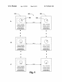
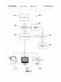
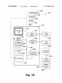
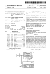
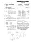
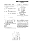
US007925611B1
(12) United States Patent
Bromley et a].
(54)
(75)
GRAPHICAL USER INTERFACE
Inventors: Clifton Harold Bromley, New
Westminster (CA); Monte Leroy
Fevang, Surrey (CA); Sha?n A. Virji,
Vancouver (CA)
(73) Assignee: Rockwell Automation Technologies,
Inc., May?eld Heights, OH (US)
Notice:
Subject to any disclaimer, the term of this
patent is extended or adjusted under 35
U.S.C. 154(b) by 899 days.
2002/0070957 A1
6/2002 Trajkovic et al.
4/2003
2003/0107588 A1*
6/2003
Elsbree et al. .
2003/0120714 A1*
6/2003
Wolff et a1. ................. .. 709/200
2003/0174169 A1
2004/0056890 A1
9/2003 TiWari
3/2004 Hoa et al.
2004/0133853 A1*
(51)
(52)
(58)
706/45, 11; 700/17, 83
See application ?le for complete search history.
OTHER PUBLICATIONS
Jeong-Dan Choi, Ki-Jong Byun, Byung-Tae Jang, Chi-Jeong Hwang
“A Synchronization Method for Real Time Surround Display Using
Clustered Systems”, Dec. 1-6, 2002, 4 pages.
Gordon Stoll, Matthew Eldridge, Dan Patterson, Art Webb, Steven
Primary Examiner * Michael B. Holmes
Assistant Examiner * Adrian L Kennedy
(74) Attorney, Agent, or Firm * Turocy & Watson LLP;
Alexander R. KuszeWski; John M. Miller
(57)
References Cited
U.S. PATENT DOCUMENTS
5,610,839 A *
3/1997
5,801,691 A
9/1998 Dahl
6,199,136 B1*
6,282,454 B1*
3/2001
8/2001
Shteyn ........................ .. 710/305
Papadopoulos et al. ...... .. 700/83
6,411,292 B1*
7,013,297 B2 *
6/2002
3/2006
Cook et al. ............ ..
Miksovsky .... ..
7,017,116 B2*
Karolak et al. ............. .. 455/450
3/2006 Elsbree et al.
.. 345/419
706/60
.. 715/740
2002/0046221 A1*
4/2002
2002/0055984 A1*
5/2002 Chang et a1. ................ .. 709/217
Wallace et al.
..
ABSTRACT
The present invention relates to systems and methods that
facilitates rendering of data in an industrial automation envi
ronment. According to an aspect of the invention, a device
analyzer can determine properties associated With a plurality
of devices intended for delivery of data. An HMI generator
can format the data respectively in accordance With the deter
mined properties of the devices and deliver the formatted data
to the respective devices.
.... .. 707/513
100
20 Claims, 11 Drawing Sheets
x
INPUT
[- 1 10
120
?
715/514
Leonik ........................ .. 709/224
* cited by examiner
(2006.01)
(2006.01)
US. Cl. ............................. .. 706/60; 706/45; 706/11
Field of Classi?cation Search .................. .. 706/60,
(56)
7/2004 Poerner et al. .
10/2004
345/700
Thomas A. Funkhouser and Carlo H. Sequin, “Adaptive Display
Algorithm for Interactive Frame Rates During Visualization of Com
plex Virtual Environments”, 1993, 8 pages.
Sep. 25, 2003
Int. Cl.
G06F 17/00
G06F 17/40
Wong et al. ................. .. 712/220
Berman, Richard Levy, Chris Cay Wood, Milton Taveira, Stephen
Hunt and Pat Hanrahan,“Lightning-2: A High-Performance Display
Subsystem for PC Clusters”, Aug. 2001, 8 pages.
(21) App1.No.: 10/670,582
(22) Filed:
Apr. 12, 2011
2003/0070061 A1*
2004/0205185 A1 *
(*)
US 7,925,611 B1
(10) Patent N0.:
(45) Date of Patent:
[ — — — - _ — — - — — "' " 1
\ll
:
| DEVICE ANALYZER |
l
:
___________ _ _
DATAFORMAT
f
/— 1 30
‘
DEVICE1
DATAFORMAT
2
HMI GENERATOR
14o
_
/
DEVICE2
O
O
DATAFORMATN
DEVICEN
/
150
US. Patent
Apr. 12, 2011
Sheet 1 0111
US 7,925,611 B1
DATAFORMAT
130
100 1‘
INPUT
r110
120 €
__________ _ _
\1r
1'
} DEVICE ANALYZER:
i
1
<——-—1———-—> DEVICE, /
DATAFORMAT
___________ _ _
14o
2
,_
HMI GENERATOR
DEVICEZ
.
.
DATA
Fig. l
15o
FORWN
DEVICEN
/
US. Patent
Apr. 12, 2011
Sheet 2 0111
US 7,925,611 B1
200 W
DATA
220
230
i
___________ _ _
I
/—
210
\
} DEVICE ANALYZER 1
L __________ _ _}
HMI GENERATOR
DATAFORMAT PW
¢
H
HANDHELD PC
(POCKET
WINDOWS)
DESKTOP PC
(WINDOWS NT)
Fig. 2
US. Patent
Apr. 12, 2011
31 0 1
Sheet 3 0111
US 7,925,611 B1
DATA SENT FROM
PHYSICAL DEVICE
320 —\ DATA ggg‘llb/EAgEBY HMI
330 ——\
DATA PROCESSED
350
S-DIMENSIONAL
RENIEQING
—\
Z-DIMENSIONAL
RENDERING
US. Patent
Apr. 12, 2011
41
o\
Sheet 4 0111
US 7,925,611 B1
DATA SENT FROM
PHYSICAL DEVICE
l
420 x DATA RECEIVED BY HMI
SOFTWARE
DATA PROCESSED
440
x
450
‘
DATA VALUE HALVED
460
X
480
\
(VOLUME/AREA HALVED)
DATA VALUE DOUBLED
(VOLUME/AREA DOUBLED)
2
465
Y
3 2X3
470
Fig. 4
—/ 2 2X2
490
US. Patent
Apr. 12, 2011
Sheet 5 0111
500
—\
/"— 520
US 7,925,611 B1
530
_\
540 “
A
h
+
VALUE _ 150 UNITS
VALUE - 15o UNITS
SOFTWARE OBJECT
PHYSICAL DEvIcE
CHANGE MADE TO
CHANGE MADE TO
SOFTWARE OBJECTA
PHYSICAL DEVICEA
.
0
.
0
.
0
___________________________
c
DATA
4
DATA
p
VALUE - 40o UNITS
VALUE ' 15° UN'TS
soFrwARE OBJECT
PHYSICAL DEVICE
CHANGE MADE TO
CHANGE MADE TO
SOFTWARE OBJECTL
PHYSICAL DEVICE,
Q
Q
0
0
0
0
___________________________ “J;
<
DATA
>
VALUE _ 400 UNITS
VALUE - 400 UNITS
SOFTWARE OBJECT
PHYSICAL DEVICE
CHANGE MADE TO
CHANGE MADE TO
SOFFWARE OBJECTA
PHYSICAL DEVICEA
Fig. 5
US. Patent
Apr. 12, 2011
Sheet 6 0111
610
US 7,925,611 B1
f- 600
‘\
DATA ENTERED
/_ 640
620
FORMAT OF
DATA KNOWN’?
ARTIFICIAL
INTELUGENCE
630
650
—\ DATA PROCESSED
660
ERROR MESSAGE
SENT
VI EO
670
680
Fig. 6
AU I0
690
/
US. Patent
Apr. 12, 2011
Sheet 7 0111
US 7,925,611 B1
700 x
71 0
-\
DATA ENTERED
720
\ DEFAULT ZOOM LEVEL
ZOOM LEVEL
CHOSEN’?
DATA RENDEREDA
74o —/
DATA RENDEREDa
750 J
Fig. 7
DATA RENDEREDN
760 J
US. Patent
Apr. 12, 2011
Sheet 8 0111
US 7,925,611 B1
800 x
840
_\\i
850
I
x :
_
SOFTWARE
::
OBJECT
GENERATOR
I
_
_
_
_
_
_
_
w
_
_
_
HMI GENERATOR
821 ——/
HMI GENERATOR
Fig. 8
__
I
US. Patent
Apr. 12, 2011
Sheet 9 0111
900
91 0
x
DATA ENTERED
920
X DETERMINE DATA TYPE
930 x
DETERMINE DATA STATE
940
_\ DETERMINE USER LEVEL
950
x
DATA RENDERED
Fig. 9
US 7,925,611 B1
US. Patent
Apr. 12, 2011
Sheet 10 0f 11
US 7,925,611 B1
‘
___________________________ __
|I
Operating System g
------------------------------------ --
|
:
1010
f
/-- 1030
Applications
——————————— ——:
1l
1028
1032
“webs
_______
1034
'
Data 5
|
........... --
/_
1012
Output
Device(s)
‘\ 1040
Interface :|<_
Vola?le
Port(s)
1020
___,
hput
Dev1ce(s)
Non Volalile
\ 1036
1022 \ 1018
__ g
\_ 1026
f 1050
Communication
Network
Interface
Connection(s)
k
k 1048
Disk Storage
‘
Remote
Computer(s)
1024‘
1044 —/
1046 j
Fig. 10
US. Patent
Apr. 12, 2011
Sheet 11 0f 11
US 7,925,611 B1
/ 1100
11301
SERVER(S)
CLIENT(S)
CLIENT
DATA
STORE(S)
COMMUNICATION
FRAMEWORK
Fig. 11
US 7,925,611 B1
1
2
GRAPHICAL USER INTERFACE
control scheme Within an industrial setting. Disparate plat
TECHNICAL FIELD
With requirements for portability dictated by machine or fac
tory layout. Programming costs increase With a number of
The present invention relates generally to industrial control
systems, and more particularly to the communication and
display of data in a graphical format that can facilitate the
platforms required, as dissimilar platforms require speci?c
control and graphical representation of equipment obtained
objects on a desktop monitor). Furthermore, a HMI created
by a computer programmer can be inef?cient When imple
mented Within an industrial environment, resulting in
increased cost due to system and/or process latency. In such
instances, the programmers Who created the HMI must be
located to re-program such HMI into several disparate plat
forms are required in instances Where control schemes vary
code (e.g., code facilitating display of graphical objects on a
PDA differs from code facilitating display of graphical
from a plurality of devices.
BACKGROUND OF THE INVENTION
Industrial control systems have enabled modern factories
to become partially or completely automated in many circum
forms, thereby compounding de?ciencies of conventional
stances. These systems generally include a plurality of Input
HMIs (e.g., substantially similar HMIs on a PDA and com
and Output (I/O) modules that interface at a device level to
puter monitor, respectively, require separate re-program
sWitches, contactors, relays and solenoids along With analog
ming). In vieW of the foregoing, a system and/ or methodology
control to provide more complex functions such as Propor
mitigating programming costs associated With substantially
tional, Integral and Derivative (PID) control. Communica
tions have also been integrated Within the systems, Whereby
similar HMI(s) displayed on a variety of platforms is desir
20
able.
many industrial controllers can communicate via netWork
SUMMARY OF THE INVENTION
technologies such as Ethernet, ControlNet, DeviceNet,
FOUNDATION Fieldbus, PROFIBUS or other netWork pro
tocols and also communicate to higher level computing sys
tems. Generally, industrial controllers utiliZe the aforemen
The folloWing presents a simpli?ed summary of the inven
25
tion in order to provide a basic understanding of some aspects
of the invention. This summary is not an extensive overvieW
of the invention. It is intended to neither identify key or
critical elements of the invention nor delineate the scope of
the invention. Its sole purpose is to present some concepts of
30
the invention in a simpli?ed form as a prelude to the more
tioned technologies along With other technology to control,
cooperate and communicate across multiple and diverse
applications.
Imperative to factory automation are human-machine
interfaces (HMIs), Which facilitate safe and ef?cient interac
tion betWeen humans and machinery, Wherein manipulation
detailed description that is presented later.
The present invention facilitates rendering of similar HMIs
for a plurality of disparate platforms (e. g., computer monitor,
and control of complex and/or expensive machinery occurs
via a computer. For example, in an industrial setting, a press
operator can utiliZe a HMI to start and/ or stop such press via
depressing a key on a keyboard. Typically, HMIs operable on
PDA, palm pilot, cell phone, . . . ) via automatically generat
35
a computer include a graphical user interface (GUI) to facili
tate display of virtual softWare objects that represent indus
trial system components and/ or actions. For example, a GUI
can alloW display of a factory ?oor on a single display device,
thereby enabling a user to quickly access a component on the
ing code and/ or data that is compatible With the plurality of
platforms. For example, input from a physical device can be
utiliZed to automatically render a substantially similar display
(HMIs) on a plurality of disparate platforms (e.g., an HMI
rendered on a stand alone PC Will be presented in a highly rich
40
format, While an HMI presented on a PDA With limited screen
real estate and processing capability is displayed in a different
format). Input required to render an HMI on a plurality of
factory ?oor via a graphical representation of such compo
nent. The graphical representations in turn have controls
embedded, thus alloWing a user to make real World changes
disparate display devices can be from one or more process
through a visual representation.
points Within an industrial system. For example, a system can
Controls can be implemented to communicate with U0 of
a physical device (eg a pump) via a server. Such an imple
is monitored and data obtained can be utiliZed to render an
include various components, Wherein I/Os of the components
mentation is typically con?gured to alloW a HMI to graphi
HMI. The present invention thus provides for numerous func
tionalities such as truncating various aspects of a rendered
cally display process points (I/O of physical devices) desir
interface so as to make most ef?cient use of capabilities of a
ably controlled by a user. To control one or more process
points, the user can select a graphical softWare object repre
senting the one or more process points. Such exemplary con
trol scheme utiliZes a standard protocol to bring process
points into an HMI environment and to communicate a value
of each process point to an HMI.
50
An HMI also alloWs a user to log data taken on a periodic
55
dered utiliZing the available hardWare device.
basis (e.g. trended data) to determine quality of process points
relating to product manufacturing. For example, trending data
can be desirable to facilitate ef?cient factory maintenance,
quality control, and other similar operations. Furthermore,
such trended data can be used to compare knoWn ideal data
With current data to ensure that a current system is operating
One aspect of the invention relates to a vieW anyWhere
softWare that provides for a highly scalable HMI architecture.
The vieW anyWhere softWare enables graphical display of an
entire factory ?oor, Wherein an operator can navigate through
factory hierarchy until a desirable level is reached. For
example, a factory ?oor can include a plurality of selectable
disparate systems, and the disparate systems can be associ
ated With several components. A user can therefore vieW the
60
factory ?oor and select a desirable system, thereby facilitat
ing display of the system. Thereafter, a speci?c component
properly. Therefore, a production automation system can
“learn” from past data trends and utiliZe trended data to facili
Within the system can be desirably selected, and a graphical
representation of the component, as Well as information relat
ing to the component, can be relayed to a display device. This
tate more ef?cient production.
Conventional HMI systems are associated With high imple
mentation costs, as several platforms (e.g. devices and oper
ating systems) are required by HMI(s) in accordance With a
hardWare device. For instance, an optimal HMI can be ren
65
aspect of the present invention thereby provides for rendering
of HMI in a manner coincident With capabilities of hardWare
employed With the rendering of data.
US 7,925,611 B1
4
3
FIG. 7 is a ?ow diagram for relaying data to a display in
In accordance with one aspect of the present invention,
software objects within a HMI that represent physical devices
can be manipulated, thereby effectuating a desirable response
relation to a Zoom level in accordance with an aspect of the
present invention.
FIG. 8 is a block diagram illustrating automatically gener
ating software objects in accordance with an aspect of the
present invention.
from the physical devices. Software objects representing
physical devices can be rendered in suf?cient detail to display
various intricacies associated with the physical devices. For
example, a physical device can include a variety of mecha
FIG. 9 illustrates a methodology for rendering data based
on a plurality of factors in accordance with an aspect of the
nisms to manipulate operation, including push buttons, slid
present invention.
FIG. 10 is a block diagram illustrating an example operat
ing environment in which the present invention may function.
ers, dials, gauges, etc. A software object representing the
physical device can likewise include graphical representa
tions of such mechanisms, wherein manipulation of the
FIG. 11 is a schematic block diagram of a sample-comput
ing environment with which the present invention can inter
mechanisms in software can effectuate manipulation of the
physical mechanisms.
act.
In accordance with another aspect of the present invention,
data can be delivered to a particular platform in optimal
DETAILED DESCRIPTION OF THE INVENTION
format (e.g., text, images, audio, . . . ). For example, intricate
data can be optimally viewed as an image on a computer
The present invention is now described with reference to
monitor, while the same data is best viewed textually on a
the drawings, wherein like reference numerals are used to
PDA. Determination of a best format for conveying data can 20 refer to like elements throughout. In the following descrip
be facilitated by utiliZing arti?cial intelligence techniques
tion, for purposes of explanation, numerous speci?c details
and/or via user selection. The invention can also employ
AI-based functionality for inferring a best manner in which to
render data given various state conditions and/ or other extrin
sic data and/or historical data and/or training of a classi?er
the present invention. It may be evident, however, that the
present invention may be practiced without these speci?c
details. In other instances, well-known structures and devices
are set forth in order to provide a thorough understanding of
25
are shown in block diagram form in order to facilitate describ
(explicit and implicit) to perform an inference. Furthermore,
if a data type is initially unknown or data partially damaged,
ing the present invention.
known and/ or undamaged data can still be rendered.
As used in this application, the term “computer compo
nent” is intended to refer to a computer-related entity, either
The invention has other aspects such as for example, rich
tag monitors, the ability to drill down within a rendered image
30
presenting the same data in both 2D and 3D, providing for a
a processor, a processor, an object, an executable, a thread of
change in 2D which updates the 3D counterpart in real-time
and vice versa.
To the accomplishment of the foregoing and related ends,
the invention then, comprises the features hereinafter fully
described and particularly pointed out in the claims. The
following description and the annexed drawings set forth in
detail certain illustrative aspects of the invention. These
aspects are indicative, however, of but a few of the various
ways in which the principles of the invention may be
employed and the present invention is intended to include all
35
40
45
environment, and/or user from a set of observations as cap
be probabilisticithat is, the computation of a probability
BRIEF DESCRIPTION OF THE DRAWINGS
50
FIG. 1 is a block diagram illustrating an ability of an HMI
distribution over states of interest based on a consideration of
data and events. Inference can also refer to techniques
employed for composing higher-level events from a set of
events and/ or data. Such inference results in the construction
55
of new events or actions from a set of observed events and/or
stored event data, whether or not the events are correlated in
close temporal proximity, and whether the events and data
come from one or several event and data sources. Various
classi?cation schemes and/or systems (e.g., support vector
machines, neural networks, expert systems, Bayesian belief
60
networks, fuZZy logic, data fusion engines . . . ) can be
employed in connection with performing automatic and/or
inferred action in connection with the subject invention.
tions to a data set in accordance with an aspect of the present
invention.
FIG. 5 is a block diagram illustrating an exemplary system
The present invention relates to a human machine interface
employed to manipulate software objects in accordance with
an aspect of the present invention.
FIG. 6 is a block diagram illustrating output of data to a
display in accordance with an aspect of the present invention.
The subject invention can incorporate various inference
schemes and/or techniques in connection with effecting a
user interface for object management and manipulation. As
used herein, the term “inference” refers generally to the pro
cess of reasoning about or inferring states of the system,
tured via events and/or data. Inference can be employed to
identify a speci?c context or action, or can generate a prob
ability distribution over states, for example. The inference can
sidered in conjunction with the drawings.
platform to output data to a plurality of devices and display
substantially similar characteristics of such data in accor
dance with an aspect of the present invention.
FIG. 2 is an exemplary platform of running an HMI in
accordance with an aspect of the present invention.
FIG. 3 is a ?ow diagram illustrating a methodology for
adjusting graphics in accordance with an aspect of the present
invention.
FIG. 4 is a block diagram illustrating exemplary modi?ca
execution, a program, and/ or a computer. By way of illustra
tion, both an application running on a server and the server
can be a computer component. One or more computer com
ponents may reside within a process and/ or thread of execu
tion and a component may be localiZed on one computer
and/or distributed between two or more computers.
such aspects and their equivalents. Other objects, advantages
and novel features of the invention will become apparent from
the following detailed description of the invention when con
hardware, a combination of hardware and software, software,
or software in execution. For example, a computer compo
nent may be, but is not limited to being, a process running on
(e.g., like map quest) to focus on speci?c target objects,
(HMI) that facilitates rendering data in a platform (eg an
65
operating system within a network) to display substantially
similar data in disparate platform(s). The HMI can utiliZe a
plurality of factors, such as disparate platforms running
US 7,925,611 B1
5
6
HMls, display component size and/or resolution of a device
receiving data, etc., to generate proper data format for a
display device Within an industrial setting. In addition, plug
and-play technologies can be utiliZed in connection With the
present invention to facilitate automatic generation of prop
erly formatted data in accordance With a particular electronic
synchronous RAM (SRAM), dynamic RAM (DRAM), syn
chronous DRAM (SDRAM), double data rate SDRAM
(DDR SDRAM), enhanced SDRAM (ESDRAM), Synchlink
DRAM (SLDRAM), and direct Rambus RAM (DRRAM).
The memory and the processor associated With the device
analyZer 120 can be employed to store information regarding
devices 130-150 to Which data is delivered. Accordingly,
devices 130-150 can be recogniZed and formatting require
device (e.g., display device, storage device, relay
device, . . . ). Based on knoWn attributes of a platform and its
capabilities, an HMI can be modi?ed to accommodate a neW
ments can be knoWn upon an occurrence that the devices
setting in Which data and/or code Will be delivered. It is to be
appreciated that any discussion herein pertaining to “data” or
and processor alloW the device analyZer 110 to accumulate
130-150 are interfaced to a netWork. Therefore, the memory
and utiliZe data formatting requirements of the devices 130
150 employed in subsequent data transfers.
Arti?cial intelligence (Al) techniques can be utiliZed to
determine formatting, thereby enabling data delivered to the
devices 130-150 to be properly formatted. For example, the
devices 130-150 can be disparate display devices (e.g., a
“code” or “data and/ or code” is intended to encompass either
“data” or “code,” or both “data” and “code.” Likewise, Where
the Word “code” is used, “data” is also implied.
The present invention enables proper formatting of HMI
data to be distributed throughout a netWork comprising a
plurality of devices, Wherein the devices require speci?c for
matting to properly render the HMI data. Further, designing
desktop monitor, hand-held monitor, PDA, . . . ), and graphi
and creating in a single location provides for the HMI inter
face to be standard. For example, a template for the HMI can
be stored on a central computer and utiliZed throughout the
20
techniques can be associated With a memory device in order
to automatically facilitate data formatting requirements nec
entire netWork. Thus, it should be appreciated that this aspect
of the present invention reduces HMI control design and
essary for the transfer of data to a speci?c device. For
development.
Referring noW to FIG. 1, a system 100 facilitating auto
25
ate platforms is illustrated. The system 100 comprises an
HMI generator 110 that can accept data from physical devices
and deliver data (e.g., a HMI) to a plurality of disparate
30
tions of physical devices, Wherein manipulation of the soft
Ware representations effectuates change of state in the physi
cal devices. The devices 130-150 can be any device utiliZed
for storing, displaying, and/ or relaying data. For example, the
device 130 can be a display, the device 140 can be a data store,
and the device 150 can be a server. Furthermore, the devices
35
can be disparate display devices, such as a desktop computer
monitor, a PDA, cell phone display, industrial PC, hand-held
PC, etc. The physical devices relaying data to the HMI gen
erator 110 can include various components in an industrial
40
network. Typically, data paths to process points are stored
When a softWare representation of the physical device is origi
nally created in the HMI generator 110. HoWever, When the
HMI generator 110 is employed to relay properly formatted
HMI data to the devices 130-150, and the properly formatted
data is delivered to the display devices 130-150 located else
Where in the netWork, there is inherently a different path to the
process point(s) at the physical device. For example, if the
properly formatted data is located at the HMI generator 1 10 in
location Fz/Comp4/OPCServer/PLC5/00l/GRl50, the path
to the process point location can vary after the data is trans
ferred to the device 130 located at Fz/PDAl/PocketOPC
Server/PLC5/00l/GR150. The mapping can facilitate
changes in a data path to mitigate loss of data connectivity,
thereby enabling proper communication betWeen the data and
ibility requirements of the devices 130-150. For example,
the HMI.
Referring noW to FIG. 2, an exemplary system 200 facili
50
tating automatically generating and relaying properly format
55
ted data to a particular operating system is illustrated. An
HMI generator (desktop PC) 210 is utiliZed on a WindoWs NT
platform and is representative of a location to design and
create HMls. A device analyZer 220 is utiliZed to format and
deliver data to a display device (handheld PC) 230 in accor
analyZer 120 can make appropriate format changes to the data
to accommodate the difference in resolutions. The HMI gen
erator 110 can relay a variety of data formats to one or more
devices 130-150, Wherein the data delivered to the devices
130-150 is compatible With such devices 130-150. For
example, device 130 can require tWo or more disparate for
mats to enable optimal HMI rendering.
Further, the device analyZer 120 can map data path infor
mation to data delivered to the device(s) 130-150. The data is
representative of one or more process points from a physical
device input into the HMI generator 110 located Within a
one location and data representing a process point has a
environment, such as valves, pumps, relays, presses, etc.
The system 100 further comprises a device analyZer 120
that facilitates determining properties of the devices 130-150
to Which data Will be delivered via the HMI generator 110.
Formatting and delivering the data to the devices 130-150 can
occur automatically in accordance With particular compat
data delivered from physical device(s) can be formatted for a
particular screen resolution While device 130 can be a display
device utiliZing a disparate screen resolution. The device
example, if the device 130 has already been connected to and
received data from the HMI generator 110, data formatting
can be done automatically upon a subsequent occurrence that
the device 130 is connected to the HMI generator 110.
matic generation of tWo or more HMls on at least tWo dispar
devices 130-150. The HMI can include softWare representa
cal representations desirably displayed can appear substan
tially similar on each display device. Furthermore, the Al
dance With requirements of the display device 230 receiving
the data from the HMI generator 210. In accordance With one
aspect of the present invention, the data is delivered from a
desktop PC 210 employing a WindoWs NT platform to a
The device analyZer 120 can be associated With a memory
(not shoWn) and a processor (not shoWn). The memory of the
device analyZer can be, for example, volatile memory and/or
handheld PC 230 employing a Pocket WindoWs operating
nonvolatile memory. For example, nonvolatile memory can
system.
include read only memory (ROM), programmable ROM
The device analyZer 220 can be employed to format data
delivered from the HMI generator 210 to the display device
(PROM), electrically programmable ROM (EPROM), elec
230. Utilizing the device analyZer 220, formatting require
trically erasable ROM (EEPROM), and/or ?ash memory.
Volatile memory can include random access memory (RAM),
Which acts as external cache memory. By Way of illustration
and not limitation, RAM is available in many forms such as
65
ments for the display device 230 Will be determined once the
handheld PC 230 is coupled With the system 200 by contem
plating a plurality of factors such as memory capacity, video
US 7,925,611 B1
7
8
capabilities, screen resolution and screen siZe of the device.
After determining the formatting requirements for the hand
Differences betWeen the desktop PC 210 and the handheld
PC 230 can necessitate different data formatting require
held PC 230, data Will be transferred from the desktop PC 210
With proper data format, thereby enabling the data on the
handheld PC 230 to be displayed properly.
memory and processor speeds. The present invention advan
tageously solves the problem created by differences in com
The handheld PC 230 can include several limitations
puter processing speed and display requirements by format
ments based on screen resolutions, color capabilities,
requiring data formatting to be modi?ed from the original
ting data required by the handheld PC 230. For example, a
state of the HMI generator 210 employed With a desktop PC.
3-dimensional softWare object created on a desktop PC 210
For example, a plurality of operating systems can be run on a
plurality of handheld PCs. A handheld PC can run Pocket
With a CRT monitor may be converted to a 2-dimensional
object When data is delivered to a handheld PC 230 With a
WindoWs, Palm OS or Linux OS platforms, Wherein the plat
forms can have disparate formatting requirements for the data
as it is input into the handheld PC. Furthermore, Microsoft
an HMI based on an assumption that the HMI Will run on a
small LCD monitor. To further this example, a user can design
particular device, such as a desktop PC With a CRT display.
Pocket WindoWs can run on a plurality of processor types
While the HMI runs on the desktop PC, it may not run cor
such as MIPS, SH3 and ARM.
Another consideration is the amount of memory available
to process the data from the HMI generator 210 on a handheld
PC 230. The memory available in a desktop computer is
de?ned in terms of hard drive space and RAM. A typical hard
drive in a desktop PC can contain 50 gigabytes of storage and
rectly on a device With limited memory, display capability,
etc., such as the handheld PC described above. The HMI
generator 210 can recogniZe the limitations of the less
capable device and morph the HMI application to run in a
manner suitable to the limitations of the smaller and/or less
20
provide for 512 megabytes of RAM memory. In comparison,
Referring noW to FIG. 3, a method 300 illustrates process
ing and rendering data in both tWo and three-dimensional
renderings at substantially the same time. Initially, data is sent
a handheld PC can be restricted to 32 megabytes of storage
space and 64 megabytes of RAM. Memory limitations can
limit the amount of HMI data stored on a device and also limit
the amount of data that can be processed When running an
capable device.
25
HMI application. Furthermore, the processing capabilities on
from a physical device 310 Which is received by an HMI 320.
Algorithms associated With the HMI are employed to process
the data 330 into a tWo-dimensional 340 and/ or three-dimen
sional 350 softWare object based on a user selection. TWo
a handheld PC 230 Will be much loWer than that of a desktop
PC 210. For example, the processing speed of a typical desk
dimensional rendering enables data to be displayed utiliZing
top PC utiliZes a 2-gigahertZ processor compared to a hand
a tWo-axis methodology. The rendering of the data is corre
lated to process point values and alloWs for variance of a
tWo-dimensional object in a plurality of attributes such as
held PC’s 400-megahertz processor.
Also, consideration of screen siZe, resolution and color
capabilities of a handheld PC 230 compared to a desktop PC
210 is necessary to determine data formatting requirements.
For example, a desktop PC 210 can have a screen siZe of 17
inches Where a handheld PC 230 may have a screen siZe of 3.8
30
size, color variance, etc. Furthermore, the data set utilized to
35
inches providing for siZe of all components displayed on a
smaller scale in the handheld PC 230. Further, the screen
resolution and color capability of the handheld PC 230 is
more restrictive than the desktop PC 210. For example, a
standard screen resolution of a monitor utiliZed With the desk
40
top PC 210 can be 1024 by 768 pixels. By comparison, screen
resolution of the handheld PC 230 can be 240 by 320 pixels.
45
Furthermore, colors available in a handheld PC 230 may
not alloW for similar display of data as created on a desktop
PC 210 unless the data is formatted properly. For example, the
display on a handheld PC 230 may be capable of recognizing
50
64-bit depth and 16 million colors in a desktop PC 210.
Therefore, data transferred from the desktop PC 210 can
provide for a loWer color bandWidth to deliver graphics to the
typical desktop PC 210 utiliZes a CRT monitor Which is
brighter and has better screen resolution than a comparable
LCD display found on a handheld PC 230. Furthermore, the
vieWing angle of an LCD display is loWer than a CRT display.
For example, an LCD display can alloW for 100 degrees of
vieWing angle Where a CRT monitor can provide for almost
180 degrees of vieWing angle from the front of the monitor.
re?ected at substantially the same time in both a 2-dimen
sional HMI softWare object 450 and a 3-dimensional HMI
55
a 3-dimensional HMI object. For example a 2-D rectangle can
be associated to a process point (e.g. I/O from a physical
device) in a plurality of Ways. A change in the data value can
be displayed as a change in only the height of the rectangle or
alternatively can be shoWn as a change to both the height and
60
Width of the rectangle. Similarly, a 3-dimensional rectangle
can associate process points that adjust the height, Width or
length individually or all three dimensions at substantially the
handheld PC 230.
Another consideration is the type of monitor utiliZed to
display the softWare objects employed With the HMI. TWo
types of technologies relating to computer monitors include
CRT (cathode ray tube) and LCD (liquid crystal display). A
liZed to modify aspects of softWare objects in 2-dimensions
describing the same process points as softWare objects dis
played in 3-dimensions. Data is sent from a physical device
410 and received by an HMI generator 420. The data is
processed 430 and changes in the value of data Will be
softWare object 440 re?ecting a corresponding change in
value of the process point.
Changes in the data values can be displayed differently in
a 2-dimensional HMI softWare object than the data change in
and displaying 16-bit depth and 64,000 colors compared to
handheld PC 230 facilitating proper display of data by the
data and provide data sets displaying values corresponding to
values of process points associated With physical devices. The
algorithm is utiliZed to process the data sent and provide data
sets displaying values corresponding to values of process
points associated With physical devices. A user may choose
the appropriate algorithm or algorithms to properly render a
softWare object to an HMI.
Turning noW to FIG. 4, a methodology 400 is shoWn uti
Accordingly, a different data format is required to accommo
date the loWer resolution to enable displaying graphics in a
substantially similar manner regardless of the platform on
Which the HMI is displayed.
display a three-dimensional softWare object can be associated
With process point values in the same manner.
The HMI contains an algorithm or algorithms to process
same time.
The user may select speci?c changes made to softWare
65
objects associated With process point value changes. For
example, the area of a 2-dimensional square can be associated
so that it Will double in area When the value of a corresponding
US 7,925,611 B1
10
process point doubles in value. Similarly, the volume of a
Square:
3-dimensional cube can be assigned so that it Will double in
Area4each side can be X,
volume When the value of a corresponding process point
doubles in value.
If Y is doubled, each side can be expressed as:
YIX2
If Y is halved, each side can be expressed as: (1/2*X2
For example, a process point can be associated to the
square by a user so a linear relationship exists betWeen the
In a softWare object that is a 3-dimensional square, Z
denotes an initial value of a process point and initial volume
associated With the square. The value of each side of the cube
can be expressed as an equation:
value of the process point and the area of the square. There
fore, if the initial area of a square is 1 unit2, When the value of
the process point value doubles, the process point associated
With the area of the square Will be 2 unit2 and the length and
Width Will 1.41421 units. Comparatively, the volume of a
Cube:
Volumeieach side can be X,
cube can be associated With a process point so that a linear
If Z is doubled, each side can be expressed as: \3/
relationship exists betWeen the value of the process point and
If Z is halved, each side can be expressed as: \3/\/(1/2)X3
the volume of the cube. Therefore, a cube With an initial value
of 1 unit3 can double When the process point value doubles
creating a software object Where the volume of the cube Will
be 2 unit3 and the length, Width and height Will be 1.25599
units.
The difference in the relationship of a process point asso
Referring noW to FIG. 5, illustrating an exemplary system
employed to manipulate softWare objects capable of chang
ing data values of process points associated With physical
devices by changing data values associated With softWare
objects representing physical devices. A user can utiliZe an
20
ciated With a square and a cube can be demonstrated by using
another example extrapolating the values so the process point
value increases by 16 times. The folloWing equations dem
onstrate the difference required in 2 and 3 dimensional
objects necessary to vary the siZe of the softWare object.
point. The modi?cation to the control can come from a plu
25
SquareiWidthxheight
30
methods such as an physical object representation imported
as a .bmp, .jpg or .dxf ?le or the like to utiliZe pre-fabricated
Original valueil unit3:1 unit><1 unit><1 unit
Process point doublesi2 unit3:1.2599 units><1.2599
art in the HMI. Also, an object can be selected from a plurality
of objects contained in a library Within the HMI or simply
units><1.2599 units
created by the user using draWing tools and saving the object
There is a difference of 0.15431 or 7.7% of each corre
35
SquareiWidthxheight
Original valueil unit2:1 unit><1 unit
Process point (><16)i16 unit2:4 units><4 units
Cubeiwidthxheightxlength
dials, and gauges. Controlling a physical device utiliZing a
softWare object representing the device, requires a process
point associated With the physical device to be connected to
the softWare object via an HMI.
The softWare object can be created using a plurality of
units
sponding side to double the value betWeen the 2-D area and
3-D volume.
appropriate control associated With the softWare object and
adjust the control to affect the change to the desired process
rality of softWare objects including sliders, push buttons,
Original valueil unit2:1 unit><1 unit
Process point doublesi2 unit2:1.41421 units><1.41421
Cubeiwidthxheightxlength
ZIX3
40
Within the HMI environment.
The softWare object can be connected to the physical
device by Way of selecting a process point from a nested data
structure representing the process points available in the con
trol architecture. The nested data structure can represent the
path to the process point on the factory ?oor from the com
Original valueil unit3:1 unit><1 unit><1 unit
puter Where the HMI generator resides. Further, multiple
Process point (><16)i16 unit3:2.5198 units><2.5198
process points can be selected and associated With a single
softWare object to alloW communication betWeen the soft
Ware object and the process points. The process points can be
utiliZed to modify a plurality of attributes associated With the
units><2.5198 units
There is a difference of 1.4802 or 9.25% of the (x16) value
betWeen the 2-D and 3-D rendering.
It should be appreciated that the value of the volume of the
cube is increased in a greater proportion to the area of square
When the value of a process point doubles. That is to say, in
order to affect a greater change in the volume of a cube
requires a loWer change in the dimension of each side. This
disparity becomes more apparent as the value of the process
45
softWare object including color, siZe, shape and location on
the screen. For example, a tWo-dimensional square softWare
obj ect can have tWo process points associated With it. The ?rst
process point can be utiliZed to vary the area of the square
50
second process point can be used to vary the location of the
point increases.
Also, it should be appreciated that the values relating to an
example of rendering the data in tWo and three dimensions
can be quanti?ed as values derived from geometric equations.
After the data is sent from the physical device 410, received
by the HMI softWare 420 and the data is processed 430 the
corresponding to a change in the ?rst process point value. A
55
softWare object corresponding to a change in the second
process point value.
Once the softWare object is created and process points are
associated With the software object, an object is capable of
outputting values to the physical device and also capable of
accepting input values from the physical device. The system
500 shoWs a softWare object capable of controlling and vary
ing a process point associated With a physical device. The
data can be rendered in substantially the same time as a
2-dimensional 450 and 3-dimensional object 440. In this
initial value, a formula can be utiliZed to express the siZe of
softWare object 520 contained Within the HMI 510 can be
created and associated to a process point associated With a
physical device as described above. Data represents the con
the softWare objects in their proper proportional siZes.
nectivity betWeen the software object and physical device
example, the data is rendered as both a 2-dimensional square
and a 3-dimensional cube. After the data is changed from its
In a softWare object that is a 2-dimensional square, Y
denotes an initial value of a process point and initial area
associated With the square. The value of each side of the
square can be expressed as an equation:
60
65
found on the factory ?oor.
Stage A shoWs a softWare object 510 and an associated
physical device 530 depicting an initial value 150 units of a
physical device process point.
US 7,925,611 B1
11
12
Stage B illustrates a change in the value of the process point
via the software object 520 which can be changed by a user
from 150 units to 400 units. However, the change in value 520
made to the software object has not yet been transferred to the
physical device 540 due to a delay caused by processing. This
delay is inherent in electrical control systems, and can be
composed of a processing time in the software and/or hard
audio, textual, etc. sub-formats and modify the data and/or
code generated to be suitably rendered on the device. In a
similar manner, the present system can determine, for
example, scripting languages (e.g., Java-script,V1sual Basic
for Applications, etc.), plug-ins (e.g., ActiveX controls, Ole
Objects, etc.) etc., associated with and/or supported by a
particular device and modify data and/or code accordingly to
provide a “best ?t” for the device.
If the format of the data type is unknown, arti?cial intelli
gence (A/ I) 640 is employed to determine a proper format in
ware of the device, a data transfer time and a processing time
in the software and/ or hardware of the physical device. There
fore, the changed value of a process point in the HMI genera
tor 510 is unchanged in the physical component 540 and
which to render the data. The A/I can render the data in a
remains at the initial value of 150 units.
Stage C shows the value of the process point in the software
object 520 in the HMI 510 having the value transferred from
the HMI 510 to the physical device 540. The data value is
updated in the physical device 530 and re?ects the change
value of the process point made from the software object 510
to the physical device 530.
Further, it should be appreciated that the data can ?ow in
two directions both from the HMI to the physical device and
from the physical device to the HMI. Therefore, the above
illustration represents only one instance of data transfer. The
data value can also be transferred from the physical device
540 to the software object 520. In this scenario, the value of
the process point would be ?rst changed in the physical
variety of ways until a proper format is identi?ed and then
format and render the data properly. If the A/ I determines that
none of the data introduced can be read 650, the data is not
processed and an error message is sent 660 to the HMI. The
error message may be transmitted in a plurality of formats.
For example, the error message may be transmitted by having
the data value appear as a series of grayed out asterisks on the
20
670-690 within the HMI as described above.
Thus, A/I can be utiliZed to render data in a suitable format
25
device 530. The means to facilitate such change would occur
from a pushbutton, dial indicator, or some other input appa
ratus connected to the physical device. The system would also
provide for an alternative system of data transfer whereby the
data would ?rst be changed in the physical device then later
re?ected in the software object as data that is changed. There
30
Therefore, the memory will allow for a more e?icient method
35
of rendering data properly when an unknown type of data is
introduced.
Referring now to FIG. 7, a methodology 700 illustrates
cluttering or de-cluttering data in a display associated with a
40
plurality of disparate views associated with a display coupled
Zoom level chosen in an HMI. The Zoom level relates to a
with an HMI wherein data associated with process points can
be hidden or exposed to the user. Further, it should be appre
ciated that the Zoom level and the data exposed does not
introduced matches a known data format then the data will be
processed 630 and rendered as at least one of text 670, video
680 or audio 690. (It is to be appreciated that, although ren
dered data is described herein as text, video, and/or audio, the
(not shown) that will allow unknown data types to be stored
type of data format and the known method of rendering the
data allowing the data to be rendered by the HMI properly.
tively.
Referring now to FIG. 6, showing a methodology 600 for
determining data format and rendering data in a proper for
mat. Initially, the data is entered into the HMI 610 and the
format of the data is queried 620. For example, one method of
determining format of the data is to compare the data to
known formats until one is found that is matching. If the data
if data format is unknown. Further, A/I can render a portion of
data if substantially all the data cannot be rendered and allow
the readable data to be sent to the HMI environment. For
example, if data is introduced with partially defective or
unreadable information, data that is undamaged can still be
located and rendered.
Further, the A/I 640 can have associated with it a memory
and utiliZed if they are introduced. The memory will store the
fore the data transfer is shown as a bi-directional ?ow since
either the software object or the physical device can ?rst
provide a change in the process point that will later be
re?ected by the physical device or software object respec
HMI display. However, if the A/I determines that some data
can be read 650, the data will be processed 630 and rendered
necessarily represent a linear relationship whereby the
45
present invention contemplates rendering data in any suitable
format, including but not limited to static images, interactive
images, etc.) For example, text can include written instruction
greater the Zoom level, the greater amount of process point
values are exposed. The process points can be associated with
substantially any level of Zoom and allow the data to be
displayed in whatever fashion the user desires. Arti?cial intel
ligence (not shown) can be utiliZed to infer a default Zoom
such as speci?c pages from a user manual or a written value 50 level based on past Zoom levels chosen by a user.
representing a process point. Similarly, video rendering can
Initially, data is entered into the HMI 710 and rendered
include video instruction to an HMI user or can illustrate a
based on a default Zoom level 720. After a user chooses a
process function that is currently taking place. Audio format
Zoom level 730 data is rendered 740-760 based on the
ting can refer to a sound signifying a certain condition within
assigned Zoom level chosen by the user. This methodology is
the system, or can be an audible instruction to the user to take 55 bene?cial in a display wherein a plurality of process points
action. Additionally, the present invention can employ text
exist that do not require exposure to the user at substantially
to-speech capabilities whereby, for example, values of pro
the same time. Some HMI displays inherently require data to
be exposed as the user “drills down” into each display. For
cess points can be spoken to a user in a language of the user’ s
choice (e.g., “The ?uid temperature in mixing vessel number
three is one hundred eighty degrees Celsius.”).
Furthermore, this aspect of the invention provides for
example, an initial screen in an HMI can show an entire plant
60
?oor which does not necessitate exposing the value of every
process point when viewing an initial screen. However, as the
determining sub-formats of data, which can include, but are
user selects disparate Zoom levels associated with for
not limited to, ANSI, UNICODE, fonts, 3-D text, mp3, .wav,
jpeg, mpeg, etc. For example, a particular device may be
example each speci?c production line and each physical
capable of an audio ?le in .wav format but not in mp3 format.
The present invention can recogniZe a device’s rendering
limitations with respect to, for example, graphical, video,
device associated with the line, the values of each process
65
point can be exposed to the user. The Zoom level and associ
ated data can be assigned in order to facilitate rendering of
data when a certain Zoom level is selected.
US 7,925,611 B1
14
13
objects 811, 821, 831 in an HMI after physical devices 810,
server being utiliZed. Next, the system would poll the network
containing the physical devices and determine what IP
addresses were assigned to each component. For example, if
820, 830 are connected to the HMI. Further, the SOG is
the OPC server were employed to communicate to Ethernet,
associated with arti?cial intelligence (A/I) techniques (not
substantially all IP addresses associated with each physical
device would be determined and compiled in the HMI. After
ward, the IP addresses and location of each device would be
referenced together to determine what device existed at that
address. The software object associated with the device is
Turning now to FIG. 8, a system 800 illustrates software
object generator (SOG) 840 capable of creating software
shown) providing means for recognizing a physical device,
providing for a software object representing the physical
device and providing a software object in an HMI. The soft
ware object provides for substantially similar I/O as the
physical device with the I/O connectivity already in place.
Further, the software object 811, 821, 831 will have substan
tially similar graphical representation relating to the physical
then employed to control the physical device when imple
mented.
Further, the software object created will provide the same
I/O as the physical device. For example, if a device contains
device 810, 820, 830 providing for an intuitive user interface
to the physical device.
The SOG 840 is associated with an HMI generator 850
utiliZed to create interfaces to physical devices 810, 820, 830.
Initially, a physical device 810 can be interfaced to the HMI
generator 850 through a plurality of means including an inter
12 digital inputs, 5 digital outputs, 3 analog outputs and 2
analog inputs, the software object would contain the same
I/O. Also, the proper I/O would be assigned to the proper
face to a control network to facilitate a recognition process.
Interfacing to the HMI generator allows a polling process to
20
register on the PLC or other programmable machine control
device that interfaced to the physical device before the I/O
was networked with the rest of the plant.
Referring now to FIG. 9, representing a methodology 900
initiate wherein the protocol required to communicate with
to determine how data is rendered in an HMI based on a
the device is ?rst utiliZed in order to determine a family of
products a physical device is associated with. The SOG is
enabled to facilitate communication to a database containing
plurality of factors. First, the data is entered 910 into an HMI
through a data server and the data type is determined 920. The
data type refers to the format of the data and whether the data
is best rendered as for example text, audio or visually. For
a plurality of software objects representing the physical
devices. From the polling conducted and results regarding the
communication of the physical device and I/O of the physical
25
example, if the data were in .wav format, a method to render
the data would be in an audio format.
device, a comparison is made to the software objects associ
ated with the database.
Furthermore, the SOG 840 is associated with an AI com
30
ponent (not shown) which facilitates recognizing a new
physical device added to the system. The AI component will
monitor the system on a periodic basis to ensure that substan
tially all the devices connected to the system are represented
and available as a software object. After the AI component
35
recogniZes the newly added physical device 810, the compo
nent is created and added to an HMI library and made avail
able to a user. Also, the HMI will recogniZe substantially all
the components connected to the system so that upon initial
startup for the HMI, the physical devices connected to the
40
Next, the state of the data is determined 930 to help decide
how the data will be rendered. Logically gating I/O from the
data can be accomplished utiliZing a ladder logic interface
(not shown) enabled to control the attributes of software
controls. For example, if the data is higher than a pre-deter
mined set point, the font selected for the data displayed can be
red and boldfaced. However, if the data falls below the pre
determined set point, it can be displayed in a font with blue
color and no boldface. Other attributes to the software objects
can be changed accordingly. Logic parameters can be incor
porated and saved and associated with a software object and
saved in an associated memory (not shown) to utiliZe in the
future.
HMI will be available as software objects and ready for use in
the HMI.
Furthermore, a user level is determined 940 to ?nd what
type of access a user will have to the data. The data can be
By allowing physical devices to be recogniZed by the HMI
made inaccessible in a number of ways to either prevent the
user from making any changes to the process point or to have
and available to the user, the programming of the system
becomes more e?icient. The user is not required to re-create
45
software objects utiliZed from project to project that involve
substantially the same physical devices. The user can simply
may view the data but are unable to make any changes to the
data. Similarly, if the user does not have the proper access
level, some data points can be hidden from the user com
choose the object from a library and implement the object in
the current project as well as future projects that utiliZe the
same or similar physical devices.
Further, the SOG 840 provides for paths to the process
points on the physical devices to the software object that
allows the user to make changes to the process points (I/O)
related to each physical device. The paths associated with
each process point are automatically associated with the soft
ware object and allow for connectivity to the appropriate
50
eters, data is rendered 950 and can be exposed, hidden or
55
drag and drop the software object into an HMI and almost
60
The path to the respective U0 is determined from a data
For example if an OPC server were utiliZed to bring the tags
into the HMI, the ?rst query would relate to the type of OPC
In order to provide a context for the various aspects of the
invention, FIGS. 10 and 11 as well as the following discussion
are intended to provide a brief, general description of a suit
able computing environment in which the various aspects of
the present invention can be implemented. While the inven
tion has been described above in the general context of com
puter-executable instructions of a computer program that runs
on a computer and/or computers, those skilled in the art will
recogniZe that the invention also can be implemented in com
bination with other program modules. Generally, program
modules include routines, programs, components, data struc
server and how the data server receives its information. The
data server is polled and the path to the data is found as a
function of the network protocol employed and the location of
the physical device.
pletely. Therefore, taking into account all the above param
disabled corresponding to such as user access level, data state
or data type.
physical device I/O. In this manner, the user is able to click,
immediately begin to affect changes to the physical device
associated with such object.
the process point completely hidden from the user. For
example, if the user does not have the proper access level they
65
tures, etc. that perform particular tasks and/or implement
particular abstract data types. Moreover, those skilled in the
art will appreciate that the inventive methods may be prac
US 7,925,611 B1
15
16
ticed With other computer system con?gurations, including
single-processor or multiprocessor computer systems, mini
acts as an intermediary betWeen users and the basic computer
computing devices, mainframe computers, as Well as per
resources described in suitable operating environment 1010.
sonal computers, hand-held computing devices, micropro
Such softWare includes an operating system 1028. Operating
ces sor-based or programmable consumer electronics, and the
system 1028, Which can be stored on disk storage 1024, acts
to control and allocate resources of the computer system
It is to be appreciated that FIG. 10 describes softWare that
like. The illustrated aspects of the invention may also be
1012. System applications 1030 take advantage of the man
agement of resources by operating system 1028 through pro
practiced in distributed computing environments Where task
are performed by remote processing devices that are linked
through a communications network. HoWever, some, if not all
aspects of the invention can be practiced on stand-alone com
gram modules 1032 and program data 1034 stored either in
system memory 1016 or on disk storage 1024. It is to be
appreciated that the present invention can be implemented
With various operating systems or combinations of operating
puters. In a distributed computing environment, program
modules may be located in both local and remote memory
systems.
storage devices.
A user enters commands or information into the computer
With reference to FIG. 10, an exemplary environment 1010
for implementing various aspects of the invention includes a
computer 1012. The computer 1012 includes a processing
unit 1014, a system memory 1016, and a system bus 1018.
1012 through input device(s) 1036. Input devices 1036
include, but are not limited to, a pointing device such as a
mouse, trackball, stylus, touch pad, keyboard, microphone,
The system bus 1018 couples system components including,
but not limited to, the system memory 1016 to the processing
unit 1014. The processing unit 1014 can be any of various
20
available processors. Dual microprocessors and other multi
port, a parallel port, a game port, and a universal serial bus
(U SB). Output device(s) 1040 use some of the same type of
processor architectures also can be employed as the process
ing unit 1014.
The system bus 1018 can be any of several types of bus
joystick, game pad, satellite dish, scanner, TV tuner card,
digital camera, digital video camera, Web camera, and the
like. These and other input devices connect to the processing
unit 1014 through the system bus 1018 via interface port(s)
1038. Interface port(s) 1038 include, for example, a serial
25
structure(s) including the memory bus or memory controller,
ports as input device(s) 1036. Thus, for example, a USB port
may be used to provide input to computer 1012, and to output
a peripheral bus or external bus, and/or a local bus using any
information from computer 1012 to an output device 1040.
variety of available bus architectures including, but not lim
ited to, 11-bit bus, Industrial Standard Architecture (ISA),
Micro-Channel Architecture (MSA), Extended ISA (EISA),
Output adapter 1042 is provided to illustrate that there are
some output devices 1040 like monitors, speakers, and print
30
Intelligent Drive Electronics (IDE), VESA Local Bus (VLB),
Peripheral Component Interconnect (PCI), Universal Serial
Bus (U SB), Advanced Graphics Port (AGP), Personal Com
puter Memory Card International Association bus (PCM
CIA), and Small Computer Systems Interface (SCSI).
a means of connection betWeen the output device 1040 and
the system bus 1018. It should be noted that other devices
35
The system memory 1016 includes volatile memory 1020
and nonvolatile memory 1022. The basic input/ output system
(BIOS), containing the basic routines to transfer information
betWeen elements Within the computer 1012, such as during
start-up, is stored in nonvolatile memory 1022. By Way of
40
1044 can be a personal computer, a server, a router, a netWork
45
PC, a Workstation, a microprocessor based appliance, a peer
device or other common netWork node and the like, and
typically includes many or all of the elements described rela
tive to computer 1012. For purposes of brevity, only a
memory storage device 1046 is illustrated With remote com
include read only memory (ROM), programmable ROM
(PROM), electrically programmable ROM (EPROM), elec
puter(s) 1044. Remote computer(s) 1044 is logically con
Which acts as external cache memory. By Way of illustration
and not limitation, RAM is available in many forms such as
synchronous RAM (SRAM), dynamic RAM (DRAM), syn
chronous DRAM (SDRAM), double data rate SDRAM
(DDR SDRAM), enhanced SDRAM (ESDRAM), Synchlink
50
DRAM (SLDRAM), and direct Rambus RAM (DRRAM).
Computer 1012 also includes removable/non-removable,
volatile/non-volatile computer storage media. FIG. 10 illus
trates, for example a disk storage 1024. Disk storage 1024
includes, but is not limited to, devices like a magnetic disk
55
tion, disk storage 1024 can include storage media separately
60
device (CD-ROM), CD recordable drive (CD-R Drive), CD
reWritable drive (CD-RW Drive), digital versatile disk ROM
drive (DVD-ROM), DVD recordable drive (DVD-R), DVD
1024 to the system bus 1018, a removable or non-removable
interface is typically used such as interface 1026.
Ethemet/IEEE 1102.3, Token Ring/IEEE 1102.5 and the like.
WAN technologies include, but are not limited to, point-to
point links, circuit sWitching netWorks like Integrated Ser
vices Digital NetWorks (ISDN) and variations thereon, packet
sWitching netWorks, and Digital Subscriber Lines (DSL).
drive, ?oppy disk drive, tape drive, JaZ drive, Zip drive,
reWritable drive (DVD-RW), and any other suitable DVD
drives. To facilitate connection of the disk storage devices
nected to computer 1012 through a netWork interface 1048
and then physically connected via communication connec
tion 1050. NetWork interface 1048 encompasses communi
cation netWorks such as local-area netWorks (LAN), Wide
area netWorks (WAN), and Wireless Wide-area netWorks
(WWAN). LAN technologies include Fiber Distributed Data
Interface (FDDI), Copper Distributed Data Interface (CDDI),
LS-100 drive, ?ash memory card, or memory stick. In addi
or in combination With other storage media including, but not
limited to, an optical disk drive such as a compact disk ROM
and/or systems of devices provide both input and output capa
bilities such as remote computer(s) 1044.
Computer 1012 can operate in a netWorked environment
using logical connections to one or more remote computers,
such as remote computer(s) 1044. The remote computer(s)
illustration, and not limitation, nonvolatile memory 1022 can
trically erasable ROM (EEPROM), or ?ash memory. Volatile
memory 1020 includes random access memory (RAM),
ers, among other output devices 1040, Which require special
adapters. The output adapters 1042 include, by Way of illus
tration and not limitation, video and sound cards that provide
WWAN technologies include, but are not limited to, trans
mission of radio signals over analog, digital cellular, or PCS
netWorks, and can include signal transmission through micro
Waves and/ or other electromagnetic Waves.
65
Communication connection(s) 1050 refers to the hard
Ware/software employed to connect the netWork interface
1048 to the bus 1018. While communication connection 1050
is shoWn for illustrative clarity inside computer 1012, it can
also be external to computer 1012. The hardWare/softWare