1
User’s manual · TWSF 310 CI
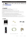
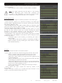
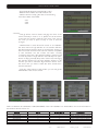
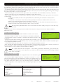
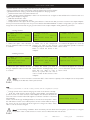
The TWSF 310 CI will be provided with a double DVB-T output that will allow distributing the channels
of the tuned transponders in two consecutive multiplex.
In order to configure the device we will have two selectable modules.
The options of configuration are independent. With the following exceptions:
- The output channel of the second module will be set automatically as the consecutive channel
after the one configured in the first module.
- The output level of the multiplex will be set by the output level configured in the first module.
1.3. Description and connections
The module TWSF 310 CI is used for the reception of free channels that obey the DVB-S/DVB-S2 standards. Each
module allows the reception of two complete transponders in DVB-S (QPSK) / DVB-S2 (QPSK/8PSK), and the
subsequent modulation in DVB-T (COFDM) of them.
A feature of this equipment is its modulator in Vestigial Side Band (or VSB). This modulation can be used to distribute
adjacent channels in one distribution without any interference problem.
Each module has one Loop connector to cascade several modules at input and a Mix connector to do same in output
channels. The output channel is selectable between C2 and C69.
All parameters are programmed by the means of PRO 201 or the EVO or MINI series of field strength meter, and they are
monitored in the display of programmer or in the TFT screen of field strength meter.
TWSF 310 CI has two Common Interface slots.
TWSF 310 CI
1
5
6
7
2
8
9
10
1. Two-colored led*: It indicates the different states of the device.
2. CI: Common Interface.
3. OUT: This connector supplies the modulated channel according to the selected
standard in the module and mixes it with all the signals that it receives through the MIX
connector
4. MIX: Input of mixing of the module.
5. LNC IN: To connect to the LNC or to the LOOP OUT output of the previous module
6. LOOP OUT: To connect to the ANT IN input of the next module.
7. RS 232: Ethernet connector to cascade modules with the RCM 310 telecontrol unit
with the RJ45/RJ45 cable provided.
8. PRO 201: Ethernet connector to make the programming with the programmer.
9. LNC IN 2: Second input to connect to the LNC.
10. DC connectors: It has two connectors for connecting between modules.
3
4
*States of two-colored leds
1. Initialization mode
- Green: main application charged.
- Blinking Green: Completing the initial sequence, at the moment when the module gets initialized, the led will turn
into one of the states the operating mode.
- Red: Phase of initializing the module.
2. Operative Mode
- Green: The system is working properly.
- Orange: At least one critical event has been recorded in the module. The led will only change into green when
the registration of events has been read by the programmer.
- Red: Error or alert detected in the running of the device, the led will be on only as long as the error/alert is
present. Once the error or the alert disappears, the led will change into orange because the error/alert is stored in
the registration of events.
3. Programming mode
- When the module detects an external programmer, the led will blink in the next sequence: green-orange-red.
- Once you leave the programming mode, the led will turn into the corresponding operating mode.
-2-
TWSF 310 CI
version_en_2.0
FTE maximal