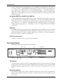
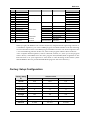
1
Kurzweil KME61
User’s Guide
©2002 All rights reserved. Kurzweil is a product line of Young Chang Co.; Kurzweil and
KME61 are trademarks of Young Chang Co. All other products and brand names are
trademarks or registered trademarks of their respective companies. Product features and
specifications are subject to change without notice.
Part Number:910383-001 Rev. A
The Kurzweil KME61 User’s Guide
CAUTION
RISK OF ELECTRIC SHOCK
DO NOT OPEN
CAUTION: TO REDUCE THE RISK OF ELECTRIC SHOCK,
DO NOT REMOVE THE COVER
NO USER SERVICEABLE PARTS INSIDE
REFER SERVICING TO QUALIFIED SERVICE PERSONNEL
The lightning flash with the arrowhead symbol,
within an equilateral triangle, is intended to alert
the user to the presence of uninsulated
"dangerous voltage" within the product's
enclosure that may be of sufficient magnitude
to constitute a risk of electric shock to persons.
The exclamation point within an equilateral
triangle is intended to alert the user to the
presence of important operating and
maintenance (servicing) instructions in the
literature accompanying the product.
IMPORTANT SAFETY & INSTALLATION INSTRUCTIONS
INSTRUCTIONS PERTAINING TO THE RISK OF FIRE, ELECTRIC SHOCK, OR INJURY TO PERSONS
WARNING: When using electric products, basic precautions should
always be followed, including the following:
1. Read all of the Safety and Installation Instructions and Explanation
of Graphic Symbols before using the product.
2. This product must be grounded. If it should malfunction or break
down, grounding provides a path of least resistance for electric
current to reduce the risk of electric shock. This product is
equipped with a power supply cord having an equipmentgrounding conductor and a grounding plug. The plug must be
plugged into an appropriate outlet which is properly installed and
grounded in accordance with all local codes and ordinances.
DANGER: Improper connection of the equipment-grounding
conductor can result in a risk of electric shock. Do not modify the
plug provided with the product - if it will not fit the outlet, have a
proper outlet installed by a qualified electrician. Do not use an
adapter which defeats the function of the equipmentgrounding
conductor. If you are in doubt as to whether the product is properly
grounded, check with a qualified serviceman or electrician.
3. WARNING: This product is equipped with an AC input voltage
selector. The voltage selector has been factory set for the mains
supply voltage in the country where this unit was sold. Changing
the voltage selector may require the use of a different power
supply cord or attachment plug, or both. To reduce the risk of fire
or electric shock, refer servicing to qualified maintenance
personnel.
4. Do not use this product near water - for example, near a bathtub,
washbowl, kitchen sink, in a wet basement, or near a swimming
pool, or the like.
5. This product should only be used with a stand or cart that is
recommended by the manufacturer.
6. This product, either alone or in combination with an amplifier and
speakers or headphones, may be capable of producing sound
levels that could cause permanent hearing loss. Do not operate for
a long period of time at a high volume level or at a level that is
uncomfortable. If you experience any hearing loss or ringing in the
ears, you should consult an audiologist.
7. The product should be located so that its location or position does
not interfere with its proper ventilation.
8. The product should be located away from heat sources such as
radiators, heat registers, or other products that produce heat.
9. The product should be connected to a power supply only of the
type described in the operating instructions or as marked on the
product.
10. This product may be equipped with a polarized line plug (one
blade wider than the other). This is a safety feature. If you are
unable to insert the plug into the outlet, contact an electrician to
replace your obsolete outlet. Do not defeat the safety purpose of
the plug.
11. The power supply cord of the product should be unplugged from
the outlet when left unused for a long period of time.When
unplugging the power supply cord, do not pull on the cord, but
grasp it by the plug.
12. Care should be taken so that objects do not fall and liquids are not
spilled into the enclosure through openings.
13. The product should be serviced by qualified service personnel
when:
A. The power supply cord or the plug has been damaged;
B. Objects have fallen, or liquid has been spilled into the product;
C. The product has been exposed to rain;
D. The product does not appear to be operating normally or
exhibits a marked change in performance;
E. The product has been dropped, or the enclosure damaged.
14. Do not attempt to service the product beyond that described in the
user maintenance instructions. All other servicing should be
referred to qualified service personnel.
15. WARNING: Do not place objects on the product’s power supply
cord, or place the product in a position where anyone could trip
over, walk on, or roll anything over cords of any type.
Do not allow the product to rest on or be installed over cords of
any type. Improper installations of this type create the possibility of
a fire hazard and/or personal injury.
RADIO AND TELEVISION INTERFERENCE
WARNING: Changes or modifications to this instrument not expressly
approved by Young Chang could void your authority to operate the
instrument.
IMPORTANT: When connecting this product to accessories and/or
other equipment use only high quality shielded cables.
NOTE: This instrument has been tested and found to comply with the
limits for a Class B digital device, pursuant to Part 15 of the FCC
Rules. These limits are designed to provide reasonable protection
against harmful interference in a residential installation. This
instrument generates, uses, and can radiate radio frequency energy
and, if not installed and used in accordance with the instructions, may
cause harmful interference to radio communications. However, there
is no guarantee that interference will not occur in a particular
installation. If this instrument does cause harmful interference to radio
or television reception, which can be determined by turning the
instrument off and on, the user is encouraged to try to correct the
interference by one or more of the following measures:
• Reorient or relocate the receiving antenna.
• Increase the separation between the instrument and the receiver.
• Connect the instrument into an outlet on a circuit other than the one
to which the receiver is connected.
• If necessary consult your dealer or an experienced radio/television
technician for additional suggestions.
NOTICE
This apparatus does not exceed the Class B limits for radio noise
emissions from digital apparatus set out in the Radio Interference
Regulations of the Canadian Department of Communications.
AVIS
Le present appareil numerique n’emet pas de bruits radioelectriques
depassant les limites applicables aux appareils numeriques de la
class B prescrites dans le Reglement sur le brouillage radioelectrique
edicte par le ministere des Communications du Canada.
SAVE THESE INSTRUCTIONS
ii
The Kurzweil KME61 User’s Guide
Young Chang Distributors
Contact the nearest Young Chang office listed below to locate your local
Young Chang/ Kurzweil representative.
Young Chang America, Inc.
P.O. Box 99995
Lakewood, WA 98499-0995
Tel: (253) 589-3200
Fax: (253) 984-0245
Young Chang Co.
178-55 Gajwa-Dong
Seo-Ku, Inchon, Korea
Tel: 011-82-32-570-1380
Fax: 011-82-32-570-1218
404-714
Young Chang Akki Europe GmbH
Industriering 45
D-41751 Viersen
Germany
Tel: 011-49-2162-4491
Fax: 011-49-2162-41744
Young Chang Canada Corp.
250 Victoria Park Ave. Suite# 105
Toronto, Ontario Canada M2H 3P7
Tel: (905) 948-8052
Fax: (905) 948-8172
iii
The Kurzweil KME61 User’s Guide
Contents
Young Chang Distributors........................................................................................................ iii
Chapter 1
Introducing the KME61
Welcome!................................................................................................................................. 1-1
KME61 Overview .................................................................................................................. 1-1
Programs, Setups, and MIDI................................................................................................ 1-1
The Keyboard and Controllers ............................................................................................ 1-1
Modes...................................................................................................................................... 1-2
How to Use This Book .......................................................................................................... 1-2
Chapter 2
Getting Started
Unpacking the Instrument ................................................................................................... 2-1
Placement................................................................................................................................ 2-1
Connecting the Power........................................................................................................... 2-1
Connecting the Audio ........................................................................................................... 2-2
Connecting the Pedals........................................................................................................... 2-2
Turning on the Power............................................................................................................ 2-2
Play Away!.............................................................................................................................. 2-2
Playing the Demo .................................................................................................................. 2-2
The Rear Panel ....................................................................................................................... 2-3
Power Switch ......................................................................................................... 2-3
Power Jack .............................................................................................................. 2-3
Audio Jacks ............................................................................................................ 2-3
Phones Jack ............................................................................................................ 2-3
Switch Pedal Jack................................................................................................... 2-3
Control Pedal Jack ................................................................................................. 2-3
MIDI Ports .............................................................................................................. 2-3
The Front Panel ...................................................................................................................... 2-4
Pitch Wheel ............................................................................................................ 2-4
Modulation Wheel ................................................................................................ 2-4
Volume Slider......................................................................................................... 2-5
Data Slider.............................................................................................................. 2-5
Mode buttons ......................................................................................................... 2-5
Menu (^ / v) buttons.............................................................................................. 2-5
LCD ......................................................................................................................... 2-5
Soft buttons ............................................................................................................ 2-6
Value (+/-) buttons ................................................................................................. 2-6
Group / User Setups select buttons..................................................................... 2-6
Programs / Factory Setups select buttons .......................................................... 2-6
Button Combinations............................................................................................ 2-6
Chapter 3
Program Mode
Program Mode Base Page..................................................................................................... 3-1
Selecting a Program............................................................................................................... 3-1
Playing a Program ................................................................................................................. 3-2
Changing MIDI Channel and Transposition ..................................................................... 3-2
Editing a Program ................................................................................................................. 3-2
Restoring the Default Effects Parameters........................................................................... 3-3
Saving Your Edited Program ............................................................................................... 3-3
iv
The Kurzweil KME61 User’s Guide
Chapter 4 Setup Mode
Setup Mode Base Page .......................................................................................................... 4-1
Selecting Setups ..................................................................................................................... 4-1
Sound Program For Each Zone............................................................................................ 4-2
Zone Muting........................................................................................................................... 4-2
Setup Edit Pages .................................................................................................................... 4-2
Edit Sound Select................................................................................................... 4-3
Edit Key Range ...................................................................................................... 4-3
Edit Note Shift ....................................................................................................... 4-4
Edit Velocity Range ............................................................................................... 4-4
Edit Volume ........................................................................................................... 4-5
Edit Effect Type...................................................................................................... 4-5
Edit Effect Levels ................................................................................................... 4-5
MIDI Parameters ................................................................................................... 4-6
Edit MIDI Channel................................................................................................ 4-6
Edit MIDI Bank and Program.............................................................................. 4-6
Edit MIDI Volume ................................................................................................. 4-6
Saving and Exiting from Editing......................................................................... 4-6
Chapter 5 MIDI Mode
MIDI Mode Base Pages ......................................................................................................... 5-1
MIDI Mode Edit Pages.......................................................................................................... 5-2
Edit MIDI Effect Type ........................................................................................... 5-2
Edit MIDI Effect Levels ........................................................................................ 5-2
Edit MIDI Channel Enables ................................................................................. 5-2
Saving and Exiting ................................................................................................................ 5-3
Chapter 6 Master Mode
Master Tune............................................................................................................................ 6-1
Keyboard Touch..................................................................................................................... 6-1
Managing Memory................................................................................................................ 6-2
Sending Memory Data .......................................................................................................... 6-2
Receiving Memory Data ....................................................................................................... 6-2
System Hard Reset ................................................................................................................ 6-3
Chapter 7 Troubleshooting
Maintenance ........................................................................................................................... 7-1
Common Problems................................................................................................................ 7-1
Power Problems..................................................................................................... 7-1
Audio Problems..................................................................................................... 7-2
MIDI Problems ...................................................................................................... 7-2
Switch Pedal Problems ......................................................................................... 7-3
Control Pedal Problems........................................................................................ 7-3
Use the Right Impedance, Taper, and Range..................................................... 7-3
If None of the Above…......................................................................................... 7-4
Service Centers....................................................................................................................... 7-4
Diagnostics ............................................................................................................................. 7-4
Starting Diagnostics .............................................................................................................. 7-4
Scan Diagnostic...................................................................................................... 7-5
LCD Diagnostic ..................................................................................................... 7-7
Engine Diagnostics................................................................................................ 7-8
v
The Kurzweil KME61 User’s Guide
AUTO Diagnostics ................................................................................................ 7-9
Chapter 8 Reference
Default Program Setup ......................................................................................................... 8-1
Program Parameters.............................................................................................................. 8-1
Program List........................................................................................................................... 8-1
Factory Setup Configuration................................................................................................ 8-7
MIDI Program Selection ..................................................................................................... 8-13
KME61 Effect Types ............................................................................................................ 8-15
MIDI Implementation Chart .............................................................................................. 8-16
Specifications........................................................................................................................ 8-17
vi
Chapter 1
Introducing the KME61
Welcome!
Congratulations, and thank you for purchasing a Kurzweil / Young Chang KME61. You’ve
got your hands on an excellent-sounding and flexible-yet economical-performance
instrument and MIDI controller.
This manual will get you started with your new instrument. You’ll definitely want to keep the
manual handy as you become an advanced user.
KME61 Overview
The KME61 is a great live performance instrument. It has many excellent sounds, including
most of the famous Kurzweil PC2 sounds, already programmed and ready to go. It is also a
convenient MIDI controller ideally suited for controlling additional sound modules and as
input to a sequencer.
Programs, Setups, and MIDI
We’ll use these three terms throughout this manual. They’re the components of the KME61’s
performance features.
Programs are the 256 internal sounds of the KME61.
Setups specify a combination of several performance features. Each setup contains three zones
that can cover any part of the keyboard, or overlap across the entire keyboard. You can
program each zone independently – with different programs, transposition, and MIDI
channels. You can split and layer up to 3 KME61 sounds and control up to 3 external MIDI
instruments at the same time. There are 32 setups, and you can edit and save 16 of these.
You will use the MIDI mode to control external sound modules or interact with a computerbased sequencer
The Keyboard and Controllers
The KME61’s keyboard has 61 standard-sized, organ-style keys. The keyboard is velocitysensitive, meaning the harder (faster) you press a key, the louder the voice (except for organ
voices which, realistically, are not velocity-sensitive). The keyboard is also release-velocitysensitive, meaning that MIDI signals expressing how rapidly a key is released get sent to
external equipment. The keyboard also has monophonic aftertouch which means that the force
used to hold a key down can affect the character of the sound being played.
The KME61 also has several controllers. There are 2 wheels, a slider, and 2 pedals.
The Pitch Wheel (the one on the left) makes the pitch of a sound go higher when the wheel is
rotated upwards, and lower when the wheel is rotated downwards. The Modulation Wheel
controls different characteristics of the sound for each program. Likewise, the Data Slider
controls a different characteristic of the sound for each program.
The KME61 has 2 Pedal Inputs; one is for a Switch Pedal and the other one is for a continuous
Control Pedal. The Switch Pedal is used as a sustain (damper) pedal, and the Control Pedal is
used to control expression.
Introducing the KME61
Caution: Be sure to plug the included switch pedal only into the jack marked “SW Pedal”. Your
KME61 may be damaged if you plug a switch pedal into the “CC Pedal” jack and leave it there for a
long time.
Modes
The KME61 has four operating modes.
When in Program Mode, the KME61 is an easy to understand and operate, stand-alone
performance instrument. To change the sound group, press one of the 16 Group select
buttons. To change the sound in the current group, press a Program select button. Each
Program button has 2 different programs assigned to it. Press the button a second time to
select the second program. The entire keyboard will play the sound shown in the display.
You can read more about Program Mode in Chapter 3.
When in Setup Mode, the KME61 becomes a sophisticated MIDI controller with a built-in
multi-timbral sound module. The keyboard can be split into 3 sections or zones, each playing
a different sound and transmitting on a different MIDI channel. Up to 16 different MIDI
setups can be defined and stored in the built-in nonvolatile memory. You can quickly select
these setups with the 16 sound/setup select buttons. Additionally there are 16 permanently
pre-programmed Factory Setups which cover the most commonly needed sound
combinations. You can read more about Setup Mode in Chapter 4.
MIDI Mode is primarily for use with a computer-based sequencer. In this mode, the
keyboard and performance controls are disconnected from the internal sound module. A
computer-based sequencer or MIDI processor may then be connected between the
keyboard/controls and the sound module. This is sometimes called “local off”. You can read
more about MIDI Mode in Chapter 5.
Master Mode gives access to several parameters that affect the entire instrument. Read more
about Master Mode in Chapter 6.
How to Use This Book
This KME61 User’s Guide is designed to help you get up and running quickly. If you know
electronic instruments and MIDI already and you know pretty much what you want to do
with your KME61, at least read the beginning of Chapter 2. If you need some more help using
the KME61’s many features, you should also read all of Chapters 3 and 4. Chapters 5 and 6
give more information on use with a sequencer and global functions and describe some
typical applications. The remaining chapters provide troubleshooting and reference material
that can be referred to when needed. Finally, don’t underestimate the index. We’ve tried to
think of every word and topic you may need quick access to-it’s the next best thing to a search
engine!
Also, don’t forget to check our web site for any late-breaking information on the KME61 and
other Kurzweil products:
http://www.kurzweilmusicsystems.com/
Above all, have fun, and make lots of great music with your KME61!
1-2
Chapter 2
Getting Started
This chapter will help you hook up your KME61 and learn its basic functions.
Unpacking the Instrument
Carefully remove all of the contents of the shipping box. The box that your KME61 ships in
contains the following:
* KME61
* AC Adapter (9VAC, 2.0A)
* This manual
* Warranty card
* Four adhesive-backed rubber feet
Be sure to keep the box and packing materials, at least during the warranty period, in case
you need to ship the unit for any reason.
Placement
If you are going to be using the unit on a table now or in the future, apply the four stick-on
rubber feet to the bottom. Figure 2-1 shows the recommended locations. Remove the backing
paper from each rubber foot and attach in the recommended locations. It is possible that
these locations could interfere with some keyboard stand’s supports, so check how the
KME61 fits on your stand before applying the rubber feet.
Figure 2-1
Placement of Rubber Feet
Connecting the Power
Turn the power switch (at the rear of the unit) off, then plug the power adapter into the
KME61 and into the wall.
Getting Started
Place the power supply somewhere where it will stay dry and out of the way. We recommend
keeping it on the floor. Never cover the power supply with anything; it needs adequate
ventilation to prevent overheating.
If you’re not in the USA, check that the line-voltage rating of the adapter matches line voltage
in your area.
Connecting the Audio
Connect the Left and Right audio outputs to your audio system or mixer. The outputs are
unbalanced line-level, so use the line or aux inputs to your audio system.
You can also listen to the KME61 using headphones. Plug a pair of headphones into the
Headphones jack on the back of the KME61.
Connecting the Pedals
You can connect an optional switch pedal to the rear panel jack marked SW Pedal. You can
also connect an optional continuous control pedal to the rear panel jack marked CC Pedal.
Turning on the Power
Turn the power switch to the On position. The display and all of the LEDs perform a brief
lightshow, then the Program Mode, Group A (Piano 1) and Program 1 LEDs will light up. The
LCD will also display its initial screen. See Chapter 3 for more detail.
Before playing, we recommend that you slide the Volume control nearly to the bottom and
gradually push the control up while playing the keyboard. This way you won’t cause any
pain or damage if there’s too much gain in your sound system.
Play Away!
Use the Volume slider or your audio system’s volume control to vary the volume. Press a
Program select button once to hear the “red” sound, and twice to hear the “green” sound.
You can also press a Group button to select a different group of related sounds. You can
select any of the KME61’s 256 sounds by using the Group select buttons and Program select
buttons, or by pressing the + and - buttons at the right of the display. The selected sound’s
full name will be displayed on the LCD.
Playing the Demo
To play the demonstration song, press the center and right buttons under the display at the
same time. They are lightly marked as “Demo”. You’ll then see the next screen:
DEMO:Elements
PLAY
EXIT
To play the demo song, press the left “soft button” marked “Play”. The demo song will start
to play. In the display, the word “Play” changes to “Stop”. If you want to stop the song, press
the “Stop” button.
While the song is stopped, you can select other demo songs by using the + and – buttons at
the right of the display.
When you are ready to leave Demo Mode, press the right soft button (“Exit”).
2-2
Getting Started
The Rear Panel
POWER
PEDAL
Switch
LCD
Contrast
AUDIO
MIDI
CC Pedal SW Pedal
In
Thru
Out
Left
Right
Headphones
AC~9V
2.0A
POWER
PEDAL
Switch
LCD
Contrast
AUDIO
MIDI
CC Pedal SW Pedal
In
Thru
Out
Left
Right
Headphones
AC~9V
2.0A
Power Switch
Press the “|” to turn the KME61 on or the “O” to turn it off. If it will be off for a long period
of time, unplug the power adapter from the wall. The KME61’s memory needs no power or
battery to retain information, so there is no advantage in leaving the power on.
Power Jack
Plug the cord from the included power adapter into this jack. Try to always use the adapter
supplied with the unit. Replacements can be ordered from your Kurzweil dealer.
Audio Jacks
The Left and Right audio jacks are used to connect to your audio system. If you are only
planning to use one cable, please use the Left jack to hear a monaural mix of the left and right
signals.
Phones Jack
Plug your headphones in here. You’ll need a “1/4 -inch to-1/8-inch” (or “phone-to-mini”)
adapter plug when using headphones that have a mini plug.
Switch Pedal Jack
Use this jack to plug in the Switch pedal. For this pedal to work properly, it must be plugged
in before power is turned on. The Switch Pedal transmits MIDI controller #64 messages to
internal sounds and external MIDI for each active zone.
Control Pedal Jack
You can plug a Control pedal in here. Not all continuous control pedals are made the same;
we recommend the Kurzweil CC-1. Please see chapter 7 for specifications. The Control Pedal
transmits MIDI controller #11 messages to internal sounds and external MIDI for each active
zone.
MIDI Ports
The KME61 both transmits and accepts most standard (and several specialized) MIDI
messages. In other words, it can serve as both a MIDI master and a MIDI slave.
Using the KME61 as a MIDI Master (MIDI Out)
2-3
Getting Started
Connect a MIDI cable from the MIDI Out port of the KME61 to the MIDI In port of the device
you want to control – another MIDI musical instrument or any device that accepts MIDI, such
as a computer with a MIDI interface or an integrated MIDI In port. This makes the KME61 a
MIDI control device, and you can use it to play other instruments, make recordings using
sequencers, or send MIDI System Exclusive (SysEx) messages for storing setups and effects
settings externally.
Using the KME61 as a MIDI Slave (MIDI In)
Connect a MIDI cable from the MIDI Out port of the instrument or device that you’re using
as the MIDI master to the MIDI In port of the KME61. This makes the KME61 a MIDI slave,
enabling you to play its sounds from any MIDI instrument – keyboard, wind controller, drum
pads, whatever – or to control it via MIDI devices like dedicated sequencers or computers
running sequencing applications. The KME61 can receive 16 independent channels of MIDI
information.
MIDI Thru
The MIDI Thru port passes along whatever MIDI information the KME61 receives at its MIDI
In port (but not the MIDI information that the KME61 itself generates). This makes it easy to
include the KME61 in a chain of multiple MIDI devices, which is a common configuration
when you’re using a computer for sequencing.
LCD Contrast control
Use this to control the LCD’s contrast for best readability.
The Front Panel
The KME61’s front panel is illustrated in detail below.
Mode
Buttons
Menu
Buttons
MODE
Master
Volume
Group/User Setups
Select Buttons
Value
Buttons
LCD
GROUP
Data
USER SETUPS
Piano 1
Piano 2 E Piano 1 E Piano 2 Pop Keys
Strings
Voices
Clavier
Organ
Brass
Program
Synths
Pads
Guitar
Bass
Drums Percussion
Setup
MIDI
PROGRAMS
Master
Panic
Pitch Wheel
Mod Wheel
Master
Volume
Slider
Data
Slider
Demo
Soft
Buttons
FACTORY SETUPS
1
2
3
4
9
10
11
12
5
13
6
7
8
14
15
16
Programs/Factory Setups
Select Buttons
Pitch Wheel
The Pitch Wheel typically performs a pitch bending function with upward motion bending
pitch upwards and downward motion bending pitch downwards. It also transmits MIDI
Pitchbend messages (MSB and LSB) to internal sounds and external MIDI for each active
zone.
Modulation Wheel
The Modulation Wheel may control a different characteristic of the sound. The Modulation
Wheel transmits MIDI controller #1 messages to internal sounds and external MIDI for each
active zone.
2-4
Getting Started
Volume Slider
The Volume Slider affects the level of sound sent to the Line and Phones output.
Data Slider
The Data Slider is used in a similar fashion to the Modulation Wheel. It often controls some
aspect of the sound for the current Program. It also sends MIDI controller #6 to internal
sounds and external MIDI for each active zone. In addition, the Data Slider is used for some
editing functions.
Mode buttons
As described in Chapter 1, the KME61 has 4 main operating modes. The
information is repeated here for your convenience.
Program
When in Program Mode, the KME61 is an easy to understand and operate, standalone performance instrument. To change the sound group, press one of the 16
Group select buttons. To change the sound in the current group, press a Program
select button. Each Program button has 2 different programs assigned to it. Press
the button a second time to select the second program. The entire keyboard will
play the sound shown in the display. You can read more about Program Mode in
Chapter 3.
Setup
When in Setup Mode, the KME61 becomes a sophisticated MIDI controller with a
built-in multi-timbral sound module. The keyboard can be split into 3 sections or
zones, each playing a different sound and transmitting on a different MIDI channel.
Up to 16 different MIDI setups can be defined and stored in the built-in nonvolatile
memory. You can quickly select these setups with the 16 sound/setup select buttons.
Additionally there are 16 permanently pre-programmed Factory Setups which
cover the most commonly needed sound combinations. You can read more about
Setup Mode in Chapter 4.
MIDI
MIDI Mode is primarily for use with a computer-based sequencer. In this mode,
the keyboard and performance controls are disconnected from the internal sound
module. A computer-based sequencer or MIDI processor may then be connected
between the keyboard/controls and the sound module. This is sometimes called
“local off”. You can read more about MIDI Mode in Chapter 5.
Master
Master Mode gives access to several parameters that affect the entire instrument.
Read more about Master Mode in Chapter 6.
Menu (^ / v) buttons
In Edit Mode (Program Edit or Setup Edit) or MIDI and Master modes, you can move among
the menus by pressing these buttons.
LCD
Displays 2 lines of 20 characters each to show the most relevant information in each operating
mode. Chapters 3-6 detail the display contents in the various operating and editing modes.
2-5
Getting Started
Soft buttons
The 3 buttons under the LCD have different functions, which are labeled in the lower line of
the display. These buttons are referred to as “soft” buttons. The buttons are used to select
parameters for editing, as well as zone muting in Setup mode.
Value (+/-) buttons
In Program mode and Setup mode, you can use the + and – buttons to step through the
Programs or Setups. If you have a parameter selected in Program or Setup mode using the
soft buttons, these buttons will allow you to change the value for the parameter. On other
editing screens that only have 1 available parameter, you can also change the value using
these buttons.
Group / User Setups select buttons
While you are operating in Program mode, these buttons allow you to select a Group
(category) of programs. The Group names are shown on the front panel. Once you have
selected a Group, you can select one of the 16 programs in that group using the Programs
buttons.
While you are operating in Setup mode, these buttons select one of the 16 user-created setups.
These are labeled A through P.
Programs / Factory Setups select buttons
There are 8 buttons in this section, but each button can be used to select 2 different programs
or setups. The first 8 programs or setups are labeled 1 through 8, and are shown on the front
panel with a red LED. The next 8 programs or setups are labeled 9 through 16, and they are
shown on the front panel with a green LED. In Program mode, you can select one of the 16
programs available in a group. In Setup mode, you can select one of the 16 factory-created
setups. You can switch between the red and green selections by repeatedly pressing the
button.
Button Combinations
Some combinations of buttons pressed simultaneously perform special functions:
The left two soft buttons under the display perform the Panic function when pressed together.
This will silence “stuck” notes and reset the controllers to bring a runaway MIDI system back
under control. After pressing, you should continue to hold the buttons until all stuck notes
are silenced.
The right two soft buttons enter Demo Mode when pressed together.
described earlier in this chapter.
Demo Mode is
Depending on the edit mode, the + and – buttons to the right of the display may perform a
special function when pressed.
2-6
Chapter 3
Program Mode
To enter Program Mode, press the Program button. Its LED lights to indicate that the panel
and player controls are in Program Mode. Program Mode is automatically selected at
power-up. In Program Mode, the KME61 is a single-zone instrument playing the current
sound program across the keyboard and transmitting on just one MIDI channel. If Program
Mode is reentered after having been in Setup Mode, the current program changes to that
which was selected when Program Mode was last exited. On entry the Group and Program
Select LEDs corresponding to the current sound program light.
Program Mode Base Page
When you are in Program mode, the main display looks similar to this:
A01:Stereo Grand
Ch:12 Oct:+1 Key:D#
On the top line, ʺStereo Grandʺ is the name of the current Sound Program and ʺA01ʺ indicates
that it is Group A Program #01. The LEDs in the Group Select and Program Select buttons
will also indicate the currently selected program. The color of the Program Select LED
indicates whether it is the lower-numbered set (red,1-8) or higher-numbered set (green, 9-16).
Selecting a Program
The current sound program may be changed by selecting a different Group using the 16
Group Select buttons, or a different Program within the current Group using the 8 Program
Select buttons (as described below), or by receiving a MIDI Program Change message on the
current MIDI Channel.
The first press of an unlit Program Select button will light it red and select the lower set of
program numbers (1-8). A second press flips the color to green and selects the higher set.
A quick ʺdouble-clickʺ of an unlit button skips the red selection and goes directly to the green
selection.
Pressing an already lit Program Select button will flip its color and corresponding set.
The + and - buttons will also change the program selection if no soft button is lit. They cycle
first through the programs in the current group, then select the next or previous group and
continue.
Selecting a new group and/or program from the front panel will also send a MIDI bank select
and program change on the current channel if enabled by the Send Program Change MIDI
Parameter. The Bank number, either 0 or 6, will be transmitted as Bank LSB (CC# 32).
Program Mode
Playing a Program
Once you’ve selected a program, you use the KME61’s controls to change the sound while
you play. Let’s call up Group K, Program 1 “Solar Lead”. This is a Synth sound with some
great capabilities. Play the sound for a while. Notice that if you strike the keys harder, the
sound gets brighter. This program, along with most of the KME61 programs, is velocity
sensitive. Now play a key and press down harder on it. You are hearing vibrato, which is a
wavering pitch. This vibrato is being triggered by the aftertouch controller. On this particular
program, that same vibrato can be triggered by the Modulation Wheel. Try it! Now try
moving the Data Slider while playing. This is changing the sound in yet another way.
Finally, try moving the Pitch Wheel. This bends the pitch of all of the notes up or down,
depending on which way you move the wheel.
In addition, you can use the Switch Pedal as a sustain (damper) pedal, much like a piano, and
use the Control Pedal as an expression pedal, much like an organ.
Changing MIDI Channel and Transposition
On the bottom line of the display, ʺCh:12ʺ indicates that MIDI transmit and receive is on MIDI
channel 12. To change this, press the left soft button, which lights in response, then the +
and - buttons to alter the channel. The left soft button LED being on means that the +/buttons are ʺconnectedʺ to the MIDI channel number.
In the sample display shown in this manual, ʺOct:+1 Key:D#ʺ indicates that the keyboard is
transposed up one full octave, and then an additional 3 semitones sharp to the musical ʺkeyʺ
of D#. The range of octave transposition is -2, -1, 0, +1, or +2 octaves. The range of key
transposition is from G (5 semitones flat) to F# (6 semitones sharp). ʺKey:Cʺ means no
additional transpose. Total available transpose range is from -2,G (-30 semitones) to +2,F#
(+29 semitones).
To change either the Octave or Key values, first press the corresponding soft button (which
then lights up). Next, adjust the value with the + and – buttons. The Octave value ʺpinsʺ
when it reaches -2 or +2 but the Key value ʺwraps with carry to the octaveʺ when it passes F#
going up or G going down. However if the ultimate transposition limit is reached (-2,G
going down or +2,F# going up) Key also pins. Pressing + and – at the same time clears
transposition to Oct:0 and Key:C.
The Channel and Transpose setting are remembered as long as the KME61 is in Program
Mode. When you select Setup Mode, the setup parameters govern channel(s) and
transposition. When returning to Program Mode, they revert to what they were when
Program Mode was exited. When you turn on your KME61, Channel is set to 1 and
Transposition is set to Octave:0 and Key:C.
Editing a Program
Program Mode has two Edit Pages for setting up the effects. Unlike the Base Page edits for
Channel and Transpose, these edits can be made permanent and saved with the sound
program.
To access the Program Mode Edit Pages, press the Program Mode button again. Its LED will
flash to indicate that an edit page is active. Changing to Setup, MIDI, or Master modes is
disabled. To leave the Program Mode Edit Pages, press the Program Mode button again. If
3-2
Program Mode
changes were made, the Program Save Dialog is executed first (see below). Otherwise the
display will immediately change back to Program Mode Base Page and the Program Mode
LED will stop flashing.
Edit Effect Type
16 Hall:Chorus
The first Program Mode Edit Page is for selecting the Effect Type (program).
There are 30 Effect Types, each with a unique combination of an ʺA Effectʺand a ʺB Effectʺ.
The number and name of the currently selected Effect Type are displayed on the bottom line
of the LCD. The + and - buttons or Data Slider may be used to scroll through the list of
choices.
Edit Effect Levels
►A: 5%
B: 10%
Edit Effect Levels
A: 5%
►B: 10%
The second Program Mode Edit Page is for adjusting the wet/dry mix for the A and B effects
separately. The arrow “>” indicates which parameter you are adjusting. You can move the
arrow to the A or B parameter by using the up and down menu buttons. The +/- buttons or
Data Slider are used to adjust the level which is pointed by the arrow.
Restoring the Default Effects Parameters
For either of these edit screens, pressing + and – at the same time will bring up this page:
Reload default prog?
Yes
Cancel
Pressing the left soft button (ʺYesʺ) will cause the original factory settings for Effect Type and
Effect Levels for the current program to be reloaded. Pressing the right soft button
(ʺCancelʺ) brings back the previous display.
Saving Your Edited Program
To leave Program Mode Edit, press the Program Mode button (which is still flashing). If the
Effect Type or FX levels were changed from their previous values (including reloading the
defaults), the Program Save Dialog is executed first as shown below. If no changes have
been made, the dialog is skipped, the Program Mode Base page is displayed and the Program
Mode LED stops flashing.
Save Current Prog?
Yes
No
Cancel
The right soft button (ʺCancelʺ) will cancel the exit and return the display to the previous edit
page. The center soft button (ʺNoʺ) will discard the changes to Effect Type and Effect levels
then return the display to the Program Mode Base page.
3-3
Program Mode
The left soft button (ʺYesʺ) will first display the following screen momentarily:
FX settings saved to
A01 Grand Piano
then save the current effect type and level settings to the currently selected sound program.
Finally the Program Mode Base page will be displayed.
3-4
Chapter 4
Setup Mode
To enter Setup Mode, press the Setup button. Its LED lights to indicate that the panel
controls are in Setup Mode. If the LCD display is showing an edit page of the current mode,
it will be necessary to exit to that modeʹs base page (mode LED on continuously) before the
Setup Mode button will be recognized. When in Setup Mode, the KME-61 is a 3-zone
instrument playing up to 3 different internal sound programs at once and perhaps more if an
external module is connected. The zones may overlap or not without restriction. This means
that you can split and layer the zones. Each zone has a number of parameters associated
with it which may be edited. These edited parameter values may then be saved as one of 16
User Setups and recalled at a later time. There are also 16 permanent ʺFactory Setupsʺ.
If Setup Mode is reentered after having been in Program or MIDI Mode, the current setup
changes to that which was selected when Setup Mode was last exited. The mute status of its
zones (see below) is also remembered.
Setup Mode Base Page
The Setup Mode Base LCD page looks similar to this:
FS01 Virtuoso Lead
K15
K13
L01
In the drawing above, “
“ means it is off.
“
US01 User Setup A
None
None
None
” means the soft button in that position is on while
Selecting Setups
While the current setup is not being edited, different setups may be freely selected by using
the User Setups and Factory Setup buttons in the right part of the front panel. The 16 User
Setups buttons select one of the 16 User-created Setups. The 8 Factory Setups buttons select
one of the 16 factory-created preset setups. The first 8 of these (1-8) are indicated by red and
the second 8 (9-16) are indicated by green. Selection and changing the color works just like
Program Mode.
While the Setup Mode Base Page is displayed, the + and - buttons can be used to sequence
through the different setups, factory setups first then user setups.
“FS01” or “US01” are abbreviations of Factory Setup and User Setup, respectively. For the
factory setups, a name is displayed. For the user setups, the setup is identified by its letter
code, A-P.
Setup Mode
Sound Program For Each Zone
The bottom display row shows the Group and Program for each of the 3 zones. For example,
Zone 2 is using Group L and Program 9. A zone can also have no program assigned to it,
and the display shows “None”.
If you want to see the full name of a program that is assigned to a zone, simply press the
associated soft button (which then causes the display format to change). For example, if the
Zone 1 button (left soft button) is pressed, the display changes to:
FS01 Virtuoso Lead
Z1:K15 Sawyer’s Bomb
Zone Muting
The bottom line displays the selected zone and its program name. Z1 stands for Zone1, Z2
for Zone2, and so forth. If the same zone soft button is pressed again, the zone will be
temporarily muted, that is, its sound will be turned off. Press the button a third time and
the sound returns. The zone soft buttons are lit when the corresponding zone sound is on.
It is best to experiment with this to understand exactly how it works.
The mute status is remembered until a different setup is selected. The mute status may also
be saved (see below).
If the same or a different setup button on the front panel is selected again, the display will go
back to the initial page.
Setup Edit Pages
There are a number of Setup Edit pages. The Setup Edit pages are where you will create or
modify setups to suit your performing needs. In addition to selecting programs, you can
adjust the volume, transposition, key range, effects levels, and other parameters for each of
the 3 zones. To edit the currently selected setup, press the Setup button. The Setup Mode
LED will begin flashing. The soft button LEDs continue to display the mute state of each
zone.
When you enter the edit pages, the default mute status of the setup will be reloaded. To exit
the Edit pages, press the Setup button again.
Factory Setups may be edited but the edited version must either be saved in a User Setup slot
or abandoned when a different setup is selected.
The Up and Down menu buttons at the left of the display can be used to select the desired
edit page. The page selection pins when either end of the list is reached. The pages (in
order) are:
1. Edit Sound Select
2. Edit Key Range Low, High
3. Edit Note Shift
4. Edit Vel. Range Low, High
5. Edit Volume
6. Edit Effect Type
4-2
Setup Mode
7. Edit FX A, FX B Level
8. Edit MIDI Channel
9. Edit MIDI Bank, Program
10. Edit MIDI Volume
When an Edit Page is displayed, its name is in the top line and the corresponding parameter
values for the 3 zones are shown on the bottom line (see examples below). As before a zone
soft button may be pressed to select a zone for editing, pressed again to mute, and pressed a
third time to unmute.
The parameter value for the selected zone may be edited as usual by using the + and –
buttons or the data slider. Note that the effect of edits is audible either immediately or when
the next note is played.
Screens, editing rules, and the function of each parameter is described below.
Edit Sound Select
Z1:Edit Sound Select
K15 Sawyer’s Bomb
Initially the above screen appears when the Sound Select parameter is selected. When one
of the zones is selected for editing, the currently selected zone number is shown in the top
line and the full program name is displayed in the bottom line.
The + and - buttons step through the sounds in front panel Group/Program order with None
being first in the sequence and the Data Slider scans through them in front panel
Group/Program order with A01 Stereo Grand being first in the sequence. Additionally the
Group and Program Select buttons may be used to change the selection directly. None
means that this zone does not play any internal sounds. It still may send to external MIDI
devices unless that too is set to None in the Edit MIDI Channel page.
Edit Key Range
Setting the key range allows you to create a setup with keyboard splits (2 separate sounds on
2 sets of keys) or layers (overlapping sounds).
Z1:Edit Key Range
►Lo: C2
Hi: C7
Z1:Edit Key Range
Lo: C2
►Hi: C7
This menu includes 2 paired parameters so “►” is used to indicate the current parameter to
be edited. The “►” can move to the right by pressing the down menu button or to the left
by pressing the up menu button to select Low key or High key. The + and - buttons step and
the data slider scans through the 128 possible keys in chromatic order.
You may also set these directly from the keyboard. First press the + and - buttons at the
same time. The display changes to show the following screen:
Z1:Strike Low Key
►Lo: C2
Hi: C7
4-3
Setup Mode
Next strike the key you wish to specify for the Low Key value. The pointer then moves and
waits for the High Key to be struck:
Z1:Strike Low Key
Lo: C2
►Hi: C7
Note that keys struck to set these parameters do not sound. After both Low Key and High
Key are set, keyboard operation returns to normal.
Edit Note Shift
Note shift is like transposition for each separate zone. It is called note shift because the
MIDI note numbers that would normally be sent for a key are being shifted. You can use this
parameter in 2 creative ways. First, if you are splitting your keyboard, you might notice that a
program in a zone is too high on the right side and too low on the left side. You can shift the
left program up by an octave or two, and shift the right program down by an octave or two,
and get a better result. Second, if you are layering your keyboard, you might want the
“second program” to be up or down an octave, or even some other interval!
Z1:Edit Note Shift
Shift: -12st
Each zone can have a different Note Shift (transpose). The display shows the shift amount
relative to Middle C in semitones for the current zone. The + and - buttons step and the data
slider scans through possible shift amounts.
Edit Velocity Range
Velocity ranges allow you to create a setup where a soft strike on a key will play one program,
while a hard strike on the same key will play a different one!
Z1:Edit Vel Range
►Lo: 1
Hi: 90
Z1:Edit Vel Range
Lo: 1
►Hi: 90
The 2 parameters Velocity Range Low and Velocity Range High define a velocity window.
If a key press produces a velocity inside a zoneʹs window (between the Low and High values),
the note is sent to the zone; if the velocity is outside (less than Low or greater than High),
then no note is sent. It is also possible to specify a reversed range. If a reversed range is
specified (High is less than Low), then the note will be sent if the velocity is outside the range
and not sent if it is inside the range. The arrow indicates which parameter is being edited.
The arrow can be moved between Low and High by using the up and down menu buttons
at the left of the display.
4-4
Setup Mode
Edit Volume
Use this parameter to set the initial levels of your 3 programs. This allows you to “mix” the
sounds to suit your performance.
Z1:Edit Volume
Vol: 110
This parameter adjusts the relative volumes of the internal sounds played by the zones. 127
is maximum and zero becomes Off. The value may be changed using the + and – buttons
and by the Data slider. It is best to set the loudest zone to a value near 127 then set the
others to lesser values.
Edit Effect Type
In program mode, each program has its own Effect Type and effect levels. In setup mode,
the effects are shared among the 3 programs, but you can still set individual effect levels. So,
for example, if an Effect Type has a Chorus and a Reverb, you can adjust the 1st zone to have
Chorus and Reverb added to the sound, and the 2nd and 3rd zones to only have Reverb added
to the sound.
Z*:Edit Effect Type
14 Stage:Chorus
The Effect Type applies to all 3 zones so any of the 3 zone buttons may be pressed to begin
editing. The zone number in the top line changes to an “*” to denote that this page applies
to all of the zones.
The possible values are 30 different effect types (see the appendix for a list).
Edit Effect Levels
As we mentioned above, you can independently set the effects levels for each zone in your
setup. If the Effect Type has 2 names, such as “Stage:Flanger”, the first is the A effect, and the
second is the B effect.
Z1:Edit FX Levels
►A: 5%
B: 10%
Z1:Edit FX Levels
A: 5%
►B: 10%
These parameters independently adjust the wet/dry send levels to each section of the selected
Effect Type. When the Effect Type has only one effect block such as ‘4 Bright Stage’, FX B
level will always be ‘NONE’.
4-5
Setup Mode
MIDI Parameters
The remaining parameters are for use with an external MIDI device connected to the MIDI
Out jack. Their values will have no effect on the KME61ʹs internal sounds.
Edit MIDI Channel
Z1:Edit MIDI Channel
Ch: 1
This screen allows you to set the MIDI channel each zone uses to send notes and controllers
to external devices. “None” means that the zone does not send any MIDI messages.
Edit MIDI Bank and Program
Z1:Edit MIDI program
►Bnk: 0
Pg: 35
Z1:Edit MIDI program
Bnk: 0
►Pg: 35
These parameters allow sending a program and bank change for each zone to external MIDI
devices. Each has possible values of “None” and 0-127. If “None” is specified, then no
message of that type will be sent. The messages are sent immediately while editing and
when the setup is selected while playing.
Edit MIDI Volume
Z1:Edit MIDI Volume
Vol: 90
This parameter adjusts the relative volumes of sounds played by external MIDI devices
controlled by the zones. MIDI Volume (Controller #7) messages are sent to accomplish this.
A value of “None” means that no volume message is sent for that zone. The messages are
sent immediately while editing and when the setup is selected while playing.
Saving and Exiting from Editing
To exit the setup editing pages and return to the Setup Base page, press the Setup button. If
any parameter was changed while on the editing pages, the Save Dialog will begin with this
screen:
Save Current Setup?
Yes
No
Cancel
At this point only the three soft buttons will be recognized as follows:
Cancel - Return to the previous edit page.
No - Go to the Setup Base page without saving the edited values.
Yes - Continue with the next save dialog screen.
4-6
Setup Mode
Select a User Setup:
OK
Cancel
At this point the 16 User Setup buttons will light as follows:
Off - User Setup slots that are currently ʺemptyʺ (have default setup).
On - User Setup slots that have previously been saved to.
Flashing - The currently selected setup if it is a user setup.
Now only the left and right soft buttons and the User Setup Select buttons will be recognized
as follows:
Cancel - Return to the previous edit page.
User Setup - When pressed, that button’s LED will begin to flash. If another button’s LED was
flashing, it will either turn off or stop flashing according to its previous use status.
OK - The edited setup will be saved to the User Setup slot with the flashing LED.
Thus if you simply want to update the current user setup, the left soft button would just be
pressed twice.
Save to User Setup
X
After the save operation, a confirmation screen is displayed briefly then the Setup Base page
is displayed as originally requested.
4-7
Chapter 5
MIDI Mode
MIDI Mode is used when working with a sequencer. When MIDI Mode is selected, the
internal connection from keyboard and controls to internal sound generator is disconnected.
Instead, key presses, control movements, and sound selections are only sent to the MIDI Out
jack. Similarly, the internal sound generator acts like an independent sound module. A
sequencer or other MIDI processor would typically complete a loop from MIDI Out back to
MIDI In recording and altering the messages as they go.
To enter MIDI Mode, press the MIDI button.
controls are in MIDI Mode.
Its LED lights to indicate that the panel
All of the editable MIDI Mode parameters are for setting up the internal sound generator.
They are:
1. MIDI Effect Type (Global for all 16 channels)
2. MIDI Effect Levels (A and B, separate for each channel)
3. MIDI Channel Enable (On and Off for each channel)
MIDI Mode Base Pages
MIDI Mode has two base pages, which are shown below. The up and down menu buttons
may be used to switch between these pages.
1.
---------------2.
Send Program Change
Ch:13 Bnk:101 Pg:113
#1 is a full-screen display of incoming MIDI note activity. Each channel is associated with a
vertical bar with Channel 1 being on the left. Recently received Note-On will cause a bar to
be drawn with an initial height proportional to the Attack Velocity. While the note is held,
the bar will gradually decrease in height. If all notes for the channel turn off, the bar will be
immediately erased. This is an activity indication only; no attempt is made to match the
barʹs dynamics with the envelope of the sound being played.
#2 allows MIDI program changes to be sent manually to any channel. The left soft button
allows the transmit MIDI channel for MIDI Mode to be changed and may be edited with the +
and - buttons in the usual way. Editing the channel does not itself send anything.
The middle and right soft buttons are used to send arbitrary Program Change messages.
Editing either in the usual way causes MIDI Program Change and Bank Select LSB messages
to be sent each time one of the values changes. Besides the usual 0-127 choice, ʺNoneʺ is
available which suppresses sending the corresponding message.
MIDI Mode
MIDI Mode Edit Pages
There are 3 MIDI Mode Edit Pages. An edit page is entered by pressing the MIDI button,
which then begins to flash. The up and down menu buttons cycle among the edit pages.
Pressing the MIDI button again exits back to the last displayed MIDI Mode base page.
Note that Effect Type and Effect Levels set in MIDI Mode only apply to MIDI Mode.
However the Channel Enables also apply to Program Mode as well as MIDI Mode. Selecting
Program or Setup modes resets the effects as specified in the new modeʹs parameters. The
MIDI Mode settings are remembered however and become effective again when MIDI Mode
is re-entered. They may also be saved.
Edit MIDI Effect Type
MIDI Effect Type
14 Stage:Chorus
This page permits the Effect Type for the internal sound generator to be set. The editing
logic is the same as the corresponding screen in Program Mode. See the Appendix for a list
of the 30 available effect types.
Edit MIDI Effect Levels
MIDI Effect Levels
Ch:14 A: 99% B: 28%
This page permits the wet/dry mix for the A and B effects to be set in the internal sound
generator. The levels for each incoming MIDI channel may be set separately.
The left soft button allows a MIDI channel to be selected for level editing. The existing mix
levels for that channel are then displayed. The center and right soft buttons can then be
used to select a level for editing with the + and - buttons and the data slider.
Note that the Effects Type and Effects Levels may be changed from a sequencer via MIDI.
Any MIDI channel that is enabled (see below) may be used. See the MIDI Implementation
chart in the appendix for the controller numbers used to change effects settings.
Edit MIDI Channel Enables
MIDI Channel Enables
Ch:14
On
This screen allows some of the MIDI channels in the internal sound generator to be turned off.
An off channel will not play any notes or respond to any controllers. The left soft button
along with the + and - buttons or data slider selects a channel to examine or change. The
center soft button along with the + and – buttons will toggle the On/Off status of the channel.
5-2
MIDI Mode
Saving and Exiting
To escape MIDI Edit Mode and return to the MIDI base page, press the MIDI Mode button
again. If any parameter was changed while on the editing pages, the MIDI Save dialog will
begin with this screen:
Save Edited Value?
Yes
No
Cancel
At this point only the three soft buttons will be recognized as follows:
Cancel - Return to the previous edit page.
No - Exit MIDI Mode without saving the edited values.
Yes - Save the new MIDI parameter values.
MIDI parameters
Saved.
After the save operation, a confirmation screen is displayed briefly then MIDI Edit Mode is
exited.
5-3
Chapter 6
Master Mode
Master Mode is used to change miscellaneous parameters that affect the entire instrument
and also to select and execute utility functions. When the Master button is pressed, its LED
turns on.
The Up and Down menu buttons at the left of the display can be used to select the desired
Master page. The pages are:
Master Tune
Keyboard Touch
Send Memory Data
Receive Memory Data
System Hard Reset
Each screen and its changing rules is described below.
Master Tune
Master Tune
Oct:+1 Key:C# Tu:+15
The left and center parameters are Master Transpose displayed as Octaves, with a range of -2
to +2, and Keys with a range of G (-5) to F# (+6). These may be changed in the same manner
as in Program Mode.
The right parameter is Master Tune with a range of -99 to +99 cents and may be changed in
the usual way with the + and – buttons and Data Slider.
Master Tune affects the sound engine globally, that is, both locally played notes and incoming
MIDI. However if the combined Transpose (Program Mode) or Note Shift (Setup Mode) and
Master Tune shifts a note beyond the full piano range (A0 - C8), that note may not sound.
Keyboard Touch
Keyboard Touch
Medium
The keyboard may be adjusted for an Easy, Medium, or Hard touch. Medium is an
approximation to the touch response of a standard piano and is suitable for most players.
Easy requires somewhat less force to produce a given loudness and Hard requires somewhat
more. This setting does not affect the after-touch response which is fixed.
Master Mode
Managing Memory
These pages are used to manage the permanent memory which holds the various editable
parameters. Effects settings for Program Mode, User Setups, and MIDI/Master Parameters,
or all of these may be sent to a computer-based sequencer as a data string. Or they may be
received from a sequencer or the memory can be reset to its factory default state.
Sending Memory Data
The following page allows you to select what kind of data will be sent out. Use the + and buttons to scroll through the choices which are displayed on the bottom line. When the
desired data item is displayed, press the right soft button (“Send”) to continue.
Send Memory Data
All
Send
The data item choices are:
All – All three of the data items listed below
Program FX – These are the effects settings for the 256 sound programs.
User Setups – These are the parameters of the 16 user setups.
MIDI/Master – These are the MIDI Mode and Master parameters.
After pressing Send, the following screen is displayed:
Press Start to Send
Start
Cancel
Pressing the left soft button will begin sending the memory data and proceed to the next
screen. The sequencer should be set up and recording before pressing Start. The right soft
button will cancel sending and return to the “Send memory data” page.
Sending Memory
█████
This screen will be displayed while the memory data is being sent out. The bottom line is
used to display a progress bar. When the send operation is complete, the “Send memory
data” page is displayed again.
Receiving Memory Data
Receive Memory Data
Receive
This page allows you to receive previously sent memory data from a computer-based
sequencer. To begin the receive process, press the right soft button which will proceed to
6-2
Master Mode
the next screen:
Waiting for data...
Cancel
You should now start playing a previously recorded memory send from your sequencer
program. If you wish to cancel, press the right soft button to return to the “Receive memory
data” page. Otherwise once the first valid data block is received, the next screen is
displayed:
Receiving...
█████
The bottom line is used to display a progress bar. When receiving is complete, the “Receive
memory data” page is displayed again. Although not shown, the right soft button will still
cancel receiving but the partially loaded memory may be corrupt.
System Hard Reset
This page allows you to erase all of the edits and changes you have made to your KME61 and
thus reset it to its original condition. This is a serious operation which is deliberately made
difficult as a data safety measure.
System Reset
Reset
To begin the reset process, press the right soft button labeled Reset which will display the
following screen:
ERASE EVERYTHING?
Yes
Cancel
The right soft button will cancel the operation and return to the “System reset” page without
erasing anything. The left soft button will proceed to the next screen.
ARE YOU SURE?
Yes
Cancel
The middle soft button will proceed with resetting to the factory defaults and the next screen.
The right soft button will cancel back to the “System reset” screen.
Defaults restored.
After the original factory defaults are restored, this screen is displayed briefly then returns to
Master Tune page which is the first page of Master mode.
6-3
Chapter 7
Troubleshooting
Maintenance
Aside from normal care in handling and use, your KME61requires no regular maintenance.
Clean with a soft cloth dampened with water. Never use abrasives or solvents as they may
damage the unit’s paint, markings, and display lens. There are no batteries inside to
replace-ever. Instead of volatile SRAM used in most other instruments, your KME61 uses
nonvolatile EEPROM for storage, which retains information as captured electrons, without
power.
Common Problems
Below is a list of the most commonly encountered problems and suggestions for solving them.
Power Problems
The LCD and LEDs will display a short startup sequence when power is turned on then
begin normal operation. If nothing at all happens when you turn the power switch on (solid
line “|” pressed in), check these items:
• Power module not plugged securely in wall outlet.
• Cord from power module not fully plugged into KME61.
• Input voltage rating of power module does not match your power system.
• Incorrect or defective power module. The power module specifications are:
9.5VAC, 2.0 amp, center pin positive, 5.5mm OD, 2.5mm ID coax type plug
(Kurzweil Model No. PP95-20).
• Dead wall outlet, power strip, or extension cord.
If there’s evidence of life but operation isn’t quite normal, check these items:
• Input voltage rating of power module does not match your power system.
• Incorrect or defective power module. See above for power module specs. Voltage
or current rating less than specified will cause unusual or intermittent operation.
• Power system voltage abnormally low. Try a different, unused outlet.
• Intermittent operation can be caused by a replacement power module with the
wrong size plug. The correct plug fits snugly into the jack, and doesn’t wobble.
Troubleshooting
Audio Problems
NOTE: When diagnosing audio problems, set the KME61 to play its demo sequence.
If there is no sound from your KME61, check the following:
• KME61 Volume slider moved down. Move the slider to the Up position.
• If a control pedal is plugged in, be sure it is pressed down.
• Volume control on audio system or mixer turned down.
• Signal source selection on audio system or mixer is incorrect.
• Audio cables not securely plugged in at both ends.
• Incorrect type of audio cable.
If you can hear sound but it is low or distorted, look into these possibilities:
• Audio cables not securely plugged in at both ends.
• Low voltage output from power module. Check Power Problems above.
• A received MIDI Volume or Expression message has specified a low volume.
• A control pedal is plugged in but is not pressed down.
• Input to audio system is set for low impedance instead of high impedance.
• Input trim to audio system or mixer is set too low.
MIDI Problems
If you are experiencing problems sending MIDI to an external module, check these:
• MIDI cable not securely plugged in at both ends.
• Wrong MIDI connections. To send MIDI, plug into the KME61’s MIDI Out
connector and the module’s MIDI In connector. Don’t assume; read the jack labels.
• Defective MIDI cable
• MIDI Transmit channel(s) specified by Program Mode or MIDI mode or current
setup does not match that of the receiving device.
If there are problems with the internal sound module receiving MIDI from an external device
like a computer sequencer, try these:
• Transmitting device not sending MIDI on Channel 1.
• MIDI cable not securely plugged in at both ends.
• Wrong MIDI connections. To receive MIDI, plug into the KME61’s MIDI In
connector and the source’s MIDI Out connector.
Prerecorded General MIDI (or GS or XG) sequences may not play through the KME61
correctly. The KME61 is not a General MIDI compatible sound module. These are some of the
differences between the KME61’s internal sound module and a typical General MIDI module:
7-2
Troubleshooting
• Most of the sound program numbers are different.
• Effects setting messages are different.
• Drum sounds are not locked to MIDI channel 10.
Switch Pedal Problems
If you are having problems with the included switch pedal or an aftermarket pedal, check
these:
• Be sure the switch pedal is plugged into the jack marked “SW Pedal”. DO NOT
plug into the “CC Pedal” jack as that may damage the KME61.
• If Sustain is stuck on when using the included pedal, be sure the pedal is plugged
in before switching on the power. Turn power off then on if necessary.
• If the pedal is acting backward (active when up instead of down), turn power off
then on. Be sure the pedal is plugged in before turning power on and don’t use
the pedal until after the unit has completed its power up sequence.
Control Pedal Problems
If you are having problems making a control pedal work properly, give these a try:
• Be sure the control pedal is plugged into the jack marked “CC Pedal”
• Never use a control pedal that has a mono (two circuit) plug. It won’t work and
could damage your KME61.
• If the pedal works backward, operates very abruptly (more like a switch), or not
at all, it’s most likely a wiring problem. See discussion below.
• When using adapter cables to adapt a pedal with two mono cables, verify that the
Y adapter is a stereo splitter type and not just a Y adapter designed to plug two
headphones into a single jack.
• Volume pedals typically won’t work well because of impedance or taper
problems. See below for details. ”Active” volume pedals won’t work at all.
The control pedal must be wired to a single stereo 1/4-inch plug as follows:
• Wiper to Tip connection of 1/4-inch plug
• Top end of resistance element to Ring connection
• Bottom end of resistance element to Sleeve connection
Use the Right Impedance, Taper, and Range
For best results, use a Kurzweil CC-1 control pedal, available from your dealer. The CC-1
meets all of the requirements described below at an economical price.
A control pedal should have an impedance between 5,000 and 100,000 ohms. Less than 5,000
may overload the reference voltage source in the KME61 and interfere with operation of
other controls like the Data slider. More than 100,000 may result in electrically noisy
7-3
Troubleshooting
operation, which may cause your KME61 to send MIDI Controller messages constantly.
The taper of the control should be linear for easy, predictable control. Pedals designed for
volume control will typically have most of their range concentrated in the upper half of travel.
To check taper, run the Control Pedal diagnostic and check the reading when the pedal is
pressed halfway down. If it’s less than about 50, then it has an audio taper and will probably
be difficult to use.
Pedals may have a control range that is less than 0-127. To check this, run the Control Pedal
diagnostic and check the reading at both extremes of pedal motion. Good is a minimum
reading of 0 or 1 and a maximum of 126 or 127. If one end is OK but doesn’t quite reach at the
other end, it may be possible to adjust the linkage or gear to properly center its range.
If None of the Above…
If your problem is not covered above, or none of the suggestions seems to work, first check
back and review the relevant sections of this manual. Many difficulties are just programming
problems caused by inappropriate settings of setup parameters. If you want to be sure that all
of the factory defaults are in place, refer to Hard System Reset in Chapter 6 Master Mode.
Also be sure to check out Kurzweil’s Internet web site for additional KME61 information that
may have been published since this manual was written:
www.kurzweilmusicsystems.com
Service Centers
Contact the nearest Young Chang office listed at the front of this book to locate your local
Young Chang/Kurzweil representative.
Diagnostics
The KME61 has extensive diagnostic software built-in that can be used to test for proper
operation of almost every component. Although this chapter is intended primarily for service
personnel, the diagnostic software can also be helpful for identifying problems with the
cables and external controls.
Starting Diagnostics
1. Turn the power switch off.
2. Press and hold the two buttons marked “+” and “-“ on the front panel.
3. Turn the power switch on while continuing to hold the buttons.
4. Wait until the soft button LEDs begin to flash then release the buttons.
5. On the LCD, “System Diag Wait” will be displayed briefly then the Main Diagnostic
Menu will become active:
SYSTEM DIAG READY
SCAN
LCD
ENGINE
7-4
Troubleshooting
There are three diagnostic groups that may be used as follows:
1. SCAN – This single diagnostic displays the action of every control.
2. LCD – This diagnostic tests the memory of the display module.
3. ENGINE – These diagnostics test various parts of the internal sound board.
To proceed to a diagnostic group, press the associated soft button.
Scan Diagnostic
When the Scan Diagnostic is selected, the initial screen will be like this;
SCAN DIAG
PRESS ANY KEY
At this point, any key press, button press, or control movement will display what moved and
what its value is. Response to each of the controls is described below.
Keys
When a key is pressed very slowly halfway down, the display will first change to:
KEYBRD POS:25
1ST:1 2ND:0 PRS:0
“POS:25” means that key number 25 (Middle C, C4) was pressed. The key numbers range
from 1 (C2) to 61 (C6). “1ST” and “2ND” show the status of the key’s two switches, 0=Off and
1=On. Since the key is halfway down, only the first switch is on. After pressing the
remaining distance, the second switch turns on and the display changes to:
KEYBRD POS:25
1ST:1 2ND:1 PRS:0
Now both key switches are on. After the key is down, pressing harder will activate the
aftertouch (pressure) sensor and the “PSR” value will increase:
KEYBRD POS:25
1ST:1 2ND:1 PRS:78
Firm pressure should be required to get the reading up to 126 or 127. If it is too difficult or
too easy to reach values near 127, a service center may need to adjust the pressure sensitivity.
Finally, when the key is released, the two key switches turn off in the opposite order they
turned on: 2ND first then 1ST and displayed as follows:
KEYBRD POS:25
1ST:0 2ND:0 PRS:0
Properly functioning keys will go through the sequence just described.
If one of the
switches doesn’t turn on or the 0/1 indication flickers, it means that the keyswitches need
cleaning by a service center.
7-5
Troubleshooting
Pitchbend (left) Wheel
Moving the left wheel will trigger a display similar to this:
PITCH BEND
VALUE 101
With the wheel rolled all the way forward, the Value reading should be less than 5; rolled all
the way back, it should be more than 123. When released, it should spring to a value
between 59 and 67 inclusive.
If it is indeed 63, then “CENTER” will also be displayed which indicates perfect centering of
the wheel mechanism. However any value between 59 and 67 inclusive is OK.
Modulation (right) Wheel
Moving the right wheel will trigger a display similar to this:
MODULATION
VALUE 76
With the wheel rolled all the way forward, the value should be no greater than 1. When
rolled all the way back, it should be no less than 126.
Data Slider
When the data slider is moved, the display should change to something like:
DATA SLIDE
VALUE 119
Moving the data slider downward should produce values down to zero. Moving it upward
should produce values up to 127.
Control Pedal
When a control pedal is plugged into the CC Pedal jack and moved, the display should
change to something like:
CC PEDAL
VALUE 56
When the pedal is moved, the values should change from 0 or 1 to 126 or 127. See the
Control Pedal Problems section above if the pedal’s range is less than this. Also check the
value reading when the CC Pedal plug is pulled out, it should change to 126 or 127.
7-6
Troubleshooting
Switch Pedal
If a Kurzweil switch pedal is plugged into the SW Pedal jack, the display should change to
this after the pedal is stepped on once:
SWITCH PEDAL
VALUE 0
The value with be 0 when the pedal is not stepped on and 127 when it is stepped on. Note
that other brands of pedals may work backward: 127 when not stepped on and 0 when
stepped on. The KME61 will work with either type as long as it is plugged in before power
is switched on.
Panel Buttons and LEDs
Pressing any panel button will change the display to show button and LED information.
For example, pressing the Program Mode button will change the display to this:
PROGRAM MENU BUTTON
PROGRAM LED ON
The LED in the Program Mode button should also turn on. All of the non-sound select
buttons with LEDs will behave similarly.
Pressing a button without an LED, like up or down menu or + or - will display the button’s
name but the bottom line will be blank since there is no associated LED.
Pressing a Group or Program button is a little different. For example, pressing the Piano
Group button will change the display to this:
EXTENSION KEY
POS:01-01 LED:RED
The top line will be the same for any of these buttons. The bottom line indicates the button’s
row number first (01, 02, or 03) then the column number (01 - 08). Also the button’s LED
should light. For the Program buttons, the LED color indication should match the LED that
is lit. To change from red to green or green to red, press the same Program button twice.
You can turn all of the LEDs on by pressing the + and - buttons together. The 8 Program
button LEDs should be orange and the others red. Press any other button to turn the LEDs
off again.
To escape the Scan diagnostics, press the up and down
Diagnostic Menu page will now be displayed.
buttons together.
The Main
LCD Diagnostic
On the Main Diagnostic Menu, press the center soft button to start the LCD diagnostic.
While the diagnostic is running, the screen will turn white, then black, then will run through
all of the possible display characters. Let it run through 2 or 3 cycles of this to ensure there
are no problems then press and hold the up and down buttons until the main menu page is
displayed again.
7-7
Troubleshooting
Engine Diagnostics
On the Main Diagnostic Menu, press the right soft button to enter the “Sound Engine”
diagnostic selection menu. The display will change to:
STEP
DIAG ENGINE
AUTO
The left soft button (STEP) allows you to run one diagnostic at a time. The center soft button
(AUTO) will start an automatic sequence of diagnostics that will run repeatedly. Pressing
the up and down buttons together will cancel engine diagnostics and return to the Main
Diagnostic Menu.
When the STEP soft button is pressed, the display changes to:
TEST ROM
START
and the left soft button will be flashing. Press it to begin the diagnostic named in the top
line. Or use the - button to move down and + button to move up the list of available
diagnostics. Pressing the up and down buttons together will cancel engine diagnostics and
return to the Main Diagnostic Menu. Below is a description of each of the available
diagnostics.
1. TEST ROM - This performs a checksum test of the engine software.
2. TEST SROM - This performs a checksum test of the Sound ROM. While
running, a progress bar is displayed. The test takes about 1 minute.
3. TEST SRAM - This tests the read/write memory of the sound engine CPU.
4. TEST DRAM - This tests the delay memory used by the effects processor.
5. TEST MABEL - This tests the main sound generator chip.
6. TEST MIDI PORT - Before running this diagnostic, a MIDI cable MUST be
connected between the MIDI In and MIDI Out jacks of the KME61. Do not
connect to any other MIDI device when running this diagnostic.
7. SEND SINEWAVE - This diagnostic will generate a 1000Hz sinewave audio
signal beginning at a moderately loud volume. Please disconnect or turn down
your audio system before pressing the Start soft button! While running, the
data slider can be moved to change digital level of the sinewave signal from 127dB (very faint) to 0dB (very, very loud!). The sinewave is used with external
test equipment to measure distortion, signal-to-noise ratio, and other audio
parameters. Press the “-“ button to stop the sinewave.
While an Engine Diagnostic is running, the display will change to (using the MIDI test as an
example):
TEST MIDI PORT
CHECK MIDI PORT
After a few seconds, the bottom line will change to show the results:
7-8
Troubleshooting
TEST MIDI PORT
TEST OK
If there was an error, the display would instead show:
TEST MIDI PORT
TEST FAIL CODE:00
In either case, the left soft button may be pressed to run the same test again or a different test
selected with the + and - buttons. As usual, the up and down buttons pressed together
will exit back to the Main Diagnostic Menu page.
AUTO Diagnostics
If AUTO is selected in the Engine Diagnostic Menu, all of the above diagnostics including the
sinewave are run in sequence repeatedly until stopped. Please turn down or disconnect
your audio system before selecting! Each iteration takes about 90 seconds. This mode is
useful for “burning in” a unit at the factory or after a repair has been made. Note that a
MIDI cable must be connected from MIDI Out to MIDI In for the MIDI test to pass.
If a test fails, the sequence will pause for a couple of seconds so the failure message can be
seen, then it will continue. A Fail Counter is displayed in the upper right corner of the
screen which increments every time a test fails.
To stop the test sequence, press and hold the up and down
recognized between the tests.
buttons until they are
7-9
Chapter 8
Reference
Default Program Setup
The Program Setup defines the MIDI characteristics of Program mode.
You also set the effects parameters for each of the 256 sounds while editing the Program.
Program Parameters
Below is a list of the parameters and default values for the Program Mode. The shaded
parameters are not available in Program mode.The default values of the effects parameters
vary according to which sound is selected.
ZONE 1
Sound Group and Program - According to sound selected
Key Range Low - C2
ZONE 2
ZONE
None
None
-
-
Key Range High - C6
-
-
Vel. Range Low - 1
-
-
Vel. Range High - 127
-
-
Note Shift - Initially 0 then as edited
-
-
-
-
Volume - 127
FXA Level - According to sound selected then as edited
FXB Level - According to sound selected then as edited
-
-
MIDI Channel - Initially 1 then as edited
None
None
MIDI Program - According to sound selected
None
None
MIDI Bank -
None
None
Off
Off
According to sound selected
Zone Mutes - On
FX Type - According to sound selected
Program List
Below is a list of the 256 sounds (Programs) available from the internal sound module. The
list includes the control assignment and the factory default effects setting for each sound.
Reference
Group A Piano 1
Data Slider
MW
Mpress
FX Type
1
Stereo Grand
4. Bright Stage
2
Classical Grand
7. Large Hall
3
Dynamic Grand
3. Stage
4
Warm Grand
6. Bright Hall
5
Solo Grand Piano
4. Bright Stage
6
Concert Piano
4. Bright Stage
7
Mono Grand Piano
4. Bright Stage
8
Piano for layers
3. Stage
9
Sweet Ivories
3. Stage
10
Nice Touch Grand
3. Stage
11
Piano Solitude
1. Room
12
Piano Recital
5. Hall
13
Full Bloom Piano
6. Bright Hall
14
Pianetta
3. Stage
15
Suite Piano
1. Room
16
Dreamy Piano
6. Bright Hall
Group B Piano 2
Data Slider
MW
Mpress
FX Type
1
Hard Rock Piano
1. Room
2
Rock Piano
1. Room
3
Grand Piano 440
4. Bright Stage
4
Mono Stage Piano
1. Room
5
Dyn Stage Piano
1. Room
6
Ragtime Piano
1. Room
7
Tack Piano
8
Piano & String
9
Basement Upright
4. Bright Stage
10
Chiano
4. Bright Stage
11
Way Back Piano
12
Dance Piano
13
Cloud Ride Piano
14
Organic Piano
Vox timbre
15
Piano & Wash
Cutoff, Pad layer
3. Stage
16
Piano & Vox Pad
Cufoff, Vox layer
4. Bright Stage
Group C E Piano 1
1. Room
LoPass Freq
String Level
4. Bright Stage
7. Large Hall
Highpass filter
1. Room
8. Large Bright Hall
9. Deep Space
Data Slider
MW
1
Classic E Piano
Timbre
Tremolo Depth
Mpress
FX Type
1. Room
2
Serious Classic
Tremolo Rate
Tremolo Depth
2. Bright Room
3
That's 70's E Pno
Tremolo Depth
1. Room
4
Hard E Piano
Tremolo Depth
2. Bright Room
5
Lounge E Piano
Timbre
Tremolo Depth
1. Room
6
Dynamic E Piano
Hi Freq Cut
Tremolo Depth
4. Bright Stage
7
Soft E Piano
LoPass Freq Cut
Tremolo Depth
4. Bright Stage
8
Hybrid E Piano
Timbre
Tremolo Depth
1. Room
9
Mello E Piano
Tremolo Rate
Tremolo Depth
1. Room
10
Tines Square
Tremolo Rate
Tremolo Depth
1. Room
11
Brunch In Seoul
Tremolo Rate
Tremolo Depth
1. Room
12
Classy Roadz
Tremolo Rate
Tremolo Depth
1. Room
13
Barking Tines
Tremolo Rate
1. Room
14
Clean and Soft
Filter cutoff
15
Ballad Keys
Tremolo Rate
Tremolo Depth
Tremolo
Depth:duller
Tremolo Depth
16
Lotus Keys
Tremolo Rate
Tremolo Depth
6. Bright Hall
8-2
7. Large Hall
8. Large Bright Hall
Reference
Group D E Piano 2
Data Slider
MW
1
My Best Wurly
Tremolo Rate
Tremolo Depth
3. Stage
2
Big Red Wurly
Tremolo Rate
Tremolo Depth
1. Room
3
Brkfst in Korea
Timbre
Tremolo Depth
2. Bright Room
4
Soft Wurly
Timbre
Tremolo Depth
2. Bright Room
5
Wurly Road
Timbre
Tremolo Depth
1. Room
6
Pearly Keys
Timbre
Tremolo Depth
1. Room
7
Digital E Piano
Timbre
Tremolo Depth
1. Room
8
Ballad E Piano
Timbre
Tremolo Depth
7. Large Hall
9
Soft Ballad
Tremolo Rate
Tremolo Depth
6. Bright Hall
10
70's FM Tines
Filter cutoff
Tremolo Depth
1. Room
11
90's FM Ballad
Alternative attack
Vibrato Depth
1. Room
12
Chorus Rock Pno
13
Bright Pianotone
Tremolo Rate
Tremolo Depth
8. Large Bright Hall
14
Family Portrait
Tremolo Rate
Tremolo Depth
18. LargeHall:Chorus
15
Harpsi-Piano
Vib/Tremolo Rate
Vib/Tremolo Depth
8. Large Bright Hall
16
Fantasy Keys
Timber/Amp control
Vibrato Depth
8. Large Bright Hall
Group E Pop Keys
Mpress
FX Type
13. BrightRoom:Chorus
Data Slider
MW
1
C3PO
Timbre
Tremolo Depth
14. Stage : Chorus
2
Digital E Grand
Timbre
Tremolo Depth
12. Room :Chorus
3
Rock E Grand
Timbre
Tremolo Depth
12. Room :Chorus
4
FantAsmAtron
Timbre
Tremolo Depth
5
Atmaz
Timbre
Tremolo Depth
14. Stage : Chorus
6
Celestial Comet
Treble Cut
Tremolo Depth
22. Stage
7
Comp Time
LoPass Freq
Vibrato rate, Depth
8
Ruth Buzzy
LoPass Freq Cut
Vibrato
9
Janet's Comp
Filter Cutoff
Vibrato Depth
10
Mild Sheen
Filter Cutoff
Vib/Tremolo Depth
11
Scrape Glass
Filter Cutoff
Vibrato Depth
12. Room :Chorus
12
Air Society
Filter Cutoff
Vib/Tremolo Depth
22. Stage
13
Push Air
Filter Cutoff
Filter LFO Depth/rate
14
Dronin'
Bandpass freq
BandPass Width
15..Brit Stage:Chorus
15
Alien Salt Mine
Env control:Attack
Vibrato Depth
26. DeepSpace :Flanger
16
Imperfect Storm
Cutoff Freq: Layer1
Resonance
20. DeepSpace :Chorus
Group F Clavier
Mpress
FX Type
1. Room
: Flanger
4. Bright Stage
Vibrato
22. Stage
: Flanger
22. Stage
: Flanger
3. Stage
: Flanger
9. Deep Space:Flanger
Data Slider
MW
1
Clav Classic
Bass Level
HiPass LFO Depth
Mpress
FX Type
2
Touch Clav
Timbre
3
Dual Wah Clav
Bandpass Width
4
Harpsichord
Timbre
5
Modern Harpsi
Timbre
6
CrystalClavchd
Treble Cut
7
Accordion
Timbre
Swell
8
Celesta
Timbre
1. Room
9
Mod Clavier
Timbre:Para EQ amp
10
Belly Celeste
Trelmolo rate
LoPass Freq
Timbre: fade
bright layer
Tremolo Depth
11
Harpsichordion
Timbre:Para EQ freq
Tremolo Depth
4. Bright Stage
12
Circus Keys
LFO rate control
Vib/Tremolo Depth
13
Cosmic Calliope
LFO rate
Tremolo/Vibrato
14
Calliope Keys
LFO rate
Tremolo/Vibrato
3. Stage
15
Chiff Attack
Timbre:Para EQ freq
Vibrato Depth
7. Large Hall
16
Spaced Harmonix
Timbre:Amp control
Vibrato Depth
4. Bright Stage
1. Room
BandPass LFO Rate
1. Room
21. Room : Flanger
Decay Control
Lopass Freq,
Layer Detune
Vibrato
1. Room
8. Large Bright Hall
5. Hall
Swell
1. Room
1. Room
5. Hall
5. Hall
11. PingPong
8-3
Reference
Group G Organ
Data Slider
MW
Mpress
FX Type
1
The Reverend's
LoPass Freq
Rotary Ramp Speed
14. Stage : Chorus
2
Ballad Of 3 Bars
Perc Xfade
Rotary Ramp Speed
3. Stage
3
Prog Rocker's B
Perc Xfade
Rotary Ramp Speed
3. Stage
4
All Out Full On
Rotary Ramp Speed
7. Large Hall
5
Grungy Overdrive
Rotary Ramp Speed
1. Room
6
Uptown Gospel
Para EQ Freq
Rotary Ramp Speed
7
Retro Roto
Xtra Hi Freq
Rotary Ramp Speed
1. Room
8
Pipe Organ
Layer Xfade
LFO rate control
Vib/Tremolo Depth
3. Stage
12. Room:Chorus
5. Hall
9
BackgroundOrgan
10
Mello Tone Wheel
LFO rate control
Vib/Tremolo Depth
11
Piped Organ
Vibrato rate
Vibrato Depth
12
Playful Piper
More breath
Delayed Vibrato
4. Bright Stage
13
Peter's Pan
Timbre(air)
Vibrato Depth
3. Stage
14
Imaginary Flute
Chiffer attack
Delayed Vibrato
15
Bright Koreana
Timbre
Vibrato Depth
17. Bright Hall:Chorus
16
Bouncin' BassBall
LFO rate control
Vib/Tremolo Depth
20. Deep Space Chorus
Group H Brass
3. Stage
Pitch Bend
Pitch Bend
3. Stage
4. Bright Stage
Data Slider
MW
Mpress
FX Type
1
Big Brass
LoPass Freq
Vibrato Depth
Swell Env & Pitch
3. Stage
2
Saxes/Trumpets
Lopass Freq
Vibrato Depth
Swell Env & Pitch
1. Room
3
Split Section
Lopass Freq
Vibrato Depth
Swell Env & Pitch
1. Room
4. Bright Stage
4
Broadway Brass
Lopass Freq
Vibrato Depth
Swell Env & Pitch
5
Trombones
Timbre
Vibrato Depth
Swell Env & Pitch
4. Bright Stage
6
Bari/Tenor Sect
Lopass Freq
Vibrato Depth
Swell Env & Pitch
1. Room
7
Solo Tenor Sax
Lopass Freq
Vibrato Depth
Vibrato Depth
3. Stage
8
Williams Brass
Lopass Envelope
Swell Envelope
6. Bright Hall
9
Goosed Riff Sect
Pitch Bend
3. Stage
10
Fatso Sax
Layer 3 Amplitude
Vibrato Depth
Disable
Tsax octave layer
Delayed Vibrato
Pitch Bend
3. Stage
11
Big&Beefy Saxes
Enable layer
Vibrato Depth
12
Goosed Unison
Pitch Bend
1. Room
13
Anabrass
Timbre Control
Vibrato Depth
3. Stage
14
Honk'n Dyn Sax
Switches programs
Vibrato Depth
1. Room
15
Saxy Lush
16
Classical Brass
Group I
Envelope: release rate
1. Room
Vibrato Depth
Vibrato
5. Hall
Vibrato Depth
Envelope Control
5. Hall
Mpress
FX Type
Strings
Data Slider
MW
1
Lyrical Strings
Brightness
Attack Switch
4. Bright Stage
2
Slow Strings
Brightness(Cut)
Slow Vibrato
7. Large Hall
3
Marcato Strings
Brightness(Cut)
Envelope Switch
3. Stage
4
Layer Strings
Brightness
Attack Control
2. Bright Room
5
Fast Strings
Timbre
Layer Switch
4. Bright Stage
6
Touch Strings
Timbre
Tremolo
4. Bright Stage
7
Velocity Strings
Timbre
Layer Switch
4. Bright Stage
8
Phantom Strings
Timbre
Envelope Control
7. Large Hall
9
Fast Vtrig Rosin
Timbre:dullar
Envelope:attack rate
2. Bright Room
10
Emotional String
Timbre:dullar
3. Stage
11
Octave Strings
Timbre:dullar
12
Emphatic Strings
Timbre:dullar
Switch Layers
Disables
lower-pitched layer
Switches layers
13
Rosin Section
Timbre:dullar
Switches layers
3. Stage
14
Resolute Section
Switches layers
4. Bright Stage
15
Tender Strings
Switches layers
6. Bright Hall
16
Flute & Strings
Modulation sweep
9. Deep Space
8-4
Timbre:dullar
Resonance,
brightness
4. Bright Stage
9. Deep Space
Reference
Group J Voices
Data Slider
MW
Mpress
FX Type
1
Ooh><Aah
Timbre
Vibrato
Layer Xfade
3. Stage
2
Doo><Daa
Timbre
Vibrato
Layer Xfade
3. Stage
3
Baa stacc. Bop
Envelope Control
Vibrato
Swell
3. Stage
4
Doo stacc. Doop
Envelope Control
Vibrato
Swell
6. Bright Hall
5
Daa stacc. Dot
Envelope Control
Vibrato
Swell
1. Room
Swell
6
Scatman
Envelope Control
Vibrato
7
The croons
Timbre
Vibrato
8
Cathedral Vox
Brightness(Cut)
Brightness(Cut)
5. Hall
9
Bright Voices
Timbre
Vibrato Depth
3. Stage
10
Crystal Voices
LFO rate control
11
Vox & Organ
Disable organ layer
12
BIG Ooh Voices
Vibrato rate
Vib/Tremolo Depth
Envelope:
release rate
Vibrato Depth
20. Deep Space:Chorus
13
BIG Voices
Vibrato rate
Vibrato Depth
27. 4Tap:Chorus
14
Bright Syn Vox
Timbre
Vibrato Depth
10. 4 Tap Dly
15
Vox Orgel
Timbre Control
Vibrato Depth
6. Bright Hall
16
Vox & Strings
Vibrato rate
Vibrato Depth
5. Hall
Data Slider
MW
Mpress
Group K Synths
1. Room
20. Deep Space:Chorus
17. Bright Hall:Chorus
17. Bright Hall:Chorus
FX Type
1
Solar Lead
LoPass Freq
Vibrato Rate, Depth
Vibrato Rate, Depth
2
Vox Lead
LoPass Freq
Vibrato Rate, Depth
Vibrato Rate, Depth
14. Stage : Chorus
20. Deep Space:Chorus
3
Alazawi
LoPass Envelope
Vibrato Rate, Depth
Vibrato Rate, Depth
28. Pingpong:Chorus
4
Slo Wood Flute
Breath Noise
Tremolo Depth(Cut)
5
Groove Bass
LoPass Freq
Vibrato Depth
Vibrato Rate
21. Room : Flanger
6
1/3 Pulse Bass
LoPass Freq
Vibrato Rate, Depth
7
Sweeper Bass
LoPass Freq
Vibrato Depth
Vibrato Depth
12. Room : Chorus
8
Lowdown Bass
LoPass Freq
Vibrato Rate, Depth
Vibrato Rate, Depth
21. Room : Flanger
19. LargeBHall:Chorus
19. LargeBHall:Chorus
9
Subdivide
Filter cutoff
Vibrato Depth
10
Rezzy Bass/Poly
Filter cutoff
Vibrato Depth
17. Bright :Chorus
11
Technicolor
Filter cutoff
Vibrato Depth
29. 4Tap DLY : Flanger
12
Elan Lead
Filter cutoff
Vibrato Depth
Vibrato
13
Sun Sport Lead
Filter cutoff
Vibrato Depth
Vibrato
14
Dinosaur's Lead
Vibrato Depth
Vibrato
15
Sawyer's Bomb
BandPass width
Vox pitch bend
16
Reverse FeedBack
Filter cutoff
Vibrato Depth
Group L Pads
Filter cutoff/resonance
12. Room : Chorus
5. Hall
16. Hall:Chorus
1. Room
15 Stage :Chorus
3. Stage
Data Slider
MW
Mpress
FX Type
1
Rez Aah Pad
LoPass Freq
Vibrato
Swell
9. Deep Space
2
Crypt
Timbre
Vibr, Pan/Fltr LFO
Vibr, Pan/Fltr LFO
3
Meteor Strings
LoPass Freq
Vibrato, Trem Depth Brightness
7. Large Hall
4
Orch Pad
LoPass Freq
Vibrato
Horn Layer Swell
8. Large Bright Hall
5
Neptune
"Chiff" Level
Tremolo Depth
6
Analogy
LoPass Freq
Vibrato Rate, Depth
Swell
5. Hall
7
Dream Catcher
LoPass Freq
Filter LFO Depth
Swell
8. Large Bright Hall
8
U say Tomita…
Vibrato/Trem
Vibrato/Trem
3. Stage
9
Poseidon
Tremolo Depth
Vibrato/Trem
7. Large Hall
10
Analogica
LoPass Freq
Filter cutoff,
treble boot
Resonace
Vibrato Depth
Filter cutoff
11
Anti Rez
Filter cutoff
Vibrato Depth/rate
12
Spider's Web
Filter cutoff
13
Ethereal Strings
Filter cutoff in Layer2
14
FreeResAhh Notch
Filter cutoff
Filter Sweep
BandPass
width&Freq
Crossfade,
layer detune
15
Ooh><Ahh Pad
Resonace
Vibrato Depth
16
Vocalicious
Timbre:duller
Deffierent envelope
9. Deep Space
8. Large Bright Hall
10. 4Tap Dly
2. Bright Room
Volume
7. Large Hall
5. Hall
Treble Boost
5. Hall
Filter cutoff,
layer xfade
8. Large Bright Hall
5. Hall
8-5
Reference
Group M Voices
Data Slider
MW
Mpress
1
Acoustic Guitar
EQ Ctr Freq
Vibrato
Vibrato Rate
FX Type
2
Strummer 12 Str
Brightness
Vibrato
3
Rich 6 String
Timbre
Vibrato
4
12 String Guitar
EQ Ctr Freq
Vibrato
5
Chorus Elec Gtr
Timbre
Tremolo Depth
6
Elec 12 String
Timbre
Tremolo
5. Hall
7
Jazzy Frets
Attack Control
Tremolo
1. Room
8
Lead Rock Gtr
Timbre
Vibrato
9
Titanium Guitar
More body
Muted Guitar
10
Latin Lover
Disables knock layer
Muted Guitar
3. Stage
11
Roto 12 String
Filter cutoff
Swaps layers
8. Large Bright Hall
1. Room
3. Stage
5. Hall
Vibrato Rate
3. Stage
3. Stage
Feedback Amount
8. Large Bright Hall
4. Bright Stage
12
Electric 12
Enables layer
3. Stage
13
Twangy Guitar
Filter cutoff
Vibrato Depth
4. Bright Stage
14
Chr Elec & Mute
Filter cutoff
Vibrato Depth
5. Hall
15
Comp Chr E Gtr
Filter cutoff
Vibrato Depth
4. Bright Stage
16
Trashed Tubes
Filter cutoff
Vibrato Depth
8. Large Bright Hall
Group N Voices
Data Slider
MW
Mpress
1
Round and Wound
LoPass Freq(Cut)
Vibrato
Vibrato
3. Stage
2
Punch Bass
LoPass Freq
Vibrato
Vibrato
3. Stage
3
Two Finger Bass
LoPass Freq(Cut)
Vibrato
Vibrato
0. No Effect
4
Dual-Tri Bass
Timbre
Vibrato
Vibrato
0. No Effect
5
Clav o' Bass
Timbre
Vibrato
Vibrato
21. Room : Flanger
6
Fret Not Bass
Timbre
Vibrato
Vibrato
16. Hall: Chorus
7
Upright Bass 1
Timbre
Vibrato
1. Room
8
Upright Bass 2
Timbre
Vibrato
1. Room
9
Gimme The Finger
Filter cutoff
Vibrato Depth
Vibrato Depth
0. No Effect
10
Bright E Bass
Filter cutoff
Vibrato Depth
Pitch Bend
11
Bright A Bass
Vibrato rate
Vibrato Depth
Pitch Bend
12
Triangle Bass
Filter cutoff
Vibrato Depth
Vibrato Depth
12 Room:Chorus
13
Yow Bass
Filter cutoff
Vibrato Depth
Vibrato depth/rate
21 Room:Flanger
14
Mono Synth Bass
Filter cutoff
Vibrato Depth
Vibrato depth/rate
12 Room:Chorus
15
400 HP Bass
Filter cutoff
Vibrato Depth
Resonance
12 Room:Chorus
16
Base in Face
Filter cutoff
Vibrato Depth
Resonance
12 Room:Chorus
Mpress
Group O Drum
FX Type
12 Room:Chorus
3. Stage
Data Slider
MW
1
Studio Drum 1+2
Timbre
Layer Switch
1. Room
2
Studio Drum 3+4
Timbre
Layer Switch
1. Room
3
Ambient Rock Kit
Timbre
Layer Switch
3. Stage
4
Coliseum Kit
Timbre
Pitch control
5. Hall
5
Resonant Traps
Timbre
Pitch control
1. Room
6
Tripkit/Trashkit
Timbre
Layer Switch
1. Room
7
Beat Box
Timbre
Layer Switch
1. Room
8
Electro Kit
Timbre
Layer Switch
1. Room
9
Radio Kings/Rods
Timbre
2nd kit Enable
1. Room
10
Ripper Kit/Vynyl
Shaper;timbre
2nd kit Enable
3. Stage
11
LA Drums/Brk Bt.
Timbre
2nd kit Enable
1. Room
12
Compact/Raw Kit
Shaper;timbre
2nd kit Enable
6. Bright Hall
13
Tubetraps/lb.der
Shaper;timbre
2nd kit Enable
1. Room
14
Acoustic/HipKit
Shaper;timbre
2nd kit Enable
4. Bright Stage
15
Dirt/Triphop Kit
SumPumpKit
MWSus
Timbre
2nd kit Enable
5. Hall
Timbre
Drone layer
16
8-6
Pitch Control
FX Type
5. Hall
Reference
Group P Percussion
Data Slider
MW
1
Virtuoso Perc
Pitch Control
Muting
Mpress
FX Type
4. Bright Stage
2
Rhythm Maker
Pitch Control
Sample Start
1. Room
3
Woody Marimba
Sample Start
Layer switch
5. Hall
4
African Marimba
Lyr Enable(Shaker)
2. Bright Room
5
Vibes
Lyr Enable(Sine)
3. Stage
6
New Fluid Vibes
7
Aborigine Jam
8
Drums 'n Belles
9
Marimba
10
11
8. Large Bright Hall
3. Stage
Sample Start
3. Stage
Timbre:duller
Alternative Attack
1. Room
Milky Way Vibes
Trelmolo rate
Tremolo Depth
Percussionist
Shaper; timbre
Alternative Attack
12
Carnival
Filter cutoff
Alternative Attack
2. Bright Room
13
Primitive Perc
Disables layer
Alternative Attack
1. Room
14
Bunch of Perc
Pitch change
Enable Mpres
pitch bend
Enable Mpres
pitch bend
Alternative Attack
15
Perc Party
16
Perc Circle
20. Brit Stage:Flanger
Alternative Attack
Alternative Attack
3. Stage
1. Room
Pitch bend with
Data slider
Pitch bend with
Data slider
1. Room
1. Room
When you play the KME61 with a master keyboard, computer-based sequencing software or
a standalone sequencer, you can use MIDI program and bank numbers from the following
list. Note that the list shows true MIDI program numbers from 0 to 127. Some sequencers use
a 1 to 128 numbering scheme. In that case, add 1 to the program number shown in the list.
A few computer-based sequencers, such as Cakewalk, Cubase, etc., allow you to use program
names directly. The KME61 uses the same program name/number/bank assignment as the
Kurzweil PC2 so set your sequencer to ʺPC2 modeʺ to take advantage of this feature. (Note
that the KME61 does not provide the KB3 Mode programs that are in the PC2.)
Factory Setup Configuration
Virtuoso Lead
Factory Setup
01
Zone 1
Zone 2
Zone 3
Sound
K15
K13
L01
Key Low
C2
C4
C2
Key High
B3
C#7
C#7
Note Shift
0
0
0
Vel Low
81
1
1
Vel High
127
127
127
Volume
127
122
127
28 - PingPong + Chorus
FX Type
FX Level
0 / 52%
34 / 0%
31 /43%
8-7
Reference
Jazz Gig
Factory Setup
02
Zone 1
Zone 2
Zone 3
Sound
A01
N07
None
Key Low
C4
C2
-
Key High
C#7
B3
-
Note Shift
-12
0
-
Vel Low
1
1
-
Vel High
127
127
-
Volume
127
127
-
4 - Bright Stage
FX Type
FX Level
12%
-
Cocktail Hour
Factory Setup
03
Zone 1
Zone 2
Zone 3
Sound
G09
N14
G02 (Muted)
Key Low
C4
C2
C2
Key High
C#7
B3
C#7
Note Shift
-12
0
0
Vel Low
1
1
1
Vel High
127
127
127
Volume
127
127
109
04 - Bright Stage
FX Type
FX Level
12%
0%
22%
Salsa Caliente
Factory Setup
04
Zone 1
Zone 2
Zone 3
Sound
B02
N11
P01
Key Low
C4
C2
C2
Key High
C#7
B3
C#7
Note Shift
-12
0
0
Vel Low
1
1
59
Vel High
127
127
127
Volume
127
127
109
03 - Stage
FX Type
FX Level
8-8
0%
20%
0%
34%
Reference
Evocative
Factory Setup
05
Zone 1
Zone 2
Zone 3
Sound
L12
K08
J14
Key Low
C4
C2
C2
Key High
C#7
B3
C#7
Note Shift
0
0
-12
Vel Low
1
1
0
Vel High
127
127
127
Volume
127
127
86
10- 4 Tab Delay
FX Type
FX Level
56%
0%
58%
Angula Mass
Factory Setup
06
Zone 1
Zone 2
Zone 3
Sound
K10
N16
J14
Key Low
C4
C2
C2
Key High
C#7
B3
C#7
Note Shift
0
0
-12
Vel Low
1
1
0
Vel High
127
127
127
Volume
127
104
86
10 - 4 Tap Delay
FX Type
FX Level
14%
0%
18%
Funky Bunch
Factory Setup
07
Zone 1
Zone 2
Zone 3
Sound
C02
K05
H12
Key Low
C4
C2
B3
Key High
C#7
B3
C#7
Note Shift
-12
0
-12
Vel Low
1
1
89
Vel High
127
127
127
Volume
127
127
127
23 - BritStage + Flanger
FX Type
FX Level
14 / 0%
0 / 0%
44 / 0%
8-9
Reference
Set Adrift
Factory Setup
08
Zone 1
Zone 2
Zone 3
Sound
E07
G14
L14
Key Low
C-1
C4
C4
Key High
B3
G9
G9
Note Shift
12
-12
0
Vel Low
1
1
1
Vel High
106
127
127
Volume
127
127
107
24 - Hall + Flanger
FX Type
FX Level
21 / 0%
31 /37%
Stormy Space
Factory Setup
09
Zone 1
Zone 2
Zone 3
Sound
E16
K11
I10
Key Low
C-1
C-1
C-1
Key High
G9
G9
G9
Note Shift
0
0
0
Vel Low
100
1
1
Vel High
127
84
127
Volume
105
127
127
11 - PingPong
FX Type
FX Level
75%
75%
75%
Freakshow
Factory Setup
10
Zone 1
Zone 2
Zone 3
Sound
P03
E05
P08
Key Low
C-1
C-1
C-1
Key High
G9
G9
G9
Note Shift
0
0
0
Vel Low
1
1
1
Vel High
127
127
127
Volume
127
127
127
7 - Large Hall
FX Type
FX Level
8-10
36 / 0%
4%
14%
13%
Reference
Royal Wedding
Factory Setup
11
Zone 1
Zone 2
Zone 3
Sound
F04
I03
L11
Key Low
C-1
C-1
C-1
Key High
G9
G9
G9
Note Shift
0
0
0
Vel Low
1
1
1
Vel High
127
127
127
Volume
110
127
127
6 - Bright Hall
FX Type
FX Level
16%
23%
16%
Mr. Crowley
Factory Setup
12
Zone 1
Zone 2
Zone 3
Sound
G08
F04
I04
Key Low
C-1
C-1
C-1
Key High
G9
G9
G9
Note Shift
0
0
0
Vel Low
1
1
1
Vel High
127
127
127
Volume
127
127
127
9 - Deep Space
FX Type
FX Level
40%
18%
Solar Strings
Factory Setup
13
Zone 1
Zone 2
Sound
K01
I02
Key Low
C-1
C-1
Key High
G9
G9
Note Shift
-12
12
Vel Low
1
1
Vel High
127
127
Volume
119
127
Zone 3
12 - Room + Chorus
FX Type
FX Level
40%
33%
33%
8-11
Reference
Provincial
Factory Setup
14
Zone 1
Zone 2
Sound
D16
L09
Key Low
C-1
C-1
Key High
G9
G9
Note Shift
0
0
Vel Low
1
1
Vel High
127
127
Volume
127
127
5 - Hall
FX Type
FX Level
65%
Grace
Zone 1
Zone 2
Sound
L01
M11
Key Low
C-1
C-1
Key High
G9
G9
Note Shift
0
0
Vel Low
1
1
Vel High
127
127
Volume
88
127
Zone 3
9 - Deep Space
FX Type
49%
49%
Fanfaire
Factory Setup
16
Zone 1
Zone 2
Zone 3
Sound
I04
H16
H05
Key Low
C-1
C-1
C-1
Key High
G9
G9
G9
Note Shift
0
-12
0
Vel Low
1
1
1
Vel High
127
127
127
Volume
127
127
127
8 - Large Bright Hall
FX Type
FX Level
8-12
65%
Factory Setup
15
FX Level
Zone 3
14%
13%
14%
Reference
MIDI Program Selection
MIDI Bank 0
0=Stereo Grand
32=C3PO
64=Lyrical Strings
96=Acoustic Guitar
1=Classic Grand
33=Digi E Grand
65=Slow Strings
97=Strummer 12 Str
2=Dynamic Grand
34=Rock Grand
66=Marcato Strings
98=Rich 6 String
3=Warm Grand
35=FantAsmAtron
67=Layer Strings
99=12 String Guitar
4=Solo Grand Piano
36=Atmaz
68=Fast Strings
100=Chorus Elec Gtr
5=Concert Grand
37=Celestial Comet
69=Touch Strings
101=Elec 12 String
6=Mono Grand Piano
38=Comp Time
70=Velocity Strings
102=Jazzy Frets
7=Piano for layers
39=Ruth Buzzy
71=Phantom Strings
103=Lead Rock Gtr
8=Hard Rock Piano
40=Clav Classic
72=Ooh><Aah
104=Round and Wound
9=Rock Grand
41=Touch Clav
73=Doo><Daa
105=Punch Bass
10=Grand Piano 440
42=Dual Wah Clav
74=Baa stacc.Bop
106=Two Finger Bass
11=Mono Stage Piano
43=Harpsichord
75=Doo stacc.Doop
107=Dual-Tri Bass
12=Dyn StagePiano
44=Modern Harpsi
76=Daa stacc.Dot
108=Clav o' Bass
13=Ragtime Piano
45=CrystalClavchd
77=Scatman
109=Fret Not Bass
14=Tack Piano
46=Accordion
78=The Croons
110=Upright Bass 1
15=Piano & Strings
47=Celesta
79=Cathedral Vox
111=Upright Bass 2
16=Classic E Piano
48=The Reverend's
80=Solar Lead
112=Studio Drums 1+2
17=Serious Classic
49=Ballad Of 3 Bars
81=Vox Lead
113=Studio Drums 3+4
18=That 70's E Pno
50=Prog Rocker's B
82=Alazawi
114=Ambient Rock Kit
19=Hard E Pno
51=All Out Full On
83=Slo Wood Flute
115=Coliseum Kit
20=Lounge E Piano
52=Grungy Overdrive
84=Groove Bass
116=Resonant Traps
21=Dyno E Pno
53=Uptown Gospel
85=1/3 Pulse Bass
117=Tripkit/Trashkit
22=Soft E Piano
54=Retro Roto
86=Sweeper Bass
118=Beat Box
23=Hybrid E Piano
55=Pipe Organ
87=Lowdown Bass
119=Electro Kit
24=My Best Wurly
56=Big Brass
88=Rez Aah Pad
120=Virtuoso Perc
25=Big Red Wurly
57=Saxes/Trumpets
89=Crypt
121=Rhythm Maker
26=Brkfst in Korea
58=Split Sections
90=Meteor Strings
122=Woody Marimba
27=Soft Wurly
59=Broadway Brass
91=Orch Pad
123=African Marimba
28=Wurly Road
60=Trombones
92=Neptune
124=Vibes
29=Pearly Keys
61=Bari/Tenor Sect
93=Analogy
125=New Fluid Vibes
30=Digital E Piano
62=Solo Tenor Sax
94=Dream Catcher
126=Aborigine Jam
31=Ballad E Piano
63=Williams Brass
95=U Say Tomita...
127=Drums 'n Bells
8-13
Reference
MIDI Bank6
0=Sweet Ivories
32=Janet's Comp
64=Fast Vtrig Rosin
96=Titanium Guitar
1=Nice Touch Grand
33=Mild Sheen
65=Emotional String
97=Latin Lover
2=Piano Solitude
34=Scrape Glass
66=Octave Strings
98=Roto 12 String
3=Piano Recital
35=Air Society
67=Emphatic Strings
99=Electric 12
4=Full Bloom Piano
36=Push Air
68=Rosin Section
100=Twangy Guitar
5=Pianetta
37=Dronin'
69=Resolute Section
101=Chr Elec& Mute
6=Suite Piano
38=Alien Salt Mine
70=Tender Strings
102=Comp Chr E Gtr
7=Dreamy Piano
39=Imperfect Storm
71=Flute & Strings
103=Trashed Tubes
8=Basement Upright
40=Mod Clavier
72=Bright Voices
104=Gimme The Finger
9=Chiano
41=Belly Celeste
73=Crystal Voices
105=Bright E Bass
10=Way Back Piano
42=Harpsichordion
74=Vox & Organ
106=Bright A Bass
11=Dance Piano
43=Circus Keys
75=BIG Ooh Voices
107=Triangle Bass
12=Cloud Ride Piano
44=Cosmic Calliope
76=BIG Voices
108=Yow Bass
13=Organic Piano
45=Calliope Keys
77=Bright Syn Vox
109=Mono Synth Bass
14=Piano & Wash
46=Chiff Attack
78=Vox Orgel
110=400 HP Bass
15=Piano & Vox Pad
47=Spaced Harmonix
79=Vox & Strings
111=Base in Face
16=Mello E Piano
48=BackgroundOrgan
80=Subdevide
112=Radio Kings/Rods
17=Tines Square
49=Mello Tone Wheel
81=Rezzy Bass/Poly
113=Ripper Kit/Vinyl
18=Brunch In Seoul
50=Piped Organ
82=Technicolor
114=LA Drums/Brk Bt.
19=Classy Roadz
51=Playful Piper
83=Elan Lead
115=Compact/Raw Kit
20=Barking Tines
52=Peter's Pan
84=Sun Spot Lead
116=TubeTraps/lb.der
21=Clean and Soft
53=Imaginary Flute
85=Dinosaur's Lead
117=Acoustric/HiPKit
22=Ballad Keys
54=Bright Koreana
86=Sawyer's Bomb
118=Dirt/Triphop Kit
23=Lotus Keys
55=Bouncin'BassBall
87=Reverse Feedback
24=Soft Ballad
56=Goosed Riff Sect
88=Poseidon
119=SumPumpKit
MWSus
25=70's FM Tines
57=Fatso Sax
89=Analogica
26=90's FM Ballad
58=Big&Beefy Saxes
90=Anti Rez
27=Chorus Rock Pno
59=Goosed Unison
91=Spider's Web
28=Bright Pianotone
60=Anabrass
92=Ethereal Strings
29=Family Portrait
61=Honk'n Dyn Sax
93=FreeResAhh Notch
30=Harpsi-Piano
62=Saxy Lush
94=Ooh><Aah Pad
31=Fantasy Keys
63=Classical Brass
95=Vocalicious
120=Marimba
121=Milky Way Vibes
122=Percussionist
123=Carnival
124=Primitive Perc
125=Bunch of Perc
126=Perc Party
127=Perc Circle
8-14
Reference
KME61 Effect Types
No Effect
15. Bright Stage :Chorus
0. No Effect
16. Hall :Chorus
17. Bright Hall :Chorus
Reverb
18. Large Hall :Chorus
1.Room
19. Large Bright Hall :Chorus
2.Bright Room
20. Deep Space :Chorus
3.Stage
4.Bright Stage
Reverb :Flanger
5.Hall
21. Room :Flanger
6.Bright Hall
22. Stage :Flanger
7.Large Hall
23. Bright Stage :Flanger
8.Large Bright Hall
24. Hall :Flanger
9.Deep Space
25. Bright Hall :Flanger
26. Deep Space :Flanger
Delay
10. 4Tap Dly
Delay :Chorus
11. PingPong
27. 4Tap Dly :Chorus
28. PingPong :Chorus
Reverb :Chorus
12. Room :Chorus
Delay :Flanger
13. Bright Room :Chorus
29. 4Tap Dly :Flanger
14. Stage :Chorus
30. PingPong :Flanger
8-15
Reference
MIDI Implementation Chart
Manufacturer:
Young Chang Digital Synthesizers
Function
Default
Changed
Default
Messages
Altered
Transmitted
True Voice
Note On
Note Off
Keys
Channels
Basic Channel
Mode
Note Number
Velocity
After Touch
Pitch Bender
Control Change
0,32
1
2
4
6
38
7
10
11
15,47
21,53
64
66
67
90
91
93
98,99
100,101
120
121
Program
Change
System Exclusive
True #
Song Pos.
System Common
Song Sel.
Tune
Clock
System Real Time
Messages
Local Control
All Notes Off
Aux Messages
Active Sense
Reset
Notes Manufacturer’s ID = 07
Device ID = 0
Model: KME61
Transmitted
Recognized
Remarks
1
1
1–16
1-16
Multi
Multi *
memorized
Any
Modes 3 & 4
memorized
X
0-127
0-127
key range
1-128
1-128
C 0–C 8
O
O
O
O
X
X
O
O
O
O
O
O
Bank select
O
O
Mod wheel
X
O
Breath Controller
X
O
Foot Controller
O
O
Data entry
X
O
Data entry
O
O
Volume
O
O
Pan
O
O
Expression
X
O
AuxBend2
X
O
AuxBend1
O
O
Sustain Pedal
X
O
Sostenuto Pedal
X
O
Soft Pedal
O
O
FX Select
O
O
FX A Wet/dry
O
O
FX B Wet/Dry
X
O
Non-registered param num
X
O
Registered param num
O
O
All Sounds off
O
O
Reset All Control
O
0-127
O
0-127
0-127
0-127
O
O
X
X
X
X
X
X
X
X
X
X
X
O
X
O
X
X
X
X
*Use Multi to assign different programs
To each MIDI channel
Mode 1: Omni On, Poly
Mode 3: Omni Off, Poly
8-16
Date: 9/30/02
Version 1.0
Mode 2: Omni On,Mono
Mode 4: Omni Off,Mono
O = yes
X =no
Reference
Specifications
Physical Specifications
KME61
Power Adapter (cord type)
Height
3 1/4 in
8.3 cm
3 3/4 in
9.6 cm
Width
37 1/8 in
94.4 cm
2 1/2 in
6.3 cm
Depth
12 in
30.5 cm
2 1/8 in
5.5 cm
Weight
22.0 lb
10.0 Kg
1.4 lb
0.65 Kg
Electrical Specifications
Voltage
120VAC
220VAC
230VAC
Adapter
AD 54001
AD 54003
AD 54002
Safe voltage
Range
Safe Frequency
Range
Power
Consumption
100-125 Volts
RMS
190-230 Volts
RMS
200-250 Volts
RMS
58-65 Hz
48-65 Hz
48-65 Hz
0.26 Amps
0.13 Amps
0.13 Amps
Environmental Specifications
Minimum
Maximum
40F
5C
104F
40C
Storage temperature
-13F
-25C
185F
85C
Operating humidity
5%
95% (non-condensing)
Storage Humidity
5%
95% (non-condensing)
Operating temperature
8-17
Reference
Audio Specifications
Left and Right Analog Audio Outputs
Connectors
Unbalanced outputs using two 1/4-inch phone plugs
Impedance
1000 ohms left & right (stereo)
500 ohms left/mono
Maximum output level +15dBu (4.4 Volts RMS) high impedance load
Frequency response
20Hz - 20KHz +/- 1.0dB
Harmonic distortion
Less than 0.005% @ 1KHz, full-scale
Idle channel noise
Less than -125dBA relative to full-scale signal
Dynamic range
Greater than 120dBA using -40 dBFS signal
Headphone Output
8-18
Output Impedance
47 ohms, nominal
Maximum output level
0.9 Volts RMS into 32 ohms (25 mW)
Reference
Index
A
Adapter
cables, 7-3
AC, 2-1
Adapter, 2-2, 2-3, 8-17
plug, 2-3
power, 2-1, 2-3 8-17, Y, 7-3
Aftertouch, 3-2, 7-5, 1-1
Audio
cables, 7-2
Connection, 2-2
Jacks, 2-3
outputs, 2-2
Outputs, 8-18
parameters, 7-8
Problems, 7-2
signal, 7-8
Specifications, 8-18
system, 2-2, 2-3, 7-2, 7-9
taper, 7-4
B
Bank select, 8-16, 3-1, 5-1
Base Page
MIDI Mode, 5-1
Program Mode, 3-1
Setup Mode, 4-1
Button
menu, 3-3, 4-2, 4-3, 5-1, 5-2, 6-1
Combinations, 2-6
Factory Setups select, 2-6
Group select, 2-2, 2-5
Group Select, 3-1
Mode, 2-5
Program select, 1-2, 2-2, 2-5, 3-1
Setups select, 2-6
soft, 2-2
Soft, 2-6
Value, 2-6
Buttons
Group select, 1-2
setup select, 1-2
C
channel
MIDI, 1-1, 1-2, 2-5, 3-1, 5-2, 7-3, 8-16
Channel
Enable, 5-1, 5-2
MIDI, 3-2, 4-3, 4-6, 5-1, 8-1
Common Problems, 7-1
Contrast, 2-4
D
damper, 1-1, 3-2
Data Slide, 1-1, 2-5, 3-2, 3-3, 6-1, 7-6, 8-2, 8-3, 8-4, 8-5,
8-6, 4-3, 4-4, 4-5, 5-2, 7-3, 7-8
Data Slider, 8-7
default, 3-3, 4-2, 4-7, 6-2, 6-3, 7-4, 8-1
Default, 3-3
Demo Mode, 2-2, 2-6
demo song, 2-2
Diagnostic
AUTO, 7-9
Control Pedal, 7-4
Engine, 7-8
LCD, 7-7
Scan, 7-5
Sinewave, 7-8
Diagnostics, 7-4
display, 1-2, 2-2, 2-5, 2-6, 3-1, 3-2, 3-3, 3-4, 4-1, 4-2, 4-3,
4-4, 4-7, 5-1, 5-2, 5-3, 6-1, 6-2, 6-3, 7-1, 7-4, 7-5, 7-6,
7-7, 7-8, 7-9
E
Edit Effect, 4-2, 4-5
Editing
Program, 3-2
Effect
Level, 3-3, 5-1, 5-2
Type, 3-3, 4-5, 5-1, 5-2, 8-15
expression, 1-1, 3-2
F
factory setting, 3-3
Factory Setup, 1-2, 2-5, 2-6, 4-1, 4-2, 8-7, 8-8, 8-9, 8-10,
8-11, 8-12
FX A, 4-3, 8-16
FX B, 4-3, 4-5, 8-16
G
global, 1-2, 6-1
group, 1-2, 2-2, 2-5, 2-6, 3-1, 7-5
Group/Program order, 4-3
H
Hard Reset, 6-3
headphones, 2-2, 2-3, 7-3
i
Reference
I
impedance, 7-2, 7-3, 8-18
J
Jack
Audio, 2-3
Control Pedal, 2-3
Switch Pedal, 2-3
K
key
High, 4-3
Low, 4-3
range, 4-2, 4-3, 8-16
keyboard, 1-1, 1-2, 2-1, 2-2, 2-4, 2-5, 3-1, 3-2, 4-3, 4-4,
5-1, 6-1, 8-7
L
LCD, 2-2, 2-4, 2-5, 2-6, 3-3, 4-1, 7-1, 7-4, 7-5, 7-7
LED, 2-2, 2-6, 3-1, 3-2, 3-3, 4-1, 4-2, 4-7, 5-1, 6-1, 7-1, 74, 7-7
local off, 1-2, 2-5
M
Maintenance, 7-1
Master Tune, 6-1
Memory
Data Receiving, 6-2
Data Sending, 6-2
Managing, 6-2
MIDI, 1-1, 1-2, 2-3, 2-4, 2-5, 2-6, 3-1, 3-2, 4-1, 4-3, 4-4,
4-6, 5-1, 5-2, 5-3, 6-1, 6-2, 7-2, 7-3, 7-4, 7-8, 7-9, 8-1,
8-7, 8-13, 8-14, 8-16
bank select, 3-1
cable, 7-8
channel, 1-2
Channel Enables, 5-2
Diagnostic, 7-8
Effect Level, 5-2
Effect Type, 5-2
In, 2-4, 5-1, 7-2, 7-8, 7-9
local off, 1-2
master, 2-3, 2-4
message, 4-6
Mode, 1-2, 2-5, 5-1, 5-2, 5-3, 6-2
note, 5-1
note activity, 5-1
Out, 2-3, 2-4, 4-6, 5-1, 7-2, 7-8, 7-9
Problems, 7-2
program changes, 5-1
slave, 2-3, 2-4
System Exclusive, 2-4
Thru, 2-4
ii
MIDI Mode, 5-1
Mode
Master, 6-1
MIDI, 5-1
Setup, 4-1
multi-timbral, 1-2, 2-5
mute, 4-2, 4-3
mute status, 4-1, 4-2
N
None, 4-2, 4-3, 4-6, 5-1, 7-4, 8-1, 8-8
Note Shift, 4-2, 4-4, 6-1, 8-1, 8-7, 8-8, 8-9, 8-10, 8-11, 812
O
overlap, 1-1, 4-1, 4-3
P
Panic, 2-6
parameter, 1-2, 2-5, 2-6, 3-2, 3-3, 4-1, 4-2, 4-3, 4-4, 4-5,
4-6, 5-1, 5-2, 5-3, 6-1, 6-2, 7-4, 7-8, 8-1
Pedal
CC, 1-2, 2-2, 7-3, 7-6
Control, 1-1, 2-3, 3-2, 7-3, 7-4, 7-6
Switch, 1-1, 2-3, 3-2, 7-3, 7-7
Pitch Wheel, 1-1, 2-4
Pitchbend, 2-4, 7-6
Power Jack, 2-3
pressure, 7-5
Problem
Power, 7-1
Problem
Audio, 7-2
Problem
MIDI, 7-2
Problem
Switch Pedal, 7-3
Problem
Control Pedal, 7-3
Program, 1-1, 1-2, 2-2, 2-5, 2-6, 3-1, 3-2, 3-3, 3-4, 4-1,
4-2, 4-3, 4-6, 5-1, 5-2, 6-1, 6-2, 7-2, 7-7, 8-1, 8-13, 816
Program Mode, 3-1
R
reload, 3-3, 4-2
reset, 2-6, 4-1, 5-2, 6-2, 6-3
restore, 6-3
Reference
S
transposition, 1-1, 3-2, 4-2, 4-4
Tune, 6-1, 6-3, 8-16
Saving
Program, 3-3
Setup, 4-6
sequencer, 1-1, 1-2, 2-4, 2-5, 5-1, 5-2, 6-2, 6-3, 7-2, 8-7
Service Center, 7-4
Setup, 1-1
Factory, 4-1, 4-2
User, 2-6, 4-1, 4-2, 4-7, 6-2
SINEWAVE, 7-8
slider
Volume, 2-2, 7-2
Slider
Data, 2-5, 3-3, 4-3, 8-2, 8-3, 8-4, 8-5, 8-6
soft button, 2-6, 3-1, 3-2, 3-3, 3-4, 4-1, 4-2, 4-3, 4-6, 4-7,
5-1, 5-2, 5-3, 6-2, 6-3, 7-4, 7-5, 7-7, 7-8, 7-9
sound
external, 1-1
internal, 1-1, 1-2, 2-3, 2-4, 2-5, 4-1, 4-3, 4-5, 4-6, 5-1,
5-2, 7-2, 7-5, 8-1
module, 1-1, 1-2, 2-5, 5-1, 7-2
sound program, 3-1, 3-2, 3-4, 6-2, 7-3
sustain, 1-1, 3-2
switch
power, 2-1, 2-2, 7-1, 7-4
U
T
zone
active, 2-3, 2-4, 2-5
unmute, 4-3
V
Value, 2-6, 7-6
Velocity
Range, 4-4
sensitive, 3-2
window, 4-4
vibrato, 3-2
voltage, 2-2, 7-1, 7-2, 7-3, 8-17
Volume control, 2-2, 7-2
W
web site, 1-2, 7-4
Wheel
Center, 7-6
Modulation, 1-1, 2-4, 2-5, 3-2
Pitch, 1-1, 2-4, 3-2
Z
Touch, 6-1, 8-2, 8-3, 8-4, 8-13, 8-14, 8-16
iii