1
,QVWUXFWLRQ0DQXDOವ
03&RORU)ODW3DQHO'LVSOD\
5DGL)RUFHp/;:
display
SOLUTIONS
LCD displays for
medical applications
2 MP 47" Color Flat Panel Display
RadiForce® LX470W
Introduction
1
Safety information
2
Description
3
Application planning
4
Mounting
5
Connection
6
Commissioning
7
Software description
8
Operate
9
Instruction Manual
06/2010
1015263-001
Service and maintenance
10
Technical specifications
11
Dimensional drawings
12
Appendix
A
List of abbreviations
B
Legal information
Warning notice system
This manual contains notices you have to observe in order to ensure your personal safety, as well as to prevent
damage to property. The notices referring to your personal safety are highlighted in the manual by a safety alert
symbol, notices referring only to property damage have no safety alert symbol. These notices shown below are
graded according to the degree of danger.
DANGER
indicates that death or severe personal injury will result if proper precautions are not taken.
WARNING
indicates that death or severe personal injury may result if proper precautions are not taken.
CAUTION
with a safety alert symbol, indicates that minor personal injury can result if proper precautions are not taken.
CAUTION
without a safety alert symbol, indicates that property damage can result if proper precautions are not taken.
NOTICE
indicates that an unintended result or situation can occur if the corresponding information is not taken into
account.
If more than one degree of danger is present, the warning notice representing the highest degree of danger will
be used. A notice warning of injury to persons with a safety alert symbol may also include a warning relating to
property damage.
Qualified Personnel
The product/system described in this documentation may be operated only by personnel qualified for the specific
task in accordance with the relevant documentation for the specific task, in particular its warning notices and
safety instructions. Qualified personnel are those who, based on their training and experience, are capable of
identifying risks and avoiding potential hazards when working with these products/systems.
Proper use of EIZO products
Note the following:
WARNING
EIZO products may only be used for the applications described in the catalog and in the relevant technical
documentation. If products and components from other manufacturers are used, these must be recommended
or approved by EIZO. Proper transport, storage, installation, assembly, commissioning, operation and
maintenance are required to ensure that the products operate safely and without any problems. The permissible
ambient conditions must be adhered to. The information in the relevant documentation must be observed.
Trademarks
All names identified by ® are registered trademarks of their respective owners. Please refer to the trademarks
listed in the appendix. The remaining trademarks in this publication may be trademarks whose use by third parties
for their own purposes could violate the rights of the owner.
Disclaimer of Liability
We have reviewed the contents of this publication to ensure consistency with the hardware and software
described. Since variance cannot be precluded entirely, we cannot guarantee full consistency. However, the
information in this publication is reviewed regularly and any necessary corrections are included in subsequent
editions.
EIZO GmbH
Display Technologies
Siemensallee 84
76187 KARLSRUHE
GERMANY
1015263-001
Ⓟ 06/2010
Copyright © EIZO GmbH 2010.
Technical data subject to change
Table of contents
1
2
3
4
5
Introduction................................................................................................................................................ 7
1.1
Contents of this document .............................................................................................................7
1.2
Additional documentation...............................................................................................................7
Safety information...................................................................................................................................... 9
2.1
General safety notes....................................................................................................................10
2.2
Product-specific safety notes .......................................................................................................14
Description............................................................................................................................................... 15
3.1
Scope of delivery .........................................................................................................................15
3.2
Applications..................................................................................................................................15
3.3
Important features........................................................................................................................16
Application planning................................................................................................................................. 19
4.1
Installation site .............................................................................................................................19
4.2
Distances and arrangement of units ............................................................................................20
Mounting.................................................................................................................................................. 21
5.1
6
7
Mounting the device.....................................................................................................................21
Connection .............................................................................................................................................. 23
6.1
General connection information ...................................................................................................23
6.2
Connector location .......................................................................................................................24
6.3
Connector panel...........................................................................................................................25
6.4
Connecting the signal cables .......................................................................................................26
6.5
Connecting the power cord ..........................................................................................................28
Commissioning ........................................................................................................................................ 29
7.1
Switching on the unit....................................................................................................................29
7.2
Operator controls .........................................................................................................................29
7.3
7.3.1
7.3.2
7.3.3
7.3.4
Description of OSD menu ............................................................................................................30
OSD overview ..............................................................................................................................30
Menu functions.............................................................................................................................30
Lock/unlock OSD menu ...............................................................................................................41
Picture layout (PaP/PiP/PoP).......................................................................................................42
7.4
7.4.1
7.4.2
7.4.3
7.4.4
7.4.5
Implementing settings ..................................................................................................................44
Avoidance of image sticking ........................................................................................................44
Adjusting the image geometry .....................................................................................................44
Adaptation of display – video source / graphics card...................................................................44
Power management.....................................................................................................................46
Check for pixel defects.................................................................................................................46
RadiForce® LX470W
Instruction Manual, 06/2010, 1015263-001
5
Table of contents
8
Software description ................................................................................................................................ 47
8.1
9
10
11
Program for changing the display settings.................................................................................. 47
Operate.................................................................................................................................................... 49
9.1
Note for users.............................................................................................................................. 49
9.2
Switching on the display.............................................................................................................. 49
Service and maintenance ........................................................................................................................ 51
10.1
Cleaning ...................................................................................................................................... 51
10.2
Maintenance................................................................................................................................ 52
Technical specifications ........................................................................................................................... 53
11.1
Display features .......................................................................................................................... 53
11.2
Power supply............................................................................................................................... 53
11.3
Electronics................................................................................................................................... 54
11.4
Inputs/Outputs............................................................................................................................. 54
11.5
Controls and connectors ............................................................................................................. 56
11.6
Mechanical design ...................................................................................................................... 56
11.7
Climatic conditions ...................................................................................................................... 56
11.8
Mechanical requirements ............................................................................................................ 57
11.9
Safety regulations ....................................................................................................................... 57
11.10
Electromagnetic compatibility ..................................................................................................... 58
12
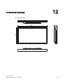
Dimensional drawings.............................................................................................................................. 59
A
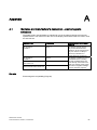
Appendix.................................................................................................................................................. 61
B
A.1
Guidance and manufacturer's declaration – electromagnetic emissions.................................... 61
A.2
Nameplate ................................................................................................................................... 62
A.3
Warranty...................................................................................................................................... 64
A.4
Repairs ........................................................................................................................................ 64
A.5
Environmental protection ............................................................................................................ 64
A.6
Accessory devices ...................................................................................................................... 64
A.7
Trademarks ................................................................................................................................. 65
A.8
Contact ........................................................................................................................................ 65
A.9
China RoHS (Restriction of Hazardous Substances) ................................................................. 66
List of abbreviations................................................................................................................................. 69
Index........................................................................................................................................................ 71
6
RadiForce® LX470W
Instruction Manual, 06/2010, 1015263-001
Introduction
1.1
1
Contents of this document
This document explains the functionality and the approved application of the
RadiForce LX470W 47" Color Flat Panel Display.
To ensure clarity, it does not contain all detailed information on this product.
The contents of this document are neither part of a previous or existing agreement,
commitment or legal relationship, nor does it modify such.
1.2
Additional documentation
Note
These instructions are available on the supplied CD-ROM and on the Internet page of
(http://www.eizo.eu)
SMfit Total Care
Brief instructions for the software "SMfit Total Care".
The context-sensitive help is integrated in the software.
RadiForce® LX470W
Instruction Manual, 06/2010, 1015263-001
7
Introduction
1.2 Additional documentation
8
RadiForce® LX470W
Instruction Manual, 06/2010, 1015263-001
Safety information
2
Please note that LCDs such as the RadiForce® LX470W do not exhibit a zero error rate and
that the image parameters can change over time (e.g. color density or distortion/fading of
colors).
● Please ensure that all necessary steps are taken to avoid violations or incorrect
diagnoses.
● Regular maintenance and calibration are recommended.
In this document, the term "users" refers to medical personnel (e.g. radiology technician,
medical technician), while the term "servicing" implies specifically trained and authorized
personnel (e.g. hospital technician, medical equipment manufacturer).
RadiForce® LX470W
Instruction Manual, 06/2010, 1015263-001
9
Safety information
2.1 General safety notes
2.1
General safety notes
Flawless, safe and reliable operation of the equipment assumes that it has been
professionally transported, stored, mounted and installed as well as careful operator control
and service. The units may only be used for applications for which monitors are normally
used.
For safety reasons, the following precautions must be observed:
DANGER
There is a danger to life if warnings are not obeyed. Severe personal injury or damage to
property may occur. Please observe all warning information present on the display and in
the instruction manual.
Do not open the display
The display may only be opened by trained and qualified personnel. There is risk of an
electric shock.
Components inside the displays are at high voltage. Touching these components is
extremely dangerous!
Servicing and maintenance must be carried out by qualified personnel only.
No liability is accepted for damage to property or injury to persons if the display is opened
by non-qualified personnel.
Never use defective power cables
A damaged power cable may result in fire or electric shock. Only use power cables
approved by the manufacturer.
When disconnecting the power supply cable, always do so by holding the plug. Ensure that
your hands are dry.
Route the cable such that it cannot be tripped over.
Do not insert any objects into the housing
Objects inserted into the housing may result in damage to the unit or personal injury.
Do not place any objects on top of the unit
Liquid entering the unit may result in fire or electric shock.
Connecting
There must be no contact to a patient when handling the connection cables.
Overload
Do not connect too many devices to one socket or extension cable since this could result in
a fire or electric shock.
Observe the information provided by the manufacturer.
10
RadiForce® LX470W
Instruction Manual, 06/2010, 1015263-001
Safety information
2.1 General safety notes
CAUTION
Improper installation may result in extensive damage to property.
Installation must be carried out by specialists.
1. To avoid danger for patients and users, connect your electrical system in accordance
with the safety requirements of EN 60601-1-1 (IEC 60601-1-1) "Safety requirements for
medical electrical systems".
In order to guarantee that the housing discharge current in the event of a first fault does
not exceed 500 µA, the display must be connected to an additional PE connection. The
bracket of the display's support mechanism has its own grounding (PE conductor). This
grounding together with the PE conductor of the display means that the housing
discharge current always remains less than 500 µA, even in the event of a first fault. The
PE conductors of the display and of the separate PC are considered as a first fault
event.
2. Use appropriate measures to ensure that the leakage currents in particular remain
below the necessary limits:
Appropriate measures include:
– Separators for signal input or signal output unit
– Use of a safety isolating transformer
– Use of the additional protective conductor terminal
3. Device and patient must never be touched simultaneously.
4. It must be specifically mentioned that the display is only suitable for a patient
environment, but not for contact with a patient.
5. Only use video cables with BNC connectors and interface cables which are specified by
the manufacturer.
The serial interface cable must have a female Sub-D connector at the computer end.
6. Use power cables with PE contacts. Only plug the device into sockets with protective
grounding.
7. For certain applications, the video ground can be connected separately to the PE via the
additional PE conductor in the connection panel. Observe EN 60601-1-1 (IEC 60601-11).
8. Close the connection panel using the cover provided, and secure with the screws.
9. Note for users:
The closed connection panel may only be opened by trained and qualified personnel.
10.Servicing information:
If housing parts have to be removed for servicing, this must not be carried out in the
presence of the patient or user. Only connect displays with a VESA connection on the
rear panel to the power supply when the VESA plate is screwed on.
11.Important:
Note that displays can fail and that the image properties such as brightness, contrast or
color location can change with time.
Please ensure that all steps are taken to avoid injuries or incorrect diagnoses. Regular
maintenance and calibration must be carried out e.g. with SMfit Total Care. Observe all
regulations of the country in which the display is used.
RadiForce® LX470W
Instruction Manual, 06/2010, 1015263-001
11
Safety information
2.1 General safety notes
CAUTION
Failure to observe warnings may result in substantial damage to property
Ensure sufficient heat dissipation
Ventilation slots are provided on the housing base, the top of the cover, the rear panel and
the side panels. The permissible ambient temperature range (see instruction manual) must
not be violated.
Installation on a desk:
Place the display on a hard, level surface at least 10 cm from the wall and 15 cm away
from other devices.
For ceiling suspension:
Distance from wall at least 10 cm. Several displays can be mounted horizontally or
vertically and directly adjacent to one another.
Avoid sources of heat
Do not install the display in the vicinity of sources of heat, e.g. radiators, heating appliances
or other devices which can generate or emit heat.
Do not subject display to excessive shocks
Take care when transporting! Use the original packaging, and transport correctly oriented!
Be sure to protect the LCD module in particular from shocks.
Care of display / Cleaning agents
The screen surface (front panel) is extremely sensitive to mechanical damage.
Absolutely avoid scratches, shocks etc.
Remove water drops immediately; extended contact with water discolors the surface.
Clean the screen and the housing using only the cleaning agents referred to in the
instruction manual.
12
RadiForce® LX470W
Instruction Manual, 06/2010, 1015263-001
Safety information
2.1 General safety notes
NOTICE
Touching the screen surface can result in brief disturbances to the image
Due to mechanical pressure or electrostatic discharging, touching the screen can result in
brief disturbances to the image.
Only switch on cold displays following their adaptation to room temperature
If the display is brought into a room with a higher or rising temperature, condensation is
formed inside and outside the unit. In such a case, do not switch on the display until the
condensation has evaporated. The display will otherwise be damaged.
What to do if the display is faulty
If the following conditions exist, the display must be disconnected from the power supply
and checked by qualified personnel:
Damage to the plug or power cable.
Following the entry of liquid into the unit.
If the unit has been exposed to moisture.
If the unit does not function or if you cannot eliminate a fault using the instruction
manual.
If the unit has been dropped and/or the housing damaged.
If the unit smells of burning or produces peculiar noises.
Information for installations in the USA and Canada
Molded power supply plugs must comply with the requirements for "hospital grade
attachments" CSA Std. C22.2 No. 21 and UL 498.
Information for installations in China
Only use the the power cables approved for China. These power cables are identified by
the labels "CCC" or "CQC".
See also
Installation site (Page 19)
Distances and arrangement of units (Page 20)
Mounting the device (Page 21)
General connection information (Page 23)
Connector location (Page 24)
Cleaning (Page 51)
Safety regulations (Page 57)
RadiForce® LX470W
Instruction Manual, 06/2010, 1015263-001
13
Safety information
2.2 Product-specific safety notes
2.2
Product-specific safety notes
If the equipment has been designed or, when required, modified for connection to an IT
power distribution system, the equipment installation instructions shall so state.
DANGER
Touching the monitor
A patient and the monitor must not be touched simultaneously by a person or chain of
persons.
CAUTION
1. Do not connect devices which are not part of the medical system.
2. The device must only be opened by trained personnel.
Disconnect the power plug before opening the device.
14
RadiForce® LX470W
Instruction Manual, 06/2010, 1015263-001
3
Description
3.1
Scope of delivery
Note
EIZO recommends that you keep the packaging material for subsequent transport of the
display.
RadiForce® LX470W
2 MP 47" Color Flat Panel Display.
RadiForce® LX470W white
Order No.: 6GF6260-5FA10
RadiForce® LX470W black
Order No.: 6GF6260-5FA11
Additional components in scope of delivery
● CD with user manual and SMfit Total Care
● Power cord for Europe
● Power cord for US
● Power cord for China
● DVI cable
● Remote control
3.2
Applications
The RadiForce® LX470W Color Flat Panel Display has been specially designed for use with
medical imaging. It is envisaged for installation in a ceiling suspension system.
RadiForce® LX470W
Instruction Manual, 06/2010, 1015263-001
15
Description
3.3 Important features
3.3
Important features
Performance features
The display has the following features which permit a wide range of applications:
Large 47" picture diagonal
With a picture diagonal of 47" and a resolution of 1920 x 1080 pixels, the display is suitable
for simultaneous use of several image sources. The display is particularly suitable for
DICOM x-ray images or as a second monitor for surgery or endoscopy.
Perfect picture reproduction thanks to LCD technology
Distortions in the image geometry do not occur with LCD technology.
The flat panel display provides a flicker-free picture even with low refresh rates. The display
thus fulfills even the strictest ergonomic requirements.
The Color Flat Panel Display has a TFT display module with a very wide viewing angle. The
use of state-of-the-art LCD technology allows a high luminance.
Fully Automated Stability
The Color Flat Panel Display is equipped with an automated stability system (Fully
Automated Stability) in accordance with the DICOM standard. The integrated stability system
(ISS) ensures consistent luminance levels using an integral light sensor in the center of the
backlight. Using SMfit Total Care and an external photometer option obtainable from EIZO,
the ISS sensor is automatically adjusted to ensure traceable calibration.
The display is precalibrated in the factory. It is supplied from factory with a total of five
defined look-up tables. The saved calibration data simplify installation and servicing: Even if
the graphics card or workstation is replaced, e.g. during upgrade, the graphics settings are
retained and there is no need to recalibrate the monitor.
Communication interface
The operating states of the display can be read via the communication interface which is
connected via the DVI port: The display can be set to a Power Safe Mode. In particular the
operating capability of the display can be scanned via this interface in critical systems.
Simultaneous display of different image sources
The versatile signal inputs can be used either for a "picture-in-picture" display, or next to
each other with use of the widescreen format.
16
RadiForce® LX470W
Instruction Manual, 06/2010, 1015263-001
Description
3.3 Important features
Settings for optimizing the application
The reproduction properties can be adapted using the SMfit Total Care software tool to
achieve optimum picture display.
The display can be adapted to the local lighting conditions at the click of a mouse using the
five preset practice-oriented look-up tables or automatically calibrated to the desired
luminance levels using the LUT calculation function of the SMfit Total Care software.
RGB input (15-pin Sub-D/DVI/HDMI)
The display is connected to the computer system using either the 15-pin Sub-D connector,
the DVI-I input socket or the HDMI input socket. BNC connections such as RGBS, SoG or
YPbPr can be plugged into the VGA input via adapter cables.
If necessary, the display is adapted using an OSD menu.
Video inputs
The display has additional video inputs such as HD-SDI, S-Video and Composite. The
display can therefore be operated with analog standard video signals (PAL/NTSC/HD). The
RGB and video inputs can be simultaneously connected to different signal sources.
Protective glass
The RadiForce® LX470W has anti-glare protective glass fitted over the top of the LCD panel
to protect the surface of the panel against bumps and scratches. The display is protected at
the front against moisture (IPx4 protection). The space between the protective pane and the
panel is sealed to prevent dust from entering, thus helping ensure the internal surfaces
remain clean.
RadiForce® LX470W
Instruction Manual, 06/2010, 1015263-001
17
Description
3.3 Important features
18
RadiForce® LX470W
Instruction Manual, 06/2010, 1015263-001
Application planning
4.1
4
Installation site
Provide adequate ventilation
Ventilation holes are located on the rear of the housing. These ventilation holes must not be
covered or closed, since otherwise the heat generated in the device cannot be dissipated
sufficiently.
Avoid dusty environments
The display has been designed for use in the clean environment of medical diagnostics. The
display dissipates heat through the openings at the rear. Dust from dirty environments can
penetrate into the display through these openings. In the extreme case, deposits are
possible which become evident as dark spots in a white picture and which can result in
deterioration of the luminance. Protect the display from dust, e.g. during building measures
at the installation location, and use the original packaging or service packaging for transport.
Observe the permissible ambient temperature range
The unit must not be operated outside the permissible ambient temperature range.
Avoid reflections on the screen
The display has an anti-glare surface which is only effective with a clean, grease-free
screen.
The display is equipped with a protective glass pane with a non-reflective optical coating on
both sides and is particularly suitable for use in sterile environments when cleaning agents
are used.
If the screen surface is dirty, clean it using a suitable microfiber cloth.
Please note the additional cleaning instructions, see the section "Service and Maintenance"
(Page 51).
● Position the display so that reflections of lights, windows, furniture with shiny surfaces or
light-colored walls do not appear on the screen.
In order to reduce mirroring on the unit, only use non-dazzling reflector lights for the ceiling
lighting.
RadiForce® LX470W
Instruction Manual, 06/2010, 1015263-001
19
Application planning
4.2 Distances and arrangement of units
Change of environment
If the unit is brought into a warm environment from a cold one, condensation may form in the
unit. The unit should not be switched on until all the condensed water has evaporated,
including that inside the unit. This may take several hours, depending on the conditions.
See also
General safety notes (Page 10)
Cleaning (Page 51)
4.2
Distances and arrangement of units
Minimum distances from other devices and a wall
The display has a VESA-400x200 installation connection. The display should be positioned
at least 10 cm at the side and rear from a wall, or 15 cm from other equipment.
The display, especially the panel surface, is sensitive to shock. An impact on the panel
surface can lead to total failure. Avoid such mechanical influences at all costs.
If the display is installed to be movable
make sure that the moved mass does not endanger persons or fittings.
See also
General safety notes (Page 10)
20
RadiForce® LX470W
Instruction Manual, 06/2010, 1015263-001
5
Mounting
5.1
Mounting the device
Taking the device out of the packaging
CAUTION
The device must be removed from the packaging and carried by at least 2 persons.
Wear appropriate protection to prevent injuries should the device be dropped.
1. Open the packaging carefully and remove from the display.
Make sure that the display cannot tip over.
2. Hold the device at the bottom and side, and remove from the packaging.
Mounting the device
The display has a VESA adapter/400 x 200 mm.
Since the screws are of particular importance for the installation, observe the following:
Fastening screw specifications
Number
4
Thread
M8
Strength
8.8 in accordance with ISO 898-1
Insertion depth
10 mm (minimum) / 12 mm (maximum)
Tightening torque
Max. 10 Nm
● Make sure when installing the display that the adapter is designed for 4-fold safety
(monitor mass is approx. 40 kg).
● An installed stand must be sufficiently stable such that tilting (up to 10°) does not result in
toppling of the device.
● Mounting units, e.g. a stand or wall bracket, must be tested and approved by the
manufacturer for the weight to be supported. It is therefore advisable to use the display
manufacturer's mounting units since these satisfy the required demands.
See also
General safety notes (Page 10)
RadiForce® LX470W
Instruction Manual, 06/2010, 1015263-001
21
Mounting
5.1 Mounting the device
22
RadiForce® LX470W
Instruction Manual, 06/2010, 1015263-001
6
Connection
6.1
General connection information
CAUTION
All information and warnings related to this product must be observed to ensure dangerfree operation.
CAUTION
Observe shielding measures
The shielding measures described in the applicable national EMC guideline must be
observed. If these guidelines are not observed, malfunctioning of the display may result.
Observe the grounding measures
To ensure that the permissible leakage current is not exceeded in the case of a fault, you
must additionally ground the monitor with a separate ground line.
Information on cable installation
Only shielded cables are permitted for all signal connections.
If the relevant facility is available on the connector, all plug connections must be
screwed tight or locked.
If signal and power supply cables are routed next to one another, reversible pixel errors
may occur if there is high interference on the power supply network.
The display must not share a power supply with motors or valves (interference!).
Externally connected cables can represent a trip hazard. Make sure that all incoming
cables are safely routed.
Cable grips are provided in the device. Use these to secure the cables against
unintentional loosening.
See also
General safety notes (Page 10)
Electromagnetic compatibility (Page 58)
RadiForce® LX470W
Instruction Manual, 06/2010, 1015263-001
23
Connection
6.2 Connector location
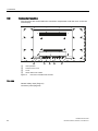
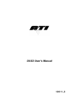
6.2
Connector location
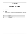
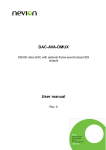
The connectors are located within the connection compartment under the cover on the rear
of the display.
1
①
②
③
④
2
3
4
2
OSD operation
Screws for the cover
Cover
Strain relief for the cables
Figure 6-1
Rear view of RadiForce® LX470W
See also
General safety notes (Page 10)
Connector panel (Page 25)
24
RadiForce® LX470W
Instruction Manual, 06/2010, 1015263-001
Connection
6.3 Connector panel
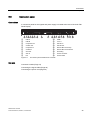
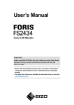
6.3
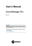
Connector panel
Connections
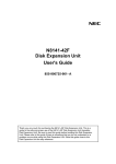
A connection panel for the signals and power supply is located at the rear of the Color Flat
Panel Display.
①
②
③
④
⑤
⑥
⑦
⑧
⑨
USB-A
USB-B
Composite Out
S-Video Out
Composite In
S-Video In
VGA Out
VGA In
DVI
Figure 6-2
⑩
⑪
⑫
⑬
⑭
⑮
⑯
⑰
⑱
HDMI
5 V/1 A
HD-SDI In
HD-SDI Out
RS 232 Bus Service/Up
RS 232 Bus Service/Down
Grounding
Power connector
Power switch
Connection panel of RadiForce® LX470W
See also
Connector location (Page 24)
Connecting the signal cables (Page 26)
Connecting the power cord (Page 28)
RadiForce® LX470W
Instruction Manual, 06/2010, 1015263-001
25
Connection
6.4 Connecting the signal cables
6.4
Connecting the signal cables
CAUTION
When installing the cable, avoid danger of tripping
Route the cable such that it cannot be tripped over.
CAUTION
Use identical cable lengths for R, G and B signals
When connecting to the RGB analog sockets, the three cables for the R, G and B signals
must be of equal length. Otherwise, color fringing, which appears similar to convergence
faults, will occur due to unequal propagation times.
Note
Names of the image signals
The image signals coming from a graphics card are referred to below as RGB signals, and
those coming from a camera, DVD player, video recorder etc. as video signals.
In the OSD menu, some of the menu displays are also appropriately identified by RGB or
video in the header.
The signal connections are located at the rear of the flat panel display.
● You may connect all signal inputs simultaneously.
15-pin Sub-D socket
Various signals can be connected to the 15-pin Sub-D socket with or without an adapter:
● VGA cable with 15-pin Sub-D connector (male) for the analog input to the 15-contact
Sub-D connector (female).
● 5x BNC cable (RGBS, RGB and H+V Separate Sync), with the 5x BNC to VGA adapter.
● 4x BNC cable (RGB and H+V Composite Sync), with the 5x BNC to VGA adapter.
● 3x BNC cable (G and H+V Separate Sync), with the 5x BNC to VGA adapter.
● 2x BNC cable (G and H+V Composite Sync), with the 5x BNC to VGA adapter.
● 1x BNC cable (SoG, Sync on Green), with the BNC to VGA adapter.
● YPbPr (Component Video), with the 5x BNC to VGA adapter.
26
RadiForce® LX470W
Instruction Manual, 06/2010, 1015263-001
Connection
6.4 Connecting the signal cables
DVI socket
The DVI cable can be connected in two manners:
● Connect the DVI cable with DVI digital signal or DVI analog signal.
HDMI socket
Two types of cable can be connected to the HDMI socket:
● HDMI cable
● DVI cable (digital mode) with a DVI to HDMI adapter or cable
HD-SDI socket (BNC)
● Connect the video cable for the HD-SDI input to the BNC socket.
4-pin mini-DIN socket (video input)
● Connect the video cable for the sync video input (Y/C signal) to the 4-pole mini-DIN
socket.
Composite BNC socket (video input)
● Connect the video cable for the Composite input to the BNC socket.
See also
Connector panel (Page 25)
RadiForce® LX470W
Instruction Manual, 06/2010, 1015263-001
27
Connection
6.5 Connecting the power cord
6.5
Connecting the power cord
The power supply socket is on the rear of the flat panel display (only open using appropriate
tool!). The display power supply is connected using an appliance plug.
● Insert the appliance plug of the supplied power cord into the mains socket.
● The power cord can be secured using a cable grip.
3RZHUVZLWFK
3RZHUVXSSO\FRQQHFWLRQ
WARNING
Only use the supplied power cord, or a cable with PE conductor and appliance plug
to DIN 49 547, IEC 320 (max. length 3 m). Furthermore, the cable must adhere to all
local safety regulations applicable to the specific country in which the display is used.
Device fuses must only be replaced by the repair centers or servicing department.
Note for North America: Molded power supply plugs must comply with the
requirements for hospitals with respect to CSA Std. C22.2 No. 21 and UL 498.
See also
Connector panel (Page 25)
Power supply (Page 53)
28
RadiForce® LX470W
Instruction Manual, 06/2010, 1015263-001
7
Commissioning
7.1
Switching on the unit
● Switch the device on using the power switch.
The EIZO logo is displayed for a short time.
● If no signal is present, a black image is output on the display.
● If a signal is present, the black image disappears.
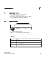
7.2
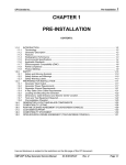
Operator controls
①, ②, ③, ④: OSD operation (4 keys)
Figure 7-1
Rear view of RadiForce® LX470W: OSD operation
The four keys are located at the rear in the bottom right-hand corner of the display.
Key functions
In the OSD menu, the keys have the following functions:
Key
Action
1
Open OSD menu
Toggle
2
Navigate between submenu/tab
Decrease/change value
3
Navigate between submenu/tab
Increase/change value
4
Leave OSD or submenu (settings are retained)
RadiForce® LX470W
Instruction Manual, 06/2010, 1015263-001
29
Commissioning
7.3 Description of OSD menu
7.3
Description of OSD menu
7.3.1
OSD overview
The OSD menu is used to make settings for operation of the flat panel display with a source.
The OSD can also be operated without an input signal to a limited extent.
7.3.2
Menu functions
Program levels
Printed/identified in bold type
Menu title (main menu or first submenu)
Main menu
Function
Adjustment/range
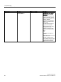
Description
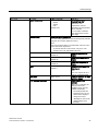
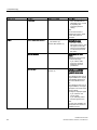
Picture quality
Brightness
Slider control
Set brightness
Default: 50
Adapting the representation
of darker picture areas.
Note
The brightness settings are
already optimized for digital
DVI signals.
Do not change the values
manually, as this can
result in an impairment of
picture quality (loss of
gray scales).
Contrast
Slider control
Set contrast
Default: 50
Adapting the representation
of brighter picture areas.
Note
The contrast settings are
already optimized for digital
DVI signals.
Do not change the values
manually, as this can
result in an impairment of
picture quality (loss of
gray scales).
Backlight
Slider control
Default: Max. 50 %
30
Adjust brightness of display
backlight
Adjustment of overall
brightness to ambient
lighting.
RadiForce® LX470W
Instruction Manual, 06/2010, 1015263-001
Commissioning
7.3 Description of OSD menu
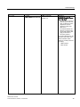
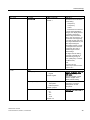
Main menu
Function
Adjustment/range
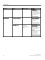
Color temperature
Native
9300°K
7300°K
User
Default: User
Description
Set the desired color
temperature or hue
Three fixed color
temperatures and one
adjustable color temperature
can be selected.
You can define a different
color temperature for each
video input.
Set user color
Define user color temperature
The color setting defined here can be subsequently selected
using the color function (selection "User").
Note
If the color location setting is corrected with "Set user color",
some color levels may be lost.
To prevent the loss of color levels, carry out a color
correction via "LUT" with SMfit Total Care.
→Red
Slider control
Default: 50
→Green
Slider control
Default: 50
→ Blue
Slider control
Default: 50
Hue
Slider control
Default: 0
Select red component of
display
Select green component of
display
Select blue component of
display
Setting of hue for RGB and
video signals
Note
"Hue" can only be set for SVideo or Composite signal.
Saturation
Slider control
Setting of saturation for RGB
and video signals
LUT backlight command
On / Off
Allows access to the
backlight
When "On" is selected, the
settings made in the
"Backlight" menu are only
available temporarily:
The settings made are
rejected as soon as you
switch off the display or
change the source.
"Backlight" is reset to the
default setting of the
firmware.
RadiForce® LX470W
Instruction Manual, 06/2010, 1015263-001
31
Commissioning
7.3 Description of OSD menu
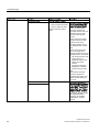
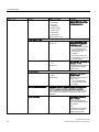
Main menu
Function
Adjustment/range
Description
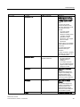
LUT
Default: LUT1
Selection of LUT
(Look Up Table)
An LUT changes the gamma
curve of the display. By
selecting a different LUT you
can, for example, emphasize
certain gray scales.
Note
Select a DICOM LUT for
viewing x-ray images.
Image adjustment
Perform auto adjustment…
Execute
Execution of autofunction
"Position", "Phase" and
"Frequency" are set
automatically.
Note
"Perform auto adjustment"
can only be used with the
analog signal inputs.
Image size / zoom
1:1
Fill screen
Fill to aspect ratio
Default: 1:1
Selection between different
image size settings:
1:1:
The picture is displayed on
screen with its original
resolution.
Fill screen:
The picture is displayed to fill
the complete screen
(1920 x 1080 pixels).
Fill to aspect ratio:
The picture is zoomed to the
maximum screen area with
retention of the aspect ratio.
32
RadiForce® LX470W
Instruction Manual, 06/2010, 1015263-001
Commissioning
7.3 Description of OSD menu
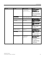
Main menu
Function
Adjustment/range
Description
Sharpness filter
Slider control
Sharpness setting can be
selected in order to reduce
scaling artifacts or to make
the image appear "softer"
Note
You can only use the
"Sharpness filter"function
when the "Sharpness mode"
menu has been set to
"Normal".
You must visually
determine which
sharpness setting is best.
A smaller value will
generate a "softer"
impression, and a higher
value a "harder"
impression.
Common filters are available
for the RGB picture sources
(VGA, DVI).
The interpolation filters
depend on the input
resolution.
At lower resolutions, the filter
calculates the value for the
non-controlled pixels.
Sharpness mode
Enhanced / Normal
Default: Enhanced
H-Position
Slider control
If you select "Enhanced",
the picture with the
sharpest setting is
displayed.
If you select "Normal",
you can make the picture
appear "softer" using the
sharpness control.
Shift picture in horizontal
direction
With identical display and
graphics card settings, the
complete picture to be
displayed fills the display
area of the monitor with the
exact number of pixels.
V-Position
Slider control
Shift picture in vertical
direction
With identical display and
graphics card settings, the
complete picture to be
displayed fills the display
area of the monitor with the
exact number of pixels.
Phase
RadiForce® LX470W
Instruction Manual, 06/2010, 1015263-001
Slider control
Setting the frequency and
33
Commissioning
7.3 Description of OSD menu
Main menu
Function
Adjustment/range
Frequency
Slider control
Description
phase of the input signal
If the vertical lines are
still slightly fuzzy, correct
by adjusting the
"Frequency/Phase"
setting.
Note
We recommend that a
vertical line from the "Pixel
On/Off" test pattern is
displayed.
Signal
Active adjustment window
Main window (1)
PiP window (2)
Default: Main window (1)
Source selection
Select
Selecting the active
adjustment window
The menu "Active
adjustment window" does
not appear in the OSD
until you have switched
on "Picture layout PaP,
PiP, PoP".
Select source for main
display
Selection of picture source
for full format image.
If you call this OSD
menu, the currently
displayed source is
preselected.
Source scan
On / Off
Default: On
If no signal is displayed:
Activate/deactivate the
automatic source scan
On:
If the displayed source is no
longer available, the display
automatically searches for
the next available source.
Off:
If the displayed source is no
longer available, no image is
displayed: The screen of the
display is black.
An image is displayed again:
If you switch on the
source again.
If you manually select
another signal source.
Note
If no signal is available, the
display does not search for
available sources.
34
RadiForce® LX470W
Instruction Manual, 06/2010, 1015263-001
Commissioning
7.3 Description of OSD menu
Main menu
Function
Adjustment/range
Picture layout PaP, PiP, PoP On / Off
Default: Off
Description
Switching on or off the
preconfigured picture layout
(PaP; PiP; PoP)
1. As soon as you switch on
"Picture layout PaP, PiP,
PoP", a selection "Active
adjustment window"
appears in each OSD
Main menu.
2. You define whether the
settings you have made
for the OSD window also
apply to the main or
secondary window.
The number displayed on the
right-hand side of the OSD
window indicates which
window is currently active for
the setting:
1: Main window
2: PiP window
RadiForce® LX470W
Instruction Manual, 06/2010, 1015263-001
35
Commissioning
7.3 Description of OSD menu
Main menu
Function
Adjustment/range
Description
Set picture layout
Setting the picture layout
→ Layout format
Picture in picture (PiP)
Picture and picture (PaP)
Picture off picture (PoP)
Default: Picture in picture
(PiP)
The following picture layouts
can be selected using the
menu "Set picture layout":
Picture in picture (PiP):
The image content of a
secondary window source is
displayed over the main
picture (≙ main window
source).
Picture and picture (PaP):
Two pictures from a main
window source and a
secondary window source
are displayed next to each
other.
Picture off picture (PoP):
Up to five images from
different window sources are
displayed next to each other.
The image from the main
window source is
displayed larger on the
bottom side of the
window.
The other images are
displayed in a smaller
format on the top side.
Note
With "Picture off picture
(PoP)" the images are
displayed with a delay. You
cannot use this setting for
live mode.
→ Main window source
→ Secondary window source
Selection of the window
sources which are displayed
in the respective "Picture in
picture (PiP)", "Picture and
picture (PaP)" and "Picture
off picture (PoP)" windows
See Section "Enable picture
layout (PiP/PaP/PoP)
(Page 42)" for possible
combinations of signal
sources.
36
RadiForce® LX470W
Instruction Manual, 06/2010, 1015263-001
Commissioning
7.3 Description of OSD menu
Main menu
Function
Adjustment/range
→ Synchronization window
Main window (1)
PiP window (2)
Default: Main window (1)
Description
Set which of the main or
secondary windows is
selected as the
synchronization window
Note
The menu "Synchronization
window" can only be used if
the "Picture in picture (PiP)
setting is active.
PiP adjustments
The menu "PiP adjustments" can only be used if the "Picture
in picture (PiP) setting is active.
→ PiP size
Selection of "Picture in
picture (PiP)" window size
→ H-Position
Slider control
Setting of horizontal position
of "Picture in picture (PiP)"
window
→ V-Position
Slider control
Setting of vertical position of
"Picture in picture (PiP)"
window
→ Transparency
Slider control
Selection of "Picture in
picture (PiP)" window
background ("Opaque" or
"Transparent").
Saturation adjustment
On / Off
Activates the color setting of
the "Saturation" in the
Picture quality main menu
Default: Off
Deinterlacing
Select
Setting of "Deinterlacing"
method
If an interlaced signal is
present, you can select the
"Deinterlacing" method.
Color / Monochrome
Color
Monochrome
Default: Color
RadiForce® LX470W
Instruction Manual, 06/2010, 1015263-001
Switching over of signal
between black-and-white
and color modes
If a monochrome signal is
present, it appears green on
the color display.
To obtain correct b/w
images, set the signal
parameter to
"Monochrome".
37
Commissioning
7.3 Description of OSD menu
Main menu
Function
Adjustment/range
Description
ADC calibration...
Execute
Automatically calibrate A/D
converter for the applied
video level
The video level range of the
system is checked, and the
display set accordingly. This
results in optimum
adjustment of the individual
RGB A/D converters to the
video source.
The calibration results in a
larger and more flexible
video level range (e.g., the
full brightness is also
achieved at 700 mV if the
video level is limited at this
value).
Note
A particular test pattern is
required!
Please follow the instructions
in the OSD menu.
The A/D converters have
already been factory-set and
it is not usually necessary to
readjust them in the field.
38
RadiForce® LX470W
Instruction Manual, 06/2010, 1015263-001
Commissioning
7.3 Description of OSD menu
Main menu
Function
Switch loop
Adjustment/range
Description
Slider control
The following four
parameters are of relevance
to this setting:
H frequency
V frequency
V total
Interlaced/non-Interlaced
Default: 1
If one of these parameters
changes, the display treats it
as a timing change and
initiates resynchronization
via an "Auto in progress". To
prevent this from happening
as a result of each and every
minor signal disturbance, the
value representing the
permissible number of faulty
or changed frames must be
increased in the case of
unstable signal sources.
Disadvantage
The higher the tab setting,
the longer it will take for a
desired timing change to
occur (delayed by a number
of milliseconds).
Note
You can only use
Switch loop if "Source scan"
is set to "On".
Utilities
OSD
→ Language
German
English
Default: English
→ Transparency
Opaque
Transparent
Half transparent
Default: Opaque
→ OSD time out
Off
5s
10 s
30 s
1 min
Use the "Language" menu to
select the language of the
OSD menu
German or English can be
selected. English is the
delivery default setting.
Selection of OSD
background: "Opaque",
"Transparent" or Half
transparent.
Close the OSD menu after a
defined time
Default: Off
RadiForce® LX470W
Instruction Manual, 06/2010, 1015263-001
39
Commissioning
7.3 Description of OSD menu
Main menu
Function
Adjustment/range
→ Position
Up left
Up middle
Up right
Middle left
Middle middle
Middle right
Bottom left
Bottom right
Description
Setting of position of OSD
menu on screen from eight
predefined positions
Default: Bottom right
Power Save / DPMS
→ DPMS
On / Off
Default: On
The DPMS(Display Power
Management-System) can
be switched on/off
The backlight is switched
off or darkened if you
activate "DPMS" but an
input signal is not
available.
This saves power, and
increases the service life
of the backlight.
→ Backlight
Dimmed
Off
The "Backlight" can be set to
"Dimmed" or "Off"
Default: Off
The Backlight is switched off
or darkened if the DPMS
modeis active.
Communication
→ Communication interface
DDC
USB
Default: DDC
Source selection sequence
Selection of interface for
communication
The serial communication is
always active.
You can additionally
choose between USB
and DDC.
The Source selection sequence defines the sequence in
which the sources are to be automatically searched
Source selection is interrupted as soon as the first source
with an active video signal has been found. This is then
displayed.
Reset operations
Reset display settings to
factory defaults
The display settings are
reset to the default setting of
the firmware.
Note
All parameters are deleted
and reset to the default
setting of the firmware.
40
RadiForce® LX470W
Instruction Manual, 06/2010, 1015263-001
Commissioning
7.3 Description of OSD menu
Main menu
Function
Info
7.3.3
Adjustment/range
Description
Information
Current display settings and
status information can be
retrieved here in the
respective picture mode.
Serial number
Temperature [°C]
Power on time [h:m]
Backlight on time [h:m]
Backlight on above
350 cd/m² [h]
Source
Mode
Source timing
2nd source
Mode
2nd source timing
FW type
FW version
OSD version
Config version
SDK version
Lock/unlock OSD menu
CAUTION
Locking/unlocking of the OSD is only permissible for authorized servicing personnel. The
OSD must be locked if a faulty operation on the part of the user could have a detrimental
effect on the approved application of the display.
Lock
You can lock the call from the OSD if the OSD is not active.
To lock, enter the following key combination without interruption:
● Press button "4" once and then button "2" three times in quick succession.
The OSD menu is locked.
Cancel locking
● Press button "4" once and then button "2" three times (if the OSD is not active).
Locking of the OSD menu has been canceled.
Delivery state
The OSD is unlocked.
RadiForce® LX470W
Instruction Manual, 06/2010, 1015263-001
41
Commissioning
7.3 Description of OSD menu
7.3.4
Picture layout (PaP/PiP/PoP)
PaP: Picture and picture
"Picture and picture" layout; two images from main and secondary window sources are
displayed next to each other.
PiP: Picture in picture
"Picture in picture" layout; the image content of a secondary window source is displayed over
the main picture (≙ main window source).
PoP: Picture on picture
"Picture on picture"Picture on picture" layout; up to five images from different window
sources are displayed next to each other.
● The image from the main window source is displayed larger on the bottom side of the
window.
● The other images are displayed in a smaller format on the top side.
Selection of picture sources
The main picture can be selected. The four other picture sources are automatically added in
accordance with the table "Picture source combination".
NOTICE
Live images must not be displayed in PoP mode
With "Picture off picture (PoP)" the images are displayed with a delay. You cannot use this
setting for live mode.
42
RadiForce® LX470W
Instruction Manual, 06/2010, 1015263-001
Commissioning
7.3 Description of OSD menu
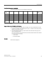
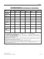
Possible window source combination
The following window sources can be displayed simultaneously:
PiP / PaP
DVI digital
DVI analog
HDMI
VGA
S-Video
HD-SDI
Composite
Video
(CVBS)/SoG
DVI digital
-
-
+
-
+
+
+
DVI analog
-
-
+
-
+
+
+
HDMI
+
+
-
+
-
-
-
VGA
-
-
+
-
+
+
+
S-Video
+
+
-
+
-
-
-
HD-SDI
+
+
-
+
-
-
-
Composite
Video
(CVBS)/SoG
+
+
-
+
-
-
-
Possible
combinations
Picture source combination
Image settings on the PiP/PaP or PoP window
You can individually set the image display and quality of the various PiP/PaP/PoP windows.
1. As soon as you switch on the "Enable Picture Layout ", a selection "Active setup window"
appears in each OSD main menu.
2. You define whether the settings you have made for the OSD window also apply to the
main or secondary window.
The number displayed on the right-hand side of the OSD window indicates which window
is currently active for the setting:
– 1: Main window
– 2: Secondary window
See also
Menu functions (Page 30)
RadiForce® LX470W
Instruction Manual, 06/2010, 1015263-001
43
Commissioning
7.4 Implementing settings
7.4
Implementing settings
7.4.1
Avoidance of image sticking
● Use a screen saver function in order to reduce "image sticking" that may occur with TFT
displays.
● If the device is no longer required: Switch off the device.
● If the application permits a power saving mode, the device can be switched to this status:
Set the option in your application for switching the device to power saving mode.
Image sticking
Image sticking is an effect in which a faint image of the previous screen contents can be
seen after the display contents have changed. By using a screen saver with continuously
changing screen contents, an unnecessary long depiction of a single image on the screen
can be avoided.
7.4.2
Adjusting the image geometry
The display automatically recognizes the applied standard, and set-up values for each
standard are preprogrammed. However, depending on the graphics card used, it may still be
necessary to align and size the picture for the selected standard.
7.4.3
Adaptation of display – video source / graphics card
As with all monitors, the Flat Panel Display also has certain limits, e.g. maximum resolution
and refresh rate.
● Set the graphics card when using the display such that the limits are observed.
Requirement
CAUTION
Exact setting only possible with photometer
Exact setting of the brightness and contrast is only possible with a photometer:
Serial Spot Meter
Serial Luminance Meter
Universal Serial Luminance Meter
Advanced Serial Luminance Meter
44
RadiForce® LX470W
Instruction Manual, 06/2010, 1015263-001
Commissioning
7.4 Implementing settings
CAUTION
Fine adjustment of analog inputs: only via 15-pin Sub-D and DVI-I sockets
Fine adjustment of digital input: Unnecessary
Carry out the fine adjustment of the flat panel display only via the two analog ports (15pin Sub-D and DVI-I sockets).
The digital input (DVI-D) does not require a fine adjustment of brightness and contrast
since the signal display is always optimum. With a fine adjustment, it is possible that
gray scales are not displayed.
RGB sources (via 15-pin Sub-D or DVI-I connector) supply analog signals which are
basically intended for conventional CRT monitors and which are processed directly by them.
In contrast, the analog signals must be converted for the Flat Panel Display into digital
signals by a video digitizer. Depending on the source, cable length and video mode (e.g.
VGA, SVGA, XGA), this conversion may cause certain deviations which cannot be corrected
fully automatically by the Flat Panel Display.
● You must carry out a manual fine adjustment to achieve optimum picture display with an
analog input signal (VGA/DVI-I). By means of this manual fine adjustment, you match the
flat panel display (or more exactly the video digitizer) to the respective video source.
In order to optimize the display settings for the installed graphics card and guarantee that all
grayscales can be distinguished, we recommend that brightness and contrast are adjusted
only for the analog inputs.
Configure display for optimum performance with the installed graphics card
Note that the calibration in the look-up table must not be affected by these settings.
EIZO GmbH displays are calibrated in the factory and retain the settings:
1. To reduce the brightness using the OSD control elements, use a picture with 0% gray
value (black) and a suitable measuring instrument (we recommend the Serial Spot
Meter).
Reduce the brightness until the measuring instrument displays constant values: The
measured value no longer changes.
Then increase the brightness slightly until the display is just above the lowest black level
(one step is generally sufficient).
2. To set the white value, use a test pattern with 100% gray value (white) and the measuring
instrument.
To ensure that the black value remains unchanged, only adjust the contrast.
3. Increase the contrast until the measuring instrument no longer registers an increase in
light density.
Subsequently reduce the setting of the contrast controller again by 1 to 2 steps until the
measured brightness is slightly below the maximum value.
4. Make sure once again that the black value has not changed.
The black value may change if the contrast has been corrected by a large amount. In this
case, repeat the previously mentioned steps.
RadiForce® LX470W
Instruction Manual, 06/2010, 1015263-001
45
Commissioning
7.4 Implementing settings
Result
The display is now configured for optimum performance with the installed graphics card. If
you are still not satisfied with the light density, you can increase the black and white values
further by adjusting the backlighting in the OSD menu.
CAUTION
A permanently higher setting for the backlighting may reduce the brightness performance
Please note that a permanently higher setting for the backlighting results in a more rapid
reduction in the service life.
Fast adjustment without measuring instrument
Exact adjustment is only possible with a measuring instrument.
If a measuring instrument for the fine adjustment is not available, proceed as follows:
1. Use the SMPTE test pattern.
2. Adjust the brightness so that image sections with 5% and 0% gray value still visibly
contrast.
3. Adjust the contrast so that image sections with 95% and 100% gray value still visibly
contrast. To adapt the luminosity to the ambient lighting, adjust the backlight brightness
(note: factory-set brightness is no longer observed).
7.4.4
Power management
Power management settings
Observe the instructions of the operating system manufacturer regarding the power
management settings. The display supports the so-called DVI DMPM mode (Digital Monitor
Power Management) which can be applied to save energy.
By means of DVI DMPM, the display can be switched off automatically, e.g. after 20 minutes.
7.4.5
Check for pixel defects
Pixel defects (small bright or dark dots) can occur in LCD monitors. During the
manufacturing process, all displays are checked for the permitted number of defective pixels.
During start-up you can check the display e.g. using SMfit Total Care as follows:
● Generate a black test screen and examine the screen for luminous pixel errors.
● Generate a white test screen and examine the screen for non-luminous pixel errors.
Pixel defects on an LCD monitor can not be corrected.
46
RadiForce® LX470W
Instruction Manual, 06/2010, 1015263-001
Software description
8.1
8
Program for changing the display settings
Note
The RadiForce® LX470W display features a latest generation controller module and is
supported by the SMfit Total Care calibration and quality control software.
SMfit Total Care
The SMfit Total Care program is supplied on the enclosed software and documentation CD.
The software is also available as a free download on the EIZO Display Technologies
website.
Used in conjunction with EIZO photometers, SMfit Total Care is a powerful calibration
software tool. The software includes extensive options for adjusting and verifying an LC
display.
The software and documentation CD contains SMfit Total Care documentation. Additional
information is available in a Readme.txt file on the installation CD.
See also
http://www.eizo.eu
http://www.radiforce.com
RadiForce® LX470W
Instruction Manual, 06/2010, 1015263-001
47
Software description
8.1 Program for changing the display settings
48
RadiForce® LX470W
Instruction Manual, 06/2010, 1015263-001
9
Operate
9.1
Note for users
CAUTION
Settings must not be changed by users
None of the settings may be changed on site by the user. This also applies to settings
made using the display keys. These are therefore locked for certain applications. If settings
have to be changed, please contact the responsible servicing department.
If keyboard is locked, contact Service department
If the keyboard is locked, contact the service department in order to unlock it. If you unlock
it yourself, the warranty will no longer be valid!
9.2
Switching on the display
Once installed, operating the display consists mainly of switching the power on and off.
● Switch the device on using the power switch.
RadiForce® LX470W
Instruction Manual, 06/2010, 1015263-001
49
Operate
9.2 Switching on the display
50
RadiForce® LX470W
Instruction Manual, 06/2010, 1015263-001
10
Service and maintenance
10.1
Cleaning
CAUTION
Device maintenance, cleaning and disinfecting
The front panel is extremely sensitive to mechanical damage. Avoid all scratches,
knocks etc.!
Remove drops of liquid immediately; contact with liquids over a longer period can cause
discoloration or allow calcium deposits to form on the surface.
Clean the front panel when dirty using a microfiber cloth and, if necessary, a
recommended cleaning agent. Only clean housing parts using the recommended
cleaning agents.
The entire display must only be disinfected using the tested disinfecting agents.
If cleaning agents are sprayed directly onto the display surface, use a microfiber cloth to
catch drops which run down before they reach the edge of the panel.
Recommended cleaning agents and disinfectants for the monitor:
Agent class
Tested cleaning and disinfection Further examples
agents:
Alcohol
Ethyl alcohol, 96 %
Hospiset cloth
Mikrozid liquid
Aldehyde
Melsitt
Aldasan 2000
Cidex
Kohsolin
Gigasept FF
Chlorine derivatives
Terralin
Disinfecting agents
Morning Mist
Guanidine derivatives
Lysoformin
Quaternary compounds
Incidur spray, undiluted
Standard household washing-up Tempo
liquid
Pyridine derivatives
Activ spray, undiluted
Water
Tap water
Quartamon Med
Fairy Ultra, Pril, Palmolive
Distilled water
Note
Information on cleaning or disinfection of other system components can be obtained from the
respective instructions for use.
RadiForce® LX470W
Instruction Manual, 06/2010, 1015263-001
51
Service and maintenance
10.2 Maintenance
10.2
Maintenance
Routinely check the display settings
The display requires little maintenance. The illumination properties may change slowly due
to aging of the LCD unit and the backlight. For this reason, periodically check and, if
necessary, correct the display settings to ensure compliance with local guidelines. EIZO also
recommends checking the displays for pixel errors.
Measuring instruments
The following devices can be used as measuring instruments:
● Serial Spot Meter
● Universal Serial Luminance Meter
● Advanced Serial Luminance Meter
These photometers can be connected directly to the display.
Carry out quality tests automatically
One can automatically perform all quality tests using the SMfit Total Care program.
Verify and calibrate display properties
The photometers can be used to verify and, if necessary, calibrate the display properties.
Manual modification of settings
One can also manually adjust display settings using a Serial Spot Meter and the
SMfit Total Care program.
NOTICE
Confirm image quality visually after calibrating the display
After calibration, the display must be visually inspected to verify successful and correct
completion of the calibration procedure. This inspection can be performed by reviewing the
SMPTE image. The gray levels should be displayed correctly and visibly at both 5 % and
95 %. Alternatively, the VerLum image can serve as a useful test pattern. Successful
calibration can be verified if the small squares are displayed correctly in all gray shades.
See also
Check for pixel defects (Page 46)
Program for changing the display settings (Page 47)
52
RadiForce® LX470W
Instruction Manual, 06/2010, 1015263-001
11
Technical specifications
Applicability of technical specifications
All technical specifications are valid after a warming-up period of 30 minutes.
11.1
11.2
Display features
Type
Color, TFT, S-IPS
Image Size
1039.7 mm x 584.8 mm
Screen diagonal
47" (119.3 cm)
Resolution
1920 x 1080
Refresh rate
60 Hz
Pixel arrangement
24 bit (3 x 8 bit): 3 subpixels per pixel
Pixel spacing
0.5415 mm x 0.5415 mm
Contrast ratio
Typically 1000:1
Horizontal viewing angle
178° typical
Vertical viewing angle
At least 178°
Response time (gray to gray)
6.5 ms
Backlighting
32 CCFL
Screen brightness
Typically 700 cd/m²
Lifetime of backlight
Typically 50 000 hours (at operating temperature
of 25 °C)
Power supply
Power connector
Non-heating appliance socket
Line voltage
90 to 264 V AC
Line frequency
47 ... 63 Hz
Current consumption
Max. 2.7 A ... max. 1.1 A
Energy consumption
Max. 270 W
Energy-saving mode
DVI DMPM
RadiForce® LX470W
Instruction Manual, 06/2010, 1015263-001
53
Technical specifications
11.3 Electronics
11.3
Electronics
Multi-standard technology
Video modes with resolutions less than 1920 x
1024 can be expanded to the TFT resolution, and
thus utilize the full display area (like multi-sync
CRTs)
Interpolation artifacts must be expected when
displaying images with a resolution other than
1920 x 1024.
Caution
If the timing is frame-buffered or framesynchronized, parts of the picture information
may be lost; the grayscales - the hue for color
images - are also reduced and may be visible).
Timing recognition
11.4
H frequency, V frequency, interlaced, number of
horizontal lines
Inputs/Outputs
Analog signal input
RGB input, H/C-Sync input and V-Sync input
via 15-pin Sub-D connector (female), any polarity
DVI input
Via DVI-I socket (analog pins are used)
RGB signal
SoG signal
Via 15-pin Sub-D connector and CVBS input
Video level: 0,5 ... 1.0 Vpp
Sync level: 0,2 ... 0.3 Vpp
Video level: 0,5 ... 1.0 Vpp
Sync level: TTL-compatible
Digital signal input
DVI input
54
Via DVI-I or HDMI socket, single link
DDC
via DVI
HDMI input
Via HDMI socket, HDMI version 1.0
HD-SDI
Via HD-SDI (BNC) socket
RadiForce® LX470W
Instruction Manual, 06/2010, 1015263-001
Technical specifications
11.4 Inputs/Outputs
Video input
S-Video
Via 4-pin mini-DIN socket
Composite
Over 1x BNC socket
Composite & S-Video
Standards
PAL (625 lines / 50 Hz)
Video level: 0,5 ... 1.4 Vpp
Sync level: 0,2 ... 0.3 Vpp
NTSC (525 lines / 60 Hz)
Analog signal output
RGB input, H/C-Sync input and V-Sync input
via 15-pin Sub-D connector (female), any polarity
RGB signal
SoG signal
Via 15-pin Sub-D connector and CVBS input
Video level: 0,5 ... 1.0 Vpp
Sync level: 0,2 ... 0.3 Vpp
Video level: 0,5 ... 1.0 Vpp
Sync level: TTL-compatible
Digital signal output
HD-SDI
Via HD-SDI (BNC) socket
S-Video
Via 4-pin mini-DIN socket
Composite
Via 1x BNC socket
Composite & S-Video
Video output
Standards
Video level: 0,5 ... 1.4 Vpp
Sync level: 0,2 ... 0.3 Vpp
PAL (625 lines / 50 Hz)
NTSC (525 lines / 60 Hz)
Serial interface
RS 232
RadiForce® LX470W
Instruction Manual, 06/2010, 1015263-001
Via RJ 11 socket (female)
55
Technical specifications
11.5 Controls and connectors
11.5
Controls and connectors
Rear side
11.6
11.7
4x OSD keys
1x power connection socket
1x DVI-I socket
1x 15-pin 3-row Sub-D socket
2x BNC sockets
1x 4-pin mini-DIN socket
2x RS 232 sockets (RJ11)
Voltage source for connection of external
devices (5 V/1 A)
Mechanical design
Housing components
Metal
Housing color
Protective glass
Protective glass optically coated on both sides
Ventilation openings
In rear panel
Degree of protection
Connection panel
On rear panel, under cover
Weight in kg
40 kg
Dimensions (W x H x D) in mm
1101 x 646 x 106
White (NCS S 1000-N)
Black (RAL 7021)
IP20 in accordance with DIN 40050 (monitor)
Front panel splash-proof
(designed for IP54)
Climatic conditions
Operation
Temperature range
+5 °C ... +40 °C ambient temperature
Temperature gradient
Max. 5 °C/h, no condensation
Air pressure
700 ... 1060 hPa
Transport and storage (packed)
56
Temperature range
-20°C ... +55 °C ambient temperature
Temperature gradient
Max. 5°C/h, no condensation
Humidity
10 ... 95 %, non condensing, at 25 °C
Air pressure
500 ... 1060 hPa
RadiForce® LX470W
Instruction Manual, 06/2010, 1015263-001
Technical specifications
11.8 Mechanical requirements
11.8
Mechanical requirements
Operation
Vibrations
To EN 60068-2-6
10 ... 58 Hz at ± 0.075 mm oscillation
58 ... 500 Hz at 10 m/s², 10 cycles per axis
Shock
To EN 60068-2-27; EN 60721-3-3
50 m/s² half-sine, 3 shocks per axis
Packaged unit
Vibrations
To EN 60068-2-64
EN 60721-3-2, Class 2M2
Shock
11.9
To EN 60068-2-27
Safety regulations
This product has been assigned a CE marking in compliance with the directives of guideline
93/42/EEC of June 14, 1993, concerning medical products.
EN 60601-1
CAN/CSA - C 22.2 No. 601.1
UL 60601-1
Safety standards
Protection class
Protection class I
Degree of protection
Conformity
CE to MPG 93/42/EEC (Class I)
RadiForce® LX470W
Instruction Manual, 06/2010, 1015263-001
IP20 (display)
Front panel splash-proof
(designed for IP54)
57
Technical specifications
11.10 Electromagnetic compatibility
11.10
Electromagnetic compatibility
Interference voltage/emitted noise
EN 60601-1-2 Class A
FCC Class A
Burst on power cables
EN 61000-4-4
2 kV
Burst on signal lines
EN 61000-4-4
Surge on power cables
EN 61000-4-5
1 kV
1 kV symmetric,
2 kV unsymmetric
Electrostatic discharge on casing parts (ESD)
EN 61000-4-2
RF irradiation
EN 61000-4-3
8 kV air, 6 kV contact
80 MHz ... 2500 MHz,
3 V/m 80 % AM 1 kHz
EN 61000-4-8
Constant magnetic fields
4000 A/m (maximum)
Alternating magnetic fields
1000 Aeff/m (maximum)
Line reaction to harmonics
EN 61000-3-2
Line reaction to voltage fluctuations
EN 61000-3-3
Voltage fluctuations
EN 61000-4-11
See also
Guidance and manufacturer's declaration – electromagnetic emissions (Page 61)
58
RadiForce® LX470W
Instruction Manual, 06/2010, 1015263-001
12
Dimensional drawings
All dimensions in mm
RadiForce® LX470W
Instruction Manual, 06/2010, 1015263-001
59
Dimensional drawings
60
RadiForce® LX470W
Instruction Manual, 06/2010, 1015263-001
A
Appendix
A.1
Guidance and manufacturer's declaration – electromagnetic
emissions
The RadiForce® LX470W display is intended for use in the electromagnetic environment
specified below. The customer or the user of the display should assure that it is used in such
an environment.
Emissions test
Compliance
Electromagnetic environment –
guidance
RF emissions
CISPR 11
Group 1
The display uses RF energy
only for its internal function.
Therefore, its RF emissions are
very low and are not likely to
cause any interference in
nearby electronic equipment.
RF emissions
CISPR 11
Class A
Harmonic emissions
IEC 61000-3-2
Class A
Voltage fluctuations /
flicker emissions IEC 61000-3-3
Complies
The display is suitable for use in
all establishments, including
domestic establishments and
those directly connected to the
public low-voltage power supply
network that supplies buildings
used for domestic purposes.
See also
Electromagnetic compatibility (Page 58)
RadiForce® LX470W
Instruction Manual, 06/2010, 1015263-001
61
Appendix
A.2 Nameplate
A.2
Nameplate
RadiForce® LX470W white (Order No.: 6GF6260-5FA10)
RadiForce® LX470W black (Order No.: 6GF6260-5FA11)
62
RadiForce® LX470W
Instruction Manual, 06/2010, 1015263-001
Appendix
A.2 Nameplate
Meaning of designations and symbols on the nameplate
Designation/symbol
Meaning
Symbol for "Caution, observe accompanying documents"
CE symbol (EU mark of conformity)
UL symbol with observation of US and Canadian directives
Identification as medical device
Identification of IP degree of protection
Symbol for manufacturing date of medical products
WEEE (Waste Electrical and Electronic Equipment)
Product must be disposed of separately; materials can be recycled
Symbol in accordance with ACPEIP (Administration on the Control
of Pollution Caused by Electronic Information Products) (China
RoHS)
RadiForce® LX470W
Instruction Manual, 06/2010, 1015263-001
63
Appendix
A.3 Warranty
A.3
Warranty
Opening of the housing, or electrical or mechanical changes on or in the device, result in
cancellation of the warranty. For warranty details, please contact the sales partner from
whom you purchased the product. These warranty conditions are neither extended nor
limited by the contents of this user manual.
A.4
Repairs
Please contact the sales partner from whom you purchased the product.
A.5
Environmental protection
Please observe all local requirements and laws pertaining to the disposal of displays.
A.6
Accessory devices
Devices connected to the display (e.g. PC) must also comply with the relevant safety
specifications.
64
RadiForce® LX470W
Instruction Manual, 06/2010, 1015263-001
Appendix
A.7 Trademarks
A.7
Trademarks
The EIZO Logo is a registered trademark of EIZO NANAO CORPORATION in Japan and
other countries.
EIZO is a registered trademark of EIZO NANAO CORPORATION in Japan and other
countries.
RadiForce is a registered trademark of EIZO NANAO CORPORATION in Japan and other
countries.
RadiCS is a registered trademark of EIZO NANAO CORPORATION in Japan and other
countries.
RadiNET is a registered trademark of EIZO NANAO CORPORATION in Japan and other
countries.
ScreenManager is a registered trademark of EIZO NANAO CORPORATION in Japan and
other countries.
SMfit is a trademark licensed to EIZO NANAO CORPORATION.
Windows is a registered trademark of Microsoft Corporation in the United States and other
countries.
Apple is a registered trademark of Apple Inc.
Macintosh is a registered trademark of Apple Inc.
Mac is a registered trademark of Apple Inc.
VGA is a registered trademark of International Business Machines Corporation.
VESA is a registered trademark or a trademark of Video Electronics Standards Association
in the United States and other countries.
All other trademarks are the properties of their respective owners.
A.8
Contact
Support during installation and for technical questions
http://www.eizo.eu
http://www.radiforce.com
RadiForce® LX470W
Instruction Manual, 06/2010, 1015263-001
65
Appendix
A.9 China RoHS (Restriction of Hazardous Substances)
A.9
China RoHS (Restriction of Hazardous Substances)
LCD Display 液晶显示器
型号 Model: 6GF6260-5FA##
根据SJ/T113642006《电子信息产品污染控制标识要求》特提供如下有关污染控制方面的信息。
The following product pollution control information is provided according to SJ/T11364-2006
Marking for Control of Pollution caused by Electronic Information Products.
电子信息产品污染控制标志说明 Explanation of Pollution Control Label
该标志表明本产品含有超过中国标准SJ/T113632006《电子信息产品中有毒有害物质的限量要求》中限量的有毒有害物质。标志
中的数字为本产品的环保使用期,表明本产品在正常使用的条件下,有毒有害物
质不会发生外泄或突变,用户使用本产品不会对环境造成严重污染或对其人身、
财产造成严重损害的期限。单位为年。
为保证所申明的环保使用期限,应按产品手册中所规定的环境条件和方法进行正
常使用,并严格遵守产品维修手册中规定的定期维修和保养要求。
产品中的消耗件和某些零部件可能有其单独的环保使用期限标志,并且其环保使
用期限有可能比整个产品本身的环保使用期限短。应到期按产品维修程序更换那
些消耗件和零部件,以保证所申明的整个产品的环保使用期限。
本产品在使用寿命结束时不可作为普通生活垃圾处理,应被单独收集妥善处理。
This symbol indicates the product contains hazardous materials in excess of
the limits established by the Chinese standard SJ/T11363-2006 Requirements
for Concentration Limits for Certain Hazardous Substances in Electronic
Information Products. The number in the symbol is the Environment-friendly
Use Period (EFUP), which indicates the period during which the toxic or
hazardous substances or elements contained in electronic information products
will not leak or mutate under normal operating conditions so that the use of
such electronic information products will not result in any severe environmental
pollution, any bodily injury or damage to any assets. The unit of the period is
"Year".
In order to maintain the declared EFUP, the product shall be operated normally
according to the instructions and environmental conditions as defined in the
product manual, and periodic maintenance schedules specified in Product
Maintenance Procedures shall be followed strictly.
Consumables or certain parts may have their own label with an EFUP value
less than the product. Periodic replacement of those consumables or parts to
maintain the declared EFUP shall be done in accordance with the Product
Maintenance Procedures.
This product must not be disposed of as unsorted municipal waste, and must
be collected separately and handled properly after decommissioning.
66
RadiForce® LX470W
Instruction Manual, 06/2010, 1015263-001
Appendix
A.9 China RoHS (Restriction of Hazardous Substances)
有毒有害物质或元素的名称及含量 Name and Concentration of Hazardous Substances
有毒有害物质或元素 Hazardous substances’ name
部件名称
Component Name
铅
汞
镉
六价铬
(Pb)
(Hg)
(Cd)
(Cr(VI))
多溴联苯
(PBB)
多溴二苯醚
(PBDE)
液晶纯平屏幕
LCD Flat Screen
O
O
O
O
O
O
平面灯
Flat Lamp
X
X
O
O
O
O
背光逆变器
Backlight Inverter
O
O
O
O
O
O
控制板
Controller Board
O
O
O
O
O
O
电源
Power Supply
O
O
O
O
O
O
其他 电路板
Other Circuit
Boards
O
O
O
O
O
O
其他(电缆等)
Others (cables,
etc.)
O
O
O
O
O
O
机架、底盘
Housing, Chassis
O
O
O
O
O
O
附件(信号电缆、 O
输电线等)
Acessories (signal
cable, power line,
etc.)
O
O
O
O
O
O: 表示该有毒有害物质在该部件所有均质材料中的含量均在SJ/T11363-2006 标准规定的限量要求以下
X: 表示该有毒有害物质至少在该部件的某一均质材料中的含量超出SJ/T11363-2006 标准规定的限量要求
此表所列数据为发布时所能获得的最佳信息.
由于缺少经济上或技术上合理可行的替代物质或方案,此医疗设备运用以上一些有毒有害物质来实现设备的预期临床功
能,或给人员或环境提供更好的保护效果。
O: Indicates that this toxic or hazardous substance contained in all of the homogeneous materials for this part is below the
limit requirement in SJ/T11363-2006.
X: Indicates that this toxic or hazardous substance contained in at least one of the homogeneous materials used for this
part is above the limit requirement in SJ/T11363-2006
Data listed in the table represents best information available at the time of publication.
Applications of hazardous substances in this medical device are required to achieve its intended clinical uses, and/or to
provide better protection to human beings and/or to environment, due to lack of reasonably (economically or
technically) available substitutes.
产品中有毒有害物质或元素的名称及含量 Table of hazardous substances’ name and concentration.
RadiForce® LX470W
Instruction Manual, 06/2010, 1015263-001
67
Appendix
A.9 China RoHS (Restriction of Hazardous Substances)
68
RadiForce® LX470W
Instruction Manual, 06/2010, 1015263-001
B
List of abbreviations
Abbreviation/symbol
Explanation
C
CRT
Cathode Ray Tube
D
DDC
Display Data Channel
DIN
German Institute for Standardization
DPMS
Display Power Management Signaling
DVI
Digital Visual Interface
DVI-A
Digital Visual Interface - Analog
DVI-D
Digital Visual Interface - Digital
DVI-I
Digital Visual Interface - Integrated
I
ESD
Electrostatic Discharge
EMC
Electromagnetic compatibility
EN
European standard
F
FCC
Federal Communications Commission
H
HF
High Frequency
L
LCD
Liquid Crystal Display
LUT
Look Up Table
O
OSD
On-screen display
S
SMfit Total Care
Display QA software
SMPTE
Society for Motion Picture and Television Engineers
SVGA
Super Video Graphics Array
T
TN-S mains
Terre Neutre–Separé
TFT
Thin Film Transistor
V
VGA
Video Graphics Array
VESA
Video Electronics Standards Association
RadiForce® LX470W
Instruction Manual, 06/2010, 1015263-001
69
List of abbreviations
Abbreviation/symbol
Explanation
X
XGA
Xtended Graphics Array
Units of measurement:
70
Cd/m²
Candela/m² (photometric measurement for brightness)
ftL
3.426 cd/m²
RadiForce® LX470W
Instruction Manual, 06/2010, 1015263-001
Index
1
E
15-pin Sub-D socket, 26
Electromagnetic compatibility
Standards/guidelines, 60
A
Ambient temperature
Operation, 58
Transport and storage (packed), 58
Ambient temperature range, 19
Analog signal input, 56
Analog signal output, 57
Appliance plug, 28
Avoid dusty environments, 19
B
BNC socket (video input), 27
C
Carry out quality tests automatically, 52
Change of environment, 20
Communication interface
Power Safe Mode, 16
Connections, 25
F
Fine adjustment
Analog inputs, 45
Digital input, 45
Fully Automated Stability
Fully Automated Stability, 16
G
Grounding measures, 23
H
HDMI socket, 27
HD-SDI socket, 27
I
Image sticking, 44
ISS
Integrated stability system, 16
D
Digital signal input, 56
Digital signal output, 57
Display
Avoid dusty environments, 19
Avoid reflections on the screen, 19
Cleaning and disinfection agents, 51
Dimensions, 58
Minimum clearance to other devices, 20
Performance features, 16
Weight, 58
DMPM
Digital Monitor Power Management, 46
DVI socket, 27
L
Lifetime of backlight, 55
M
Manually change display settings
With Serial Spot Meter and SMfit Total Care, 52
Measuring instruments
for maintenance, 52
Mini-DIN socket (video input), 27
N
Nameplate, 65
RadiForce® LX470W
Instruction Manual, 06/2010, 1015263-001
71
Index
Note
on cable installation, 23
O
Observe EMC requirements when connecting, 23
Order No.
RadiForce® LX470W, 15
OSD menu
Cancel locking, 41
P
Packaging material, 15
PaP (picture and picture)
"Picture and picture" layout, 42
Photometers
Verify and calibrate display properties, 52
PiP (picture in picture)
"Picture in picture" layout, 42
Pixel defects
Correcting defective pixels, 46
PoP (picture off picture)
"Picture on picture" layout, 42
Power connector, 55
Power cord, 28
Power supply, 28
Power supply connectors
Note for North America, 28
Product disposal, 66
Protective glass, 17
Carry out quality tests automatically, 52
Information on, 47
Settings for optimizing the application, 17
specifications
Fastening screw, 21
Sub-D socket, 26
Support
During installation and for technical questions, 67
U
User
Health personnel, 9
V
Ventilation, 19
Verify and calibrate display properties, 52
Video input, 57
Video inputs
Mini-DIN and Composite BNC sockets, 27
Video output, 57
W
Warranty conditions, 66
R
RGB analog sockets, 26
RGB input
15-pin Sub-D, DVI and HDMI input socket, 17
S
Save energy
DVI DMPM mode, 46
Screen brightness, 55
Serial interface, 57
Service
Authorized personnel, 9
Settings
Application-optimizing, 17
Shielding measures, 23
SMfit Total Care, 7
72
RadiForce® LX470W
Instruction Manual, 06/2010, 1015263-001
(,=2*PE+
'LVSOD\7HFKQRORJLHV
6LHPHQVDOOHH
.$5/658+(
*(50$1<
2UGHU1R
ZZZHL]RHX