1
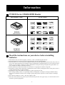
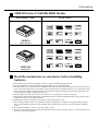
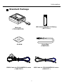
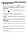
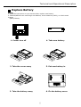
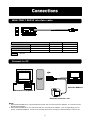
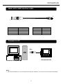
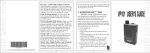
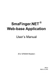
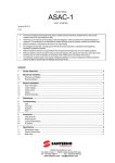
March 2007
REGISTERED TO ISO 9001:2000
8F, No.31, Lane 169, Kang-Ning St., Hsi-Chih Taipei Hsien, 221 Taiwan
Phone: (886) 2-2695-4214
FAX: (886) 1
2-2695-4213
www.gigatms.com.tw
Copyright©
GIGA-TMS INC.
Printed in Taiwan
Information in this document is subject to change without notice. No part of this document may be
reproduced or transmitted in any form or by any means, electronic or mechanical, for any purpose,
without the express written permission of GIGA-TMS INC.
REVISIONS
Rev Number
01
Date
March. 07
Notes
Initial Release
2
Contents
Information
....................................................................................................
4
...............................................
7
Technical and Operational Description
Connections
.................................................................................................... 13
Card Data Format
Specifications
...................................................................................... 15
................................................................................................ 16
Communication Protocol
..................................................................... 17
FCC COMPLIANCE STATEMENT
This equipment has been tested and found to comply with the limits for a Class A digital device,
pursuant to Part 15 of the FCC Rules. These limits are designed to provide reasonable protection
against harmful interference when the equipment is operated in a commercial environment. This
equipment generates, uses, and can radiate radio frequency energy and, if not installed and used in
accordance with the instruction manual, may cause harmful interference to radio communication.
Operation of this equipment in a residential area is likely to cause harmful interference in which
case the user will be required to correct the interference at his own expense.
3
Information
PCR120 Series 125KHz RFID Reader
MACHINE TYPE
FUNCTION
Single Cell
125K
RS-232
LR03 / AAA
8192
REC QUEUE
PCR120
AUTO
OFF
OFF
G N ET
Muti-Battery
NiHM / NiCd
ALKALINE
BEEP
F - MEM
512 KB
RTC
FMM
LCD
Muti-Battery
F - MEM
VER 1.2
RS232 Interface
Single Cell
125K
USB Ver 1.1
LR03 / AAA
8192
REC QUEUE
OFF
PCR120U
AUTO
OFF
G N ET
NiHM / NiCd
ALKALINE
BEEP
FMM
512 KB
RTC
LCD
VER 1.2
USB Interface
Read the instructions on your device before installing
batteries
1. Insert batteries into your device properly, with the (+) and (-) terminals aligned correctly.
2. Discharged batteries should be removed from equipment to prevent possible damage.
3. Store the batteries in a cool and dry place. [Batteries should be stored at temperatures between 50°F (10°C) and 77°F
(25°C), with relative humidity not exceeding 65 percent. Refrigeration of alkaline batteries is not necessary because
of their very good capacity retention. Excessive temperature cycling and storage at temperatures greater than 77°F
(25°C) should be avoided to maximize shelf life.]
4. Remove batteries from the electrical device if the device is not going to be used for a long time.
5. Keep battery contact surfaces and battery compartment contacts clean by rubbing them with a clean pencil eraser or
a rough cloth each time you replace batteries.
6. Keep batteries away from children. If swallowed, contact a physician at once.
7. Don't recharge a battery unless it is specifically marked "rechargeable". Attempts to recharge an alkaline battery
may cause an imbalance within the cell, leading to gassing and possibly explosion on either charge or discharge
cycles.
8. Don't dispose of batteries in a fire—they may rupture or leak.
9. Don't carry loose batteries in a pocket or purse with metal objects like coins, paper clips, etc. This will short-circuit
the battery, generating high heat.
4
Information
MFR120 Series 13.56MHz RFID Reader
MACHINE TYPE
FUNCTION
Single Cell
13.56M
RS-232
LR03 / AAA
8192
REC QUEUE
MFR120
AUTO
OFF
OFF
G N ET
Muti-Battery
NiHM / NiCd
ALKALINE
BEEP
F - MEM
512 KB
RTC
FMM
LCD
Muti-Battery
F - MEM
VER 1.2
RS232 Interface
Single Cell
13.56M
USB Ver 1.1
LR03 / AAA
8192
REC QUEUE
OFF
MFR120U
AUTO
OFF
G N ET
NiHM / NiCd
ALKALINE
BEEP
FMM
512 KB
RTC
LCD
VER 1.2
USB Interface
Read the instructions on your device before installing
batteries
1. Insert batteries into your device properly, with the (+) and (-) terminals aligned correctly.
2. Discharged batteries should be removed from equipment to prevent possible damage.
3. Store the batteries in a cool and dry place. [Batteries should be stored at temperatures between 50°F (10°C) and 77°F
(25°C), with relative humidity not exceeding 65 percent. Refrigeration of alkaline batteries is not necessary because
of their very good capacity retention. Excessive temperature cycling and storage at temperatures greater than 77°F
(25°C) should be avoided to maximize shelf life.]
4. Remove batteries from the electrical device if the device is not going to be used for a long time.
5. Keep battery contact surfaces and battery compartment contacts clean by rubbing them with a clean pencil eraser or
a rough cloth each time you replace batteries.
6. Keep batteries away from children. If swallowed, contact a physician at once.
7. Don't recharge a battery unless it is specifically marked "rechargeable". Attempts to recharge an alkaline battery
may cause an imbalance within the cell, leading to gassing and possibly explosion on either charge or discharge
cycles.
8. Don't dispose of batteries in a fire—they may rupture or leak.
9. Don't carry loose batteries in a pocket or purse with metal objects like coins, paper clips, etc. This will short-circuit
the battery, generating high heat.
5
Information
Standard Package
LR03-AAA ALKALINE 1.5V Battery
( BAT-T0010 )
Main unit
( PCR120/MFR120 )
Chain Sling
( TM09F1001 )
CD-ROM
RS232 Cable
( WAS-T0017 )
RS232 Cable for PCR120/MFR120 series
( WAS-T0017 )
USB Cable for PCR120U/MFR120U series
( WAS-1571 )
6
Technical and Operational Description
Front Panel and Operations
LCD Main Screen
Operation LED Indicator
Connector
Operate Keypad
Chain Sling Hole
RFID Card Scan Area
Battery Box
RFID Card Scan Area
Scan the RFID card to reader.
Operation LED Indicator
When encountering erroneous input, defective card, misread,bad memory or incorrectly
encoded data and so on, the device will turn on the ERROR indicator .
LCD Main Screen
Indicating the device is ready for use low battery in operational mode.
Connector
For connection to host computer and external Power .
Battery Box
Put the battery in box and hold battery .
Operate Keypad
Turn the PCR120/MFR120 on/off power and Operate.
Chain Sling Hole
Connect to chain sling.
7
Technical And Operational Description
LCD Display
Status Function Area
Main Display Area
Keypad Guidance Area
PROMAG
Status Function Area
1. Power Status
5. Decode Status
Battery Power Supply
Low Battery Power Supply
External Power Supply
EM
1K
4K
DS
UT
FL
2. Scan Status
or
Scaning
EM Card Decoded
Mifare 1K Card Decoded
Mifare 4K Card Decoded
Mifare DESFire Card Decoded
Mifare Ultralight Card Decoded
Felica Card Decoded
6. Guidance Number
3. Buzzer Status
xxxxxx
Buzzer ON
4. Event Status
x
x-x
Event
Current Record Number When Scanning or
Viewing Database
Main Menu Item When Operating Menu
Sub-Menu Item When Operating Submenu
Main Display Area
Display Date & Week & Time , Menu Item , Record Data , Parameter
Setting , Other Information
Keypad Guidance Area
1. Corresponding Key Power /Exit / Back / Cancel / No Key Function
2. Corresponding Key Up / Up scroll / Decrease/Scan Key Function
3. Corresponding Key Down / Down scroll / Increase/Event Key Function
4. Corresponding Key Menu / Enter / Save / Next / Yes Key Function
8
Technical And Operational Description
Function Menu
1. Profiles
2. Setting
3. Database
Display Machine ID 1-1. Machine ID
2 Characters
Default : 00
Display User Name 1-2. User Name
16 Characters Max
Display Mode 1-3. Display Format
ID Number
Set View Mode 1-4. View Mode
Big or Small
Default : Big
Set Scan Mode 1-5. Scan Mode
Button or Continuous
Default : Button
Set Back Light Duration 2-1. BackLight
00 ~ 255 Seconds
Default : 15 Seconds
Set Auto Power Off Duration 2-2. Auto Power Off
00 ~ 255 Seconds
Default : 30 Seconds
Set Power Mode 2-3. Power Mode
Switch Mode or Auto Power Off Mode
Default : Switch Mode
Set Operate Sound ON or OFF
2-4. Sound
Default : ON
Reset Default BackLight = 15 seconds
2-5. Reset
Auto Power Off = 30 seconds
Power Mode = Switch Mode
Sound = ON
Display Memory Status 3-1. Status
Used Space, Unused Space, Total Space
3-2. View
4-1. Date Format
4. Calendar
4-2. Set Date/Time
5. Information
Display all records in memory
Set Date Format Select Year / Month / Date
Date / Month / Year
Month / Date / Year
Default : Month / Date / Year
Set Date Year, Month, Date
Set Time Week, Hour, Minute, Second
5-1. Product Name, Product Description, Firmware Version
9
Technical and Operational Description
Display Information
Exceptional Indication
LCD Display message
Description
Counterplot
Check RTC !
The RTC is malfunctioning
( After scan card )
Set Date and Time
FLASH Full !
The record already is full.
( After scan card )
Download Records
and Erase Records
Check FLASH !
The record can’t write into the FLASH memory.
( After svan card )
Contect Agent
Decode Error !
Scan Card can’t decode.
( After scan card )
Scah Card again
or Change Card
No Record !
No Record in FLASH memory.
( Enter Database -View function )
Swipe Card
Record not empty !
The FLASH memory not empty.
( Enter Calendar function )
Download Records
and Erase Records
ISP MODE
Enter FMM Mode
( By communication command )
Update New Firmware
LED Indicator
Status
Green LED
Red LED
Buzzer
Read Card
Power On
Take turns blink
2 times
Beep. Beep.
X
Auto Power Off
Take turns blink
2 times
Beep. Beep.
X
Ready
Off
Off
X
O
Read OK
Blink
1 time
Off
Beep.
X
Read Error
Off
Blink
1 time
Beep. Beep. Beep.
X
Firmware Management Mode
Off
On
X
X
10
Technical and Operational Description
Operational Description
1. Powered by Battery
For normal use, the unit is powered by battery. Push the Power Switch Button“ “ for about 2 seconds to turn on the
unit. Also push the Power Switch Button“ “ for about 2 seconds to turn off the unit at Switch Mode. After the unit is
turned on, the power would be turned off automatically if there is no scanning a card on the unit in 30 seconds (default) at
Auto Power Off Mode. This means the unit would be turned off if no scanning a card again in every 30 seconds (default)
after every card scanning. It would have Low Battery Detect/Warning indication when the unit is powered by battery.
2. Powered by Cable
When PCR120/MFR120 is connected/disconnected to external power adapter by the WAS-T0017 RS232 cable or USB
port by the WAS-1571 USB cable,, it would be turned On/Off automatically. When the unit is connected with the PC
through the communication Cable (WAS-T0017 or WAS-1571) and the PC is running PCR120/MFR120 software and
the unit is turned on. Then you can do the unit Setting, Configuration or data downloading. When the device is powered
by cable from PC, the Power
would have no function and the unit would have no Low Battery Detect/Warning
“Switch
“
function.
3. Real Time Clock Setting
Before start using the unit, you must set the Real Time Clock (RTC) inside the unit to your local time. If there is no
battery for quite a while or it is powered by cable for quite a while this would cause Real Time clock (RTC)
malfunctioned due to no power supply. When put on the battery to turn on the unit and the Red/Green LED take turns to
blinks, this means the RTC is malfunctioning and you must do the RTC time setting before you use the unit.
4. Low Battery Detect
When the device is powered by battery, it would have Low Battery Detect function. When the battery goes low, the
LCD would display “
“ and you must change battery immediately ; otherwise, the unit would shut down any time
without pre-warning.
5. Scan RFID Card
When PCR120/MFR120 is showing the status of any function on the screen, after presenting a RFID card to PCR120/
MFR120 reader, PCR120/MFR120 is displaying card ID and record(s) information on the screen immediately. When
PCR120/MFR120 is not working for next card scan , PCR120/MFR120 reader will back to default screen automatically.
6. Operate for Calendar
Before setting calendar function, please delete remaining records from PCR120/MFR120 reader, if there are records in
the memory of PCR120/MFR120 , your operate setting for Calendar, PCR120/MFR120 reader will display ” Record no
empty” on the screen.
7. Memory Full Warning
Log database memory is full. You are not able to add any new records. Free the log database memory by uploading
the data to the PC.
8. Communication by WAS-T0017 (RS232 cable)
You must use external power when the PC connect to PCR120/MFR120 by WAS-T0017 RS232 cable, or else the
communication is not action. You should press any key on PCR120/MFR120 until the communication is finished, if you
don’t use external power.
9. Firmware Management Mode (FMM)
FMM allows you to quickly upgrade your PCR120/MFR120 internal firmware via com port and also check validity of
currently loaded firmware. Contact your dealer for most recent firmware upgrade files.
10. Database in memory
The PCR120/MFR120 allows you to manage database by software . The Logical Erase Database will logically clean
the database. The Recovery Database will recover the previous erase and not yet covered database. The record pointer
will return to the top of the database after any erase.
11
Technical and Operational Description
Replace Battery
Note:
1. Read the instructions on your device before replace new battery.
2. PCR120/MFR120 can used Single-cell alkaline, nickel-cadmium (NiCd), or nickel-metal
hydride
(NiMH) Battery
1. Power turn off
4. Take new battery
2. Take the cover away
5. Put new battery in
3. Take the battery away
6. Fix the battery cover
12
WAS-T0017 RS232 interface cable
DSUB 9P POWER JACK
DSUB 9P FEMALE PIN
+
-
2
3
5
FUNCTION
VCC +5V
TXD
RXD
GND
MINI USB 4P
1
2
3
4
No use
Connect to PC
RS-232
PORT
PCR120/MFR120
Personal Computer
External power DC +5V
Note:
1. When PCR120/MFR120 is connected/disconnected with an external power adapter, it would be turned
On/Off automatically.
2. When PCR120/MFR120 is not connected with an external power adaptor , the corresponding key for
power on PCR120/MFR120 needs to be pressed all the time during the communications with the PC.
13
Connections
WAS-1571 USB interface cable
1
1
USB 4P FEMALE PIN
1
3
2
4
FUNCTION
VCC
DD+
GND
MINI USB 4P
1
2
3
4
FUNCTION
VCC
RXD
TXD
GND
Connect to PC
USB
PORT
PCR120/MFR120
Personal Computer
Note:
1. When PCR120/MFR120 is connected/disconnected with USB port, it would be turned On/Off automatically.
14
CARD DATA STRING
STX
STX
A
DATE & TIME
WEEK & CARD TYPE & EVENT
DATE
SP
TIME
WEEK
CARD TYPE
DATE & TIME
DATE
TIME
SP
WEEK
YYYY/MM/DD
HH:MM:SS
SP
W
MM/DD/YYYY
HH:MM:SS
SP
W
DD/MM/YYYY
HH:MM:SS
SP
W
1. Date have 3 formats - YYYY/MM/DD, MM/DD/YYYY, DD/MM/YYYY
2. SP is the SPACE characters ( 20h ).
3. TIME is 24hrs .
WEEK & CARD TPYE
WEEK
CARD TYPE
SUN
0
Mifare 1k
1
MON
TUE
1
Mifare 4k
2
2
Mifare Ultrlight
3
WED
3
Mifare DESFire
4
THU
4
EM 125K
5
FRI
5
Felica
6
SAT
6
EVENT
EVENT CODE
EVENT
0
1
2
3
4
5
USER DEFINE
EVENT
6
7
8
9
15
FC
8 or 16 CARD ID
CR
CARD ID
CR
125KHz RFID Card for PCR120
EM compatible64 bits, ASK Manchester coding.
Reading distance 10~50mm (depends on card).
13.56MHz RFID Card for MFR120
Compatible ISO 14443A, ISO 18092.
Reading distance 10~40mm (depends on card).
RS-232
RS232 Interface
RS232 , Half-Duplex , 8N1 , 9600 bps
USB Ver 1.1
USB Interface
Full compliance with the USB Specification V 1.1
The device uses a Virtual Serial Port Driver, making it appear to
have the software like a standard RS232 Serial Port.
LCD
LCD Display
LCD type : FSTN
Dot arrangement :101 x 67 Dots Matrix LCD Module
Viewing direction : 6 O’clock
GNET
VER 1.2
RTC
8096
REC QUEUE
Single Cell
LR03 / AAA
AC
DC
Communication Protocol :
Version 1.2 (GNET V1.2)
CLOCK
Real Time Clock (RTC) module and back-up capacitor
Memory Size for Storing Data
CMOS Serial Flash Memory 512K bytes
Up to 8192 records ( 32 Bytes / Record )
Battery Power
Single-cell alkaline, nickel-cadmium (NiCd), or nickel-metal
hydride (NiMH) battery .
Power Supply from Cable
DC 5V , 200mA ( for RS-232 ) or USB Powered
Dimensions
L 58 x W 20 x H 47 mm
%
C/F
Environment
Operating Temp : 0 ~ +55℃
Storage Temp : -10 ~ +60℃
Humidity : 10 ~ 90 % relative
Mounting
Portable or Any surface
16
Handshaking
ACK
NACK
NACK
TIME OUT
TX1
RX
TX2
RX
TX3
RX
TX3
RX
TX4
TIME
OUT
RX1
ACK
RX2
NACK
RX
ERR
NACK
RX3
ACK
NO
RX4
WAIT
RX
PACKET
STX
CMD
CONTENTS
CR
STX
REPLY
CONTENTS
CR
ITEM
STX
CMD
CONTENTS
CHKSUM
CR
REPLY
Dec
2
ASCII
ASCII
ASCII
13
(78) 65
Hex
02
ASCII
ASCII
ASCII
0d
(4e) 41
Control Key
^B
ASCII
ASCII
ASCII
^M
(N) A
17
Function
Start of Text
Command Code
Contents Data
Check Sum
Carriage Return
(Negative) Acknowledge
Communication Protocol
PCR120/MFR120 Terminal has an extensive list of Commands that allow manipulating its internal
database, setting functional parameters and getting data on its current status.
There are 2 levels of access to the PCR120/MFR120 : User and Supervisor. Supervisor level is protected
by a Password. Sensitive data can be downloaded or altered only on the Supervisor level. General Terminal
data is available on the User level as well.
Command Index Table
Topic
ACCESS
DATABASE
Command
U
---
L
O
S
P
U
S
S
S
S
N
G
E
R
M
Contents
Description
Access Security Command
4 Characters for Login(0000)
New four characters
password
Database Commands
Number
Login
Logout
Set Password
Get Number of Record
Read Record by Number
Erase All Record
Rollback Record
Recovery All Record
General Commands
SETTING
U
S
U
S
U
U
S
S
F
S
T
J
I
X
B
C
Date,Time,Week
-
Reply Index Table
Reply
A
C
D
I
F
E
Contents
Reply Information
Checksum Error
Access Denied
Invalid Command or Data
Command Execution Failed
Database is Empty
18
Get Product Version
Set Date,Time and Week
Get Date and Time
Set Machine ID
Get Machine ID
Enter Firmware Management Mode
Get Register
Set register
Communication Protocol
Access Security Commands
LOGIN : (for Supervisor Access Level)
STX
L
STX
PASSWORD
A or D or I
PASSWORD
CR
CR
4 Characters for Login. 0000=Initial value
EXAMPLE
02
L
0000
02
A
0d
0d
Login password : 0000
02
D
0d
Login password command is not executed.
02
I
0d
Invalid password.
LOGOUT :
STX
O
CR
STX
A
CR
EXAMPLE
02
O
0d
02
A
0d
Logout
SET PASSWORD :
STX
STX
P
A or D or I
PASSWORD
PASSWORD
CR
CR
New four characters password
19
Communication Protocol
EXAMPLE
02
P
02
A
1234
0d
0d
Set new password : 1234
02
D
0d
Set new password is not executed.
02
I
0d
Invalid password
GET NUMBER OF RECORD :
STX
N
CR
STX
A
NUMBER
NUMBER
CR
Record Count . 4 Bytes Width ( 0000h ~ 0800h )
EXAMPLE
02
N
0d
02
A
000C
0d
The total of record count : 12
READ RECORD BY NUMBER :
STX
G
CR
STX
A
STX
E or D or F
DATA
DATA TIME
DATE TIME
20h
DATA
CR
20h + Record Data
DATE + TIME
EXAMPLE
02
G
0d
02
A
11/10/2004
10:39:23
Record data : ABCDEF
02
E
0d
Database is empty.
20
20
ABCDEF
0d
CR
Communication Protocol
ERASE ALL RECORD :
STX
E
CR
STX
A or D
CR
* ( Erase Duration : < 60 seconds )
EXAMPLE
02
E
0d
02
A
0d
D
0d
Erase all records.
02
Erase command is not executed.
ROLLBACK DATABASE READOUT TRANSACTION :
STX
R
CR
STX
A or D
CR
EXAMPLE
02
R
0d
02
A
0d
D
0d
Database is rollback.
02
Command is not executed.
RECOVERY ALL DATABASE READOUT TRANSACTION :
STX
M
CR
STX
A or I
CR
EXAMPLE
02
R
0d
02
A
0d
I
0d
Database is recovery.
02
Invalid command .
21
Communication Protocol
GET PRODUCT VERSION :
STX
F
STX
A
ROM No.
VERSION
CR
ROM No.
VERSION
CR
ROM-Txxxx , xxxx : Rom serial number
Vx.xxRm , Vx.xx : Firmware version x.xx , Rm : Modify m times
EXAMPLE
02
F
0d
02
A
ROM-T0571
,
V1.03R0
0d
ROM serial number = ROM-T0571
Firmware version = 1.03
Modify times = 0
SET DATE AND TIME :
STX
S
STX
A or I or D
YYYY
MM
DD
hh
mm
ss
YYYYMMDDhhmmss
CR
CR
Year (2000 - 20xx )
Month (01 - 12 )
Date ( 01 - 31 )
Hour ( 00 - 23 )
Minute ( 00 - 59 )
Second ( 00 - 59 )
EXAMPLE
02
S
02
A
200005051230006
0d
Set Date = 2000 / 5 / 5
Set Time = 12 : 30 : 00 , Saturday
02
I
0d
D
0d
Invalid Date/Time
02
Set Date/Time is not executed.
22
0d
Communication Protocol
GET DATE AND TIME:
STX
T
CR
STX
A
YYYYMMDDhhmmss
CR
EXAMPLE
02
T
02
A
0d
20001108142031
Get Date : 2000 / 11 / 8
Get Time : 14 : 20 : 31 , Thursday
02
F
0d
Get Date/Time is not set or invalid.
SET MACHINE ID:
STX
STX
J
00~255
A or I or D
CR
CR
EXAMPLE
02
J
00
02
A
0d
I
0d
0d
Set Machine ID : 00
02
Invalid command or data.
02
D
0d
Set Machine ID is not executed.
23
0d
Communication Protocol
GET MACHINE :
STX
I
STX
A
CR
00~255
CR
EXAMPLE
02
I
0d
02
A
00
F
0d
0d
Get Machine ID : 00
02
Get Identification is not set or otherwise invalid.
ENTER FIRMWARE MANAGEMENT MODE :
STX
X
CR
STX
A
CR
EXAMPLE
02
X
0d
02
A
0d
Enter firmware management mode
24
Communication Protocol
SET REGISTER :
STX
C
STX
A
REGISTER
PARAM
CHKSUM
REGISTER
,
PARAM
CHKSUM
CR
Register Address . 2 Bytes Width ( 00h ~ FFh )
Set Parameters of Register
C + REGISTER + , + PARAM
GET REGISTER :
STX
B
REGSTER
STX
A
PARAM
REGISTER
PARAM
CR
CHKSUM
CR
Register Address . 2 Bytes Width ( 00h ~ FFh )
Set Parameters of Register
REGISTER TABLE
Register
10h
11h
Function
Description
Auto Off Duration(Low byte) 00~FFh (0~ 255 second )
Auto Off Duration(High byte) 00h: Auto Power Off
FFh: Switch
Other: Real time
12h
Power Mode
13h
14h
15h
16h
17h
18h
Machine ID (High byte)
Machine ID (Low byte)
RTC cal. value
*
*
Back Light Duration
19h
Buzzer
1Ah
Date Format
00h: mm/dd/yyyy
FFh: yyyy/mm/dd
other: dd/mm/yyyy
1Bh
Display Mode
00h: Tracks Parallel
01h: Credit Card Mode
other: Tracks Series
1C~1Dh
*
2 Characters
00 ~ FFh
*
00~FFh (0~ 255 second )
00h: Off
FFh: On
*
0~1h: only 0 event
2h: 0~1 event
nh: 0~(n-1) event Max n=10
10~FFh: 0~9 event
1Eh
Option of event
1Fh
Scan Mode
00h: continuous Mode
other: Button Mode
20~2Fh
30~1FBh
1FC~1FFh
User Name
*
Password
16 Characters
*
4 Characters
25
CR