1
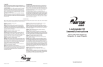
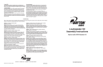
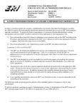
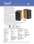
6. Install Grill
The grill has four neodymium magnets which are embedded in the
frame. These magnets are arranged to align with the screws that hold the
baffle in place. Simply place the grill on the baffle and align as necessary.
7. Test the speaker
Connect the speakers to your stereo system and play music through
the speakers to verify that the overall sound is full and smooth. If a
driver is not working or the sound is intermittent or distorted, please
see the troubleshooting section for possible remedies. In most cases
the cause of a problem will be traced back to improper wiring of the
crossover and not faulty drivers.
Break-In: Please allow a full two weeks of playing time at moderate
volumes before playing the system at high energy levels. This will allow
the drivers suspensions to properly break in before being subjected to
large excursions.
Care and cleaning
To protect the Dayton speaker system’s finish, use some care when
cleaning it. To remove dust from drivers, grills, or the cabinet tops, a
synthetic “feather duster” works well. For more stubborn dust on the
grills or woofers, a vacuum cleaner with gentle brush attachment may
be used. It is not recommended to use any type of cleaning apparatus
on tweeter domes; dust will not affect the sound, and the chance of
damaging the dome is high.
For cleaning streaks or fingerprints on the cabinet finishes, an
ammonia-based window cleaner is recommended. It will not affect the
finish and will leave a streak-free shine. It is important to use only very
soft, clean cloths, and to wipe gently at the surface. Intense scrubbing
or using cloths with debris on them may cause small swirl marks or
scratches. Of course, the best way to maintain the finish on the cabinet
is to prevent soiling it in the first place. Never place drinks or abrasive
objects on the top of the speaker.
Troubleshooting
Again, in most cases the cause of a problem will be traced back to the improper wiring of the crossover and not a faulty driver. Common mistakes:
using the wrong harness, improper polarity, bad or loose connections.
Problem: No output from speaker system.
Cause: Bad connection.
Solution: Check connections from the stereo to the input of the
speaker system. If OK, check the connection from the binding post
to tweeter and woofer input terminals. If this is OK, Test speaker on
another system. If sound comes out check initial stereo settings and
connections (speakers on/off). If there is no sound at all, please contact
your place of purchase immediately.
Problem: No output from woofer in individual speaker.
Cause: Bad connection or defective woofer.
Solution: Check connections from crossover board to woofer. If this
is OK, directly test the woofer by hooking it up to stereo system at
low volume setting. If sound comes out of the woofer, then go back
and check connections. If there is no sound at all, then woofer is likely
defective. Please contact your place of purchase immediately.
Problem: No output from tweeter in individual speaker.
Cause: Bad connection or defective tweeter.
Solution: Check connections from crossover board to tweeter. If OK, it
is possible to carefully test the tweeter by directly connecting it to your
stereo. Test at a very low volume for a brief period of time, at the level
of a loud whisper. If there is high-frequency sound, then go back and
check connections. If no sound at all, then tweeter is likely defective.
Please contact your place of purchase immediately.
Problem: There is sound from the speaker, but it is very quiet and
seems to be mostly treble or midrange.
Cause: Woofer and tweeter are wired backwards.
Solution: Immediately cease testing to prevent damage to the tweeter.
Check connections from crossover board to woofer and tweeter, making sure the high pass filter denoted with a “T” on the output terminal
is connected to the tweeter and the low pass filter denoted as “W” is
connected to the woofer.
Problem: Intermittent output of entire speaker, woofer, or tweeter.
Cause: Bad connection in wires or crossover board.
Solution: If entire speaker is intermittent, then check connections
between the input terminals and the crossover board. If just woofer or
tweeter is intermittent, check the wires going to the drivers. If these are
OK, check the connections of the components within the appropriate
section of the crossover.
© Dayton Audio
Dayton Audio UA701 Speaker Kit
Designed by Dr. Joseph D’Appolito
Problem: One speaker appears louder than the other.
Cause: Amplifier settings, environmental factors, psychoacoustics,
poor connection in crossover.
Solution: Check your amplifier to ensure that the balance is set even.
Next, check that one speaker isn’t closer to a wall, window, couch, or
other acoustically important object. This may affect perceived loudness
due to the addition or reduction of extra sound reflections. If this is the
case, physically switch the left and right speakers, and re-observe. If the
same location still sounds quieter, then it is the environment. If the quiet
speaker moves, then you may have a problem within the speaker. Often,
if you think one speaker is louder than the other, it will appear so. Have
someone help you do a blind test or take a break and allow time for your
brain to relax. The next day, if one still seems louder, investigate all connections within the crossover.
Problem: Speakers play well, but amplifier shuts down.
Cause: Amplifier does not have enough power or cannot handle
speaker impedance.
Solution: If using 4 ohm speakers, check receiver/amplifier manual to
see if it can handle 4 ohm speakers or if it has a low impedance setting.
If not, upgrade your amplifier. If the receiver/amplifier can safely handle
the speaker load, then it may simply not have enough power.
P.O. Box 52 • Springboro, OH • 45066-052 • Phone: (937) 743-8248
®
Loudspeaker Kit
Assembly Instructions
Problem: In stereo, speakers lack bass or image is unfocused.
Cause: Speakers are out of phase.
Solution: Check connections from amplifier to the speakers. Make
sure polarity is the same on both speakers. If correct, check the polarity
of connections going from binding posts to input on crossovers. If this
does not correct the problem, check polarity throughout the rest of the
system, looking for one driver that is wired incorrectly.
IMUA70109A
www.daytonaudio.com
Introduction
Loudspeaker Kit Assembly Instructions
Dayton Audio and Dr. Joseph D’Appolito teamed up to design and produce a world-class bookshelf loudspeaker system that would establish new
standards of audio excellence. The Usher 8945A woofer and Usher 9930-20 tweeter have been sonically matched and optimally paired in this
system. Great drivers, superbly constructed enclosures, and a great audio mind combine to produce an awesome home theater speaker system
with truly impressive playback performance. A 2,000 Hz crossover point is made possible by the very low resonance Usher 9930 tweeter, slightly
padded to smoothly match it to the woofer’s output. The tweeter employs a third-order electrical filter and the woofer uses a second-order electrical filter with a conjugate network.
The system’s on-axis frequency response is flat within ± 1.7 dB from 100 Hz to 20 K Hz, which is excellent by anyone’s standards. The low frequency -3 dB down-point is 41 Hz—very good for a bookshelf speaker system. The UA701’s detailed imaging creates a very wide and open sound
stage with “studio monitor”-type accuracy.
By following these instructions and assembling the speaker in a conscientious manner, you will be able to enjoy your investment for many
years to come. If there are any questions during the assembly process,
please contact your place of purchase.
Gather the Necessary Tools
The assembly of your speaker kit requires several basic tools and
supplies, though more advanced tools can be used if desired. The following list represents the basic tools that are required:
Hammer
#2 Phillips head screwdriver or power driver
Small wrench or pliers
Silicone adhesive or hot-melt glue gun
Scissors or utility knife (for cutting foam)
Workspace Considerations
As with any type of kit assembly, it is best to have a well-lit, large, clean
work area. This will save time by eliminating lost parts and preventing
assembly errors. When working with the cabinets, it is important to
cover the work surface with a cloth or foam layer to protect the speaker
finish. The foam wrap that is around the speaker cabinets will work well
for this, but make sure it is free from dust or other debris.
Getting Organized
To prepare for the kit assembly, begin with some basic unpacking
and organizing. Open the large speaker cabinet box and remove the
cabinet from the packaging. You will need to unwrap the cabinet itself,
saving the wrap to protect your work surface. Remove the baffle from
the cabinet and place the baffle screws somewhere safe. Unpack the
binding posts and other packaged items.
Assembly
Frequency Graph
Specifications: • Impedance: 4 ohms • Frequency response: 41 - 20,000 Hz • SPL: 86.5 dB 2.83V/1m • Power handling: 80 watts RMS
• Traditional cabinet dimensions: 17" H x 10" W x 12.5" D • Curved cabinet dimensions: 17" H x (10" front, 4.5" back) W x 14" D.
1. Install Binding Posts
The posts will need to be
“knocked” into place with
a hammer and secured
from the inside of the cabinet. Start by placing the
cabinet face-down onto
the work surface, being
sure that the cabinet is
firmly supported.
Remove the binding posts
from their package, and
unscrew all washers and
nuts from the shaft. Next,
remove the main nut that
is used to hold the speaker wire onto the terminals—this will prevent
them from getting damaged while the posts are being inserted.
Insert one of the post shafts into the hole and align it, ensuring the
wire through-hole is running vertically. Gently tap into place until the
shoulder is even with the rear of the cabinet.
Note: Excessive hammering is not necessary and may cause damage
to the finish of the cabinet around posts. Repeat the same process with
the second post.
Front
Back
Dimensions based on traditional cabinet design.
Crossover Diagram
Parts Inventory
Before beginning the assembly process, please read this manual in its entirety and confirm that you have all necessary components listed below.
If anything appears to be missing, please contact your place of purchase immediately
Qty
1
1
1
1
1
1
1
Description
Dayton custom ported .75 ft³ cabinet
Usher 9930-20 1" textile dome tweeter
Usher 8945A 7" carbon fiber/paper woofer
Optimized high pass filter
Optimized low pass filter
Input wiring harness (16" w/ .250" terminals)
Woofer wiring harness (12" w/ .110" and .187" terminals)
Qty
1
1
1
18
2
1
Description
Tweeter wiring harness (12" w/ .250" terminals)
Dayton heavy duty binding post pair
Acoustic foam 24" x 18" x 1-1/2" UL 94
#6 x 3/4" Pan head screws
36" Speaker sealing caulk
Assembly instruction manual
Once the posts have been knocked into place you will need to secure
them from the inside of the cabinet. A lock washer followed by a nut
should be installed to secure the posts to the cabinet. Next, install the
wire terminal tab, the second lock washer, the second nut, and then
tighten into place.
Now that the posts are fully secured, reinstall the colored knobs on the
outside of the cabinet. When viewed from the rear of the cabinet (terminals should be closer to the “bottom” of the cabinet), the “red” terminal
is normally positioned on the right-hand side.
2. Wiring and installing the crossovers
The crossover is composed of two sections (two boards): a low pass
filter for the woofer and a high pass filter for the tweeter. There is an
indicator on the printed circuit board near the output terminals of each
filter, “W” denotes the low pass filter and is for connection to the woofer
and “T” denotes the high pass filter and is for connection to the tweeter.
The input terminal for each board is indicated using “IN”.
Note: In most cases the cause of a problem will be traced back to improper wiring of the crossover so please double check your connections.
Wiring: Each kit includes input, woofer(s) and tweeter wiring harness
with the crossover boards.
Using the parts list, identify the correct harnesses and attach to the appropriate terminals on the crossover boards. The crossover board side
of the harness will always use the larger .250" connectors. Connect the
input wiring harness from both crossover boards to the binding posts
wire terminal tabs while paying close attention to polarity. The red wires
will connect to the terminals that are marked with a + sign.
Location: With the crossover boards in the cabinet and connected to
the input binding posts, identify a suitable mounting location making
sure both the woofer(s) and tweeter wiring harness will reach their
respective drivers. The best location for the low pass filter is on the bottom front half of the cabinet and the best location for the high pass filter
is across the center of the internal brace.
Mounting: Secure the crossovers to the inside of the cabinet with the
included #6 screws or with silicone or hot-melt glue. If using hot-melt
glue, it is recommended to place the glue on the surface of the cabinet
and then press the board into it. This prevents the glue from cooling too
rapidly or dripping onto the cabinet. For curved-sided cabinets, we recommend using the screws to secure the crossover boards. If you are
using silicone, it is easier to apply the glue to the back of the PC board.
Make sure the mounting location is horizontal, and place the board
into its location. Allow the silicone to cure for an hour or so before you
change the orientation of the cabinet.
3. Install damping material
Fully line the cabinet using the included 1-1/2" acoustic foam. One
sheet should be allocated for each cabinet—cut the foam to size and
then secure to the cabinet interior walls using a spray adhesive such
as 3M’s Super 77 or with hot-melt glue. Cut and piece the foam around
crossover boards and bracing. When using spray adhesive, please
follow the manufacturer’s instructions. It is best to apply the spray to the
foam itself, being sure to spray away from the cabinet to prevent getting
adhesive on the cabinet exterior. When using hot-melt glue, simply
place a few drops of glue at various locations on the rear of the foam
and press into place.
Note: Do not place foam directly on top of or underneath the
crossover boards.
4. Install the baffle
Press the baffle into the cabinet, working carefully to ensure that no
wires are trapped between the baffle and the cabinet. Rout the driver
wiring to their proper driver hole location. Once the baffle is fully
installed, it can be secured via the included machine screws and glued
into place if desired.
Note: Once the baffle is glued into place, making any changes to the
speaker becomes very difficult. Using the four machine screws by
themselves will have adequate holding power to prevent leaks and
vibrations of the baffle. However, for the utmost cabinet strength, the
baffle should be glued into place with polyurethane glue.
5. Install drivers in baffle
When mounting the drivers, start with the tweeter. This will leave the
large woofer opening to help the wiring and placement of the more
delicate tweeter. Identify the tweeter wiring harness and gently pull it
through the tweeter opening and attached the terminals while paying
close attention to the polarity of the connections. The red wires will
connect to the terminals that are marked with a “red” dot or “+” sign.
Repeat this step for the woofer(s).
All drivers should be lowered carefully into place on the baffle. Facing
the terminals towards the bottom of the cabinet is the generally accepted
orientation, though it is not a critical. Using the included screws and predrilled pilot holes carefully tighten the drivers down onto the baffle. Pay
particular attention to not over-tighten screws on drivers with stamped
steel or polymer frames, which can cause deformation of the flange.
Secure the drivers to the baffles with the included #6 screws. All screw
holes are pre-drilled so be sure to properly align the drivers with these
holes during installation. For all driver installations, some form of gasket material should be used between the driver frames and the baffle to
prevent air leaks and vibrations.