1
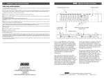
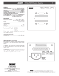
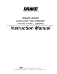
SCTeci Ethernet Control Interface
Instruction Manual
TM is a trademark of the R.L. Drake Holdings, LLC
is a registered trademark of the R.L. Drake Holdings, LLC
© Copyright 2014 R.L. Drake Holdings, LLC
P/N: 3852392B-01-2008
Printed in U.S.A.
2
Caution Statements
WARNING: TO PREVENT FIRE OR
ELECTRICAL SHOCK DO NOT
EXPOSE TO RAIN OR MOISTURE
CAUTION
RISK OF ELECTRIC SHOCK
DO NOT OPEN
CAUTION: TO REDUCE THE RISK OF ELECTRIC
SHOCK,
DO NOT REMOVE COVER
NO USER-SERVICEABLE PARTS INSIDE
REFER SERVICING TO QUALIFIED PERSONNEL
A product and cart combination should be moved with
care. Quick stops, excessive force and uneven
surfaces may cause the product and cart combination
to overturn.
The lightning flash with arrow head symbol, within an
equilateral triangle, is intended to alert the user to the
presence of uninsulated "dangerous voltage" within
the product's enclosure that may be of sufficient
magnitude to constitute a risk of electric shock to
persons.
The exclamation point within an equilateral triangle is
intended to alert the user to the presence of important
operating and maintenance (servicing) instructions in
the literature accompanying
the product.
WARNING: TO REDUCE THE RISK OF FIRE OR ELECTRIC SHOCK, DO NOT EXPOSE THIS PRODUCT
TO RAIN OR MOISTURE.
DO NOT OPEN THE CABINET, REFER SERVICING TO QUALIFIED PERSONNEL ONLY.
CAUTION: TO PREVENT ELECTRIC SHOCK, DO NOT USE THIS (POLARIZED) PLUG WITH AN EXTENSION
CORD RECEPTACLE OR OTHER OUTLET UNLESS THE BLADES CAN BE FULLY INSERTED TO
PREVENT BLADE EXPOSURE.
ATTENTION: POUR PREVENIR LES CHOCS ELECTRIQUES, NE PAS UTILISER CETTE FICHE POLARISEE
AVEC UN PROLONGATEUR, UNE PRISE DE COURANT OU UNE AUTRE SORTIE DE COURANT, SAUF SI LES LAMES PEUVENT ETRE INSEREES A FOND SANS EN LAISSER AUCUNE
PARTIE A DECOUVERT.
Important Safety Instructions
1. Read Instructions—All the safety and operating instructions should be read
before the product is operated.
2. Retain Instructions—The safety and operating instructions should be
retained for future reference.
3. Heed Warnings—All warnings on the product and in the operating
instructions should be adhered to.
4. Follow Instructions—All operating and use instructions should be followed.
5. Cleaning—Unplug this product from the wall outlet before cleaning. Do not
use liquid cleaners or aerosol cleansers. Use a damp cloth for cleaning.
6. Attachments—Do not use attachments that are not recommended by the
product manufacturer as they may cause hazards.
7. Water and Moisture—Do not use this product near water—for example,
near a bathtub, wash bowl, kitchen sink or laundry tub; in a wet basement;
or near a swimming pool; and the like.
8. Accessories—Do not place this product on an unstable cart, stand, tripod,
bracket, or table. The product may fall, causing serious injury to a child or adult,
and serious damage to the product. Use only with a cart, stand, tripod, bracket,
or table recommended by the manufacturer, or sold with the product. Any
mounting of the product should follow the manufacturer's instructions, and
should use a mounting accessory recommended by the manufacturer.
9. A product and cart combination should be moved with care. Quick stops,
excessive force, and uneven surfaces may cause the product and cart
combination to overturn.
10. Ventilation—Slots and openings in the cabinet are provided for ventilation
and to ensure reliable operation of the product and to protect it from
overheating, and these openings must not be blocked or covered. The
openings should never be blocked by placing the product on a bed, sofa, rug,
or similar surface. This product should not be placed in a built-in installation
such as bookcase or rack unless proper ventilation is provided or the
manufacturer's instructions have been adhered to.
11. Power Sources—This product should be operated only from the type of
power source indicated on the marking label. If you are not sure of the type of
power supplied to your home, consult your product dealer or local power
company. For products intended to operate from battery power, or other
sources, refer to the operating instructions.
12. Grounding or Polarization—This product may be equipped with a
polarized alternating-current line plug (a plug having one blade wider than the
other). This plug will fit into the power outlet only one way. This is a safety
feature. If you are unable to insert the plug fully into the outlet, try reversing
the plug. If the plug should still fail to fit, contact your electrician to replace
your obsolete outlet. Do not defeat the safety purpose of the polarized plug.
Alternate Warnings—If this product is equipped with a three-wire groundingtype plug, a plug having a third (grounding) pin, the plug will only fit into a
grounding-type power outlet. This is a safety feature. If you are unable to insert
the plug into the outlet, contact your electrician to replace your obsolete outlet.
Do not defeat the safety purpose of the grounding-type plug.
12 a. Mise à la terre ou Polarisation—Cet appareil est équipé avec un cordon
d'alimentation à trois fils. Il est a brancher sur une prise ayant un connecteur
a la terre. Assurez-vous que la connection a la terre ne manque pas.
13. Power-Cord Protection—Power-supply cords should be routed so that
they are not likely to be walked on or pinched by items placed upon or against
them, paying particular attention to cords at plugs, convenience receptacles,
and the point where they exit from the product.
NOTE TO CATV SYSTEM INSTALLERS:
THIS REMINDER IS PROVIDED TO CALL THE
CATV SYSTEM INSTALLER'S ATTENTION TO
ARTICLE 820 - 40 OF THE NEC THAT
PROVIDES GUIDELINES FOR PROPER
GROUNDING AND, IN PARTICULAR, SPECIFIES THAT THE CABLE GROUND SHALL BE
CONNECTED TO THE GROUNDING SYSTEM
OF THE BUILDING, AS CLOSE TO THE POINT
OF CABLE ENTRY AS PRACTICAL.
3
14. Outdoor Antenna Grounding—If an outside antenna or cable system is
connected to the product, be sure the antenna or cable system is grounded so
as to provide some protection against voltage surges and built-up static
charges. Article 810 of the National Electrical Code, ANSI/NFPA 70, provides
information with regard to proper grounding of the mast and supporting
structure, grounding of the lead-in wire to an antenna discharge unit, size of
grounding conductors, location of antenna-discharge unit, connection to
grounding electrodes, and requirements for the grounding electrode.
See Figure A.
15. Lightning—For added protection for this product during a lightning storm,
or when it is left unattended and unused for long periods of time, unplug it from
the wall outlet and disconnect the antenna or cable system. This will prevent
damage to the product due to lightning and power-line surges.
16. Power Lines—An outside antenna system should not be located in the
vicinity of overhead power lines, other electric light or power circuits, where it
can fall into such power lines or circuits. When installing an outside antenna
system, extreme care should be taken to keep from touching such power lines
or circuits as contact with them may be fatal.
17. Overloading—Do not overload wall outlets, extension cords, or integral
convenience receptacles as this can result in a risk of fire or electric shock.
18. Object and Liquid Entry—Never push objects of any kind into this product
through openings as they may touch dangerous voltage points or short-out
parts that could result in a fire or electric shock. Never spill liquid of any kind
on the product.
19. Servicing—Do not attempt to service this product yourself as opening
or removing covers may expose you to dangerous voltage or other hazards.
Refer all servicing to qualified service personnel.
20. Damage Requiring Service—Unplug this product from the wall outlet and
refer servicing to qualified service personnel under the following conditions:
a. When the power-supply cord or plug is damaged,
b. If liquid has been spilled, or objects have fallen into the product,
c. If the product has been exposed to rain or water,
d. If the product does not operate normally by following the operating
instructions. Adjust only those controls that are covered by the operating
instructions as an improper adjustment of other controls may result in damage
and will often require extensive work by a qualified technician to restore the
product to its normal operation,
e. If the product has been dropped or damaged in any way, and
f. When the product exhibits a distinct change in performance—this indicates
a need for service.
21. Replacement Parts—When replacement parts are required, be sure the
service technician has used replacement parts specified by the manufacturer
or have the same characteristics as the original part. Unauthorized substitutes
may result in fire, electric shock or other hazards.
22. Safety Check—Upon completion of any service or repairs to this product,
ask the service technician to perform safety checks to determine that the
product is in proper operating condition.
23. Wall or Ceiling Mounting—The product should be mounted to a wall or
ceiling only as recommended by the manufacturer.
24. Heat—The product should be situated away from heat sources such as
radiators, heat registers, stoves, or other products (including amplifiers) that
produce heat.
Figure A
Example of antenna grounding as per National Electrical Code, ANSI/NFPA 70
ANTENNA
LEAD IN
WIRE
GROUND CLAMP
ANTENNA
DISCHARGE UNIT
(NEC SECTION 810-20)
ELECTRIC
SERVICE
EQUIPMENT
GROUNDING CONDUCTORS
(NEC SECTION 810-21)
GROUND CLAMPS
NEC - NATIONAL ELECTRIC CODE
POWER SERVICE GROUNDING
ELECTRODE SYSTEM
(NEC ART 250, PART H)
4
Table of Contents / Specifications
TABLE OF CONTENTS
2
3
4
5
6
Caution Statements
Important Safety Instructions
Table of Contents / Specifications
General Description / Installation and Mounting
Front and Rear Panel Controls and Connectors
7
8
13
14
Setup and Programming
Operation
Service / If You Need To Call For Help
Warranty
SPECIFICATIONS
Functional
Products supported: SCT860 with PS100. SCT1860, SCT2860, SCT3860, &
SCT4860 with PS150 or PS151. DQT861 and MQM861.
LBS2250.
Network Interface: 10 Base T LAN or Internet via Ethernet Port, RJ-45.
Output Interface to Headend: RS232 serial port, DB9.
MAC address: Each SCTeci has an unique address.
IP address: User may program a static IP address or may choose it to
be assigned by DHCP.
Control security: System ID and Password, programmable from front panel.
PC software: No special software required. Displays on HTTP Web
Browser such as Microsoft Internet Explorer.
Downloads to multiple transcoders in a headend can be
enhanced by using the Drake SCT Control software.
Power Requirement 12 VDC nominal @ 250 mA, AC adapter supplied for
120VAC / 60 Hz
Mechanical and Environmental
Size: 19" W x 1.75" H x 4.0 D
Weight: 2.5 lbs.
Operating Temperature: 0 deg C to + 50 deg C ambient
Specifications subject to change without notice or obligation.
General Description / Installation and Mounting
5
SCTeci Front View
SCTeci ETHERNET CONTROL INTERFACE
ENTER
SCTeci
1.0
169.254.95.140
RESET
STATUS
C
R
T
A
SCTeci Rear View
RS232
GENERAL DESCRIPTION
The R.L. Drake model SCTeci is a professional quality
digital head end Ethernet Control Interface which accepts
RS232 serial data from the Drake family of transcoders.
The Drake transcoders supply the RS232 data by means
of their required Drake PS100 or PS151 power supplies.
The SCTeci then converts this RS232 data to Ethernet
format, thus permitting remote observation and control via
Internet or LAN. Control of up to 63 SCT860 transcoders
and up to 70 SCTx860 transcoders is possible using a
single SCTeci.
The SCTeci acts as a server, containing the software
needed to provide the required displays on a remote
INSTALLATION AND MOUNTING NOTES
This equipment is designed to be installed in a
standard 19” rack. When the unit is mounted above
or below other rack mounted equipment, it is recommended that air space of 1 unit high (1.75") be left
between the SCTeci and any other rack mounted
equipment.
ETHERNET
12 VDC
250 mA
computer. The remote computer can access the data
through the Internet or LAN using a standard web browser
such as Internet Explorer, Firefox or Netscape.
The SCTeci is compatible with SCT860, SCT1860,
SCT2860, SCT3860, and SCT4860 Transcoders when
they are used in conjunction with Drake PS100, PS150, or
PS151 Power Supplies.
The SCTeci is contained in a 1.75” x 19” standard rack
mounting. It has a front panel LCD display for ease of
programming and status monitoring, and is powered by an
external 12 volt, 250 mA DC supply.
Connect the DC power connector to an appropriate
source of 12 VDC with at least 250 mA DC capacity.
The SCTeci is always on once the DC power cord is
connected to its power source.
6
Front and Rear Panel Controls and Connections
FRONT PANEL CONTROLS AND INDICATORS
F1
F2
F3
F4
F5
ENTER
SCTeci
1.0
169.254.95.140
RESET
STATUS
C R
F6
F1, LCD Display – This display presents the selected
menu screen and the parameter settings. The backlight in
the display is on when power is applied. When connection
with a remote computer is established, it will indicate "Link
is Active" and will display the IP address.
F2,
Left and
Right Buttons – Use the left and right
arrow buttons to navigate from screen to screen to view a
parameter setting. These buttons are operational in the
view mode or the adjust mode. Using only these buttons
will not change any parameter settings. Once a connec-
tion is established with a remote computer, these buttons
will have no effect.
F3, Up and
Down Buttons – Use the up and down
arrow buttons to change the value of a viewed parameter
setting. The unit must be in the adjust mode in order for
these buttons to become active for changing a parameter
setting. If the unit is not in the adjust mode, pressing either
button will toggle between the SCTeci version number and
IP address, and 'Board Setup' and MAC number. Once a
connection is established with a remote computer, these
buttons will have no effect.
F4, ENTER button – Use the ENTER button to enter the
T
F7
A
F8
F9
adjust mode or to save and load a new setting or settings
after adjustment. To enter the adjust mode, hold for 2
seconds until a flashing "^" is observed in the upper right
hand corner of the display. After entering the adjust
mode, momentarily pressing the ENTER button again will
load and save any settings that may have been changed
using the F2 & F3 buttons.
STATUS LEDs
F5, RESET button -- This button re-initializes the microprocessor. It has the same effect as removing and
reapplying power. Use only if abnormal operation is
observed.
F6, "C" LED -- Lights continuously when unit is connected
to a network.
F7, "R" LED -- Dims when Ethernet packets are being
received.
F8, "T" LED -- Dims when Ethernet packets are being
sent.
F9, "A" LED -- Flashes continuously when unit is connected to power.
REAR PANEL CONNECTONS
RS232
ETHERNET
12 VDC
250 mA
R1
R2
R3
R1, RS232 – This is the RS232 serial connection to the
Drake transcoder power supply or supplies. It should be
connected to the 'RS232 IN' connector of the transcoder
power supply. Multiple power supplies should be "daisy
chained" as explained in the transcoder instructions.
R2, ETHERNET – This is the ethernet connector and
should be connected to the router, switch, or hub which
provides the gateway to the Internet or your LAN.
R3, 12 VDC -- Connect this terminal to a 12 VDC power
supply which has at least a 250 mA capacity. The center
terminal is positive. The SCTeci will be on as soon as
power is applied to this connector.
Setup and Programming
7
SCTeci Software Flow Chart
SCTeci 1.0
Board Setup
xxx.xxx.xxx.xxx
MAC xxxxxxxxxxx
Shows current
IP address
Unique
SCTeci
address
SYSTEM
PASWRD
xxxxx
xxxxxxxx
Enter 5 digit numeric
Enter 8 digit
system identifier. alphanumeric password.
DHCP ON
RS232 Baudrate
xxxxx
2400
4800
9600
19200
DHCP OFF
SUBNET mask
GATEWAY addr
xxx.xxx.xxx.xxx
xxx.xxx.xxx.xxx
Enter appropriate
12 digit address.
IP addr
xxx.xxx.xxx.xxx
Enter appropriate
12 digit address.
Enter appropriate
12 digit address.
DHCP enable
ON
OFF
CONNECTIONS & POWER UP
Connect the RS232 connector to the RS232 IN connector
of the Drake power supply used to power the Transcoders
to be controlled. If more than one power supply is in use
in your system, their RS232 connectors should be "daisy
chained" together.
Connect the ETHERNET connector to the router, hub, or
switch which provides access to the Internet or to the LAN
you intend to use.
Connect the 12 VDC connector to an appropriate source of
12 VDC with at least 250 mA DC capacity. The SCTeci will
activate as soon as power is supplied.
PROGRAMMING
Programming and viewing of the various setup and
operating parameters is accomplished using the front
panel back lit, two line, sixteen character wide LCD along
with the 4 arrow buttons and the ENTER button. The name
of the parameter is on the top line of the display and the
setting value is on the bottom line.
To observe a certain parameter setting without intending to
change its value, just use the left and right arrow buttons
to navigate through the menus shown in the above flow
chart. The current setting for each parameter is shown on
the bottom line of the display. Note that, depending upon
the DHCP enable setting, some screens are not needed
and will be skipped.
To make a change in the displayed parameter and its
setting, and if this is the initial setup, you will want to enter
the ‘adjust’ mode. To do this, press the ENTER button that
is located in the center of the four arrow buttons and hold
in for several seconds until a flashing caret ( ^ ) is
observed in the upper right hand corner of the display.
After you are in the adjust mode press the right arrow key.
This will cause an asterisk ( * ) to appear over one digit of
the parameter to be changed. Use the up and down arrow
keys to change each individual digit to the desired value
and use the left and right arrow keys to move the asterisk
to the next digit to be changed. Note that repeatedly
pressing the right arrow key when in the 'adjust' mode will
scroll through each changeable parameter one digit at a
time. Repeatedly pressing the left arrow button when in
the adjust mode will scroll left one digit at a time until the
first digit of a given parameter is reached. It will then
scroll through each of the changeable parameters without
producing an asterisk. Also note that you cannot enter the
'adjust' mode when on a screen that does not have a
changeable parameter. i.e.: 'Board Setup' and 'SCTeci /IP
number' screens.
When ENTER is pressed, the new settings will be loaded
and stored and the unit will exit the ‘adjust’ mode. You may
wish to not press ENTER until you have gone through all
screens and settings and then press ENTER to save and
load all changes in one step OR you can store just one or
several parameters at a time and reenter adjust mode to
set the next. Either method is acceptable.
SPECIAL CONSIDERATIONS
IP addr, GATEWAY addr, and SUBNET mask parameters
will not allow entries greater than 255. Therefore if you
wanted to change a number such as 165 to 225 and first
attempted to change the 1 to a 2, you would not be
permitted to do so. You would first have to change the 6 to
a 2 before changing the 1 to a 2.
SYSTEM can be any number between 11111 and 99999
excluding zeros. Each digit scrolls from 1 to 9, no 0.
PASWRD can be any eight alphanumeric characters,
including upper and lower case letters, numbers, and
punctuation - the SCTeci password. This is not to be
confused with the transcoder password, if used.
RS232 Baudrate: Make sure that the RS232 baud rate
that you select agrees with the RS232 baud rate of all
Drake power supplies to which the SCTeci is connected.
8
OPERATION
Once the SCTeci has been programmed with the desired
IP address, System ID, and password, it can be accessed
from any remote location on your LAN (Local Area
Network) or the Internet using a PC with a standard web
browser such as Internet Explorer, Netscape, or Firefox.
Establishing a Link
To obtain remote access, proceed as follows.
1)
Enter the IP address on the address line of your
browser and press ENTER. This will bring up a log-on
screen as shown below.
Selecting Desired Information
Notice the Select Mode window appearing at the top of this
screen. Clicking on the down arrow on the side of this
window will cause a drop down dialog box to appear
showing the available options as shown in the following
illustration.
You may select the desired option by moving the mouse
cursor over your selection and left clicking once on the one
desired.
2) Navigate to the SYSTEM ID window, and type in the
SYSTEM ID which you programmed into the SCTeci.
3) Navigate to the next window (using TAB or mouse),
and type in the password which you programmed into the
SCTeci. Skip this step if you do not know the password
and only wish to view and do not wish to change any
parameters. Password not required to view only.
4) When you are finished typing in this information, click
on the 'LOG ON' button. This will establish a link with the
SCTeci and will produce a screen similar to the one
shown below.
Displayed Information
Selecting SCT860 1–10 through SCT860 51–60 will
produce a table with six rows for each of the ten selected
transcoders, as shown in the previous two illustrations.
Selecting SCT860 61-63 will produce a table for only three
transcoders. The entries for each transcoder will be as
follows:
Transcoder ID
Demod Mode
Out of Lock; SNR (SCT860) or
Search; Out of Range; QAM
Version; Demod Error; SNR
Transcoder Baud Rate
View / Edit
No alarms; EAS; Over Temp
Button will not be present if
there is no transcoder with this
ID.
"Radio Buttons"
(See Text at right.)
Note that once a link is established, "Link is Active"
followed by the SCTeci IP number will appear on the
SCTeci display, and all front panel buttons except
RESET will be locked out.
Note: Allow ten seconds between stopping or closing
one logged on screen and attempting to log on again.
If PS15x – 1 through 7 is selected, the displayed information will be similar. However, row 3 will have slightly
different error information, and row 5 will show either the
Model and Version numbers, or the serial number, depending on the setting of the radio buttons in the lower left
corner of the window. (See illustration at left.)
See note on page 11 if FTP file transfer was used.
No radio buttons will be displayed if SCT860 entries are
selected since they do not have internally programmed
serial numbers.
OPERATION (contnued)
MODIFYING TRANSCODER PARAMETERS
To modify parameters of any monitored transcoder, you
must first do one of the following:
1) From the select mode menu, select 'single SCT860',
or 'PS15x Transcoder'. OR
2) Select any of the SCT860 or PS15x entries that have
active transcoders. Then press the 'View/Edit' button
beneath the data for the selected transcoder.
9
ENTERING OR CHANGING SCT PASSWORD
If the transcoders being accesssed have been set to
require a password, this SCT password must be entered
into the SCTeci. Do not confuse this with the SCTeci
PASWRD. Proceed as follows.
1) Click on the down arrow on the 'Select Mode:' window,
and choose 'Select SCT Password' from the resulting drop
down menu. This will produce a screen similar to below.
Either of these actions will produce a screen similar to the
one shown below which will contain the changeable
parameters for the selected transcoder.
Type desired password here.
1) Pressing the down arrow for a selected parameter
will produce a drop down menu which will give the
available choices.
2) Left click on the desired choice to select it.
3) On items which have no down arrow, the desired
parameters can be typed in directly. If an illegal entry is
typed in, an error message will be displayed.
4) Once you have changed all the parameters to your
satisfaction, press the 'APPLY' button. This will perform
the actual transcoder parameter changes.
The top cell of the 'Status' table on the upper right corner of
the display will show one of the following error messages:
Search; Out of Lock; Out of range; QAM Version; Demod
error; or if there are no errors, signal to noise ratio (SNR).
The bottom cell displays the transcoder baud rate.
The selection box in the upper left hand corner of this
window allows selection of the displayed parameters for
any other transcoder attached through PS15x power
supplies. The 'Block of 10' button will produce a table
which will show all 10 transcoders in the group containing
the transcoder displayed in the box.
2) Type the desired SCT transcoder password into the
box as shown in the above illustration. If the password is
already programmed into the SCT, stop here.
3) If the password in the SCTs needs entered or
changed, someone at the SCT transcoder location must
simultaneously hold down the left, center, and right buttons
on each SCT860 or PS151 for at least two seconds. This
will cause 'LOADING PASSWORD' to appear on the SCT
transcoder's display. Do this on each transcoder or power
supply that needs the new password loaded. If being
remote controlled solely with the SCTeci, a password of 0
should be entered. Factory default setting is 0.
4) Then click on the OK button. This will load the new
password into the transcoder. 'LOADING PASSWORD' will
disappear from the SCT transcoder's display and the new
password will be loaded.
PRESET CHANNELS
The preset channels function allows you to add to, modify,
or delete the selections that are available in the Demod
Mode selection window which appears when programming
individual SCTxxxx transcoders. To access this function,
select 'Preset Channels' from the Select Mode drop down
menu. You will be presented with a screen similar to the
following:
Note that the exact appearance of the screens shown here
will vary depending upon the web browser used, and to the
PC display resolution selected. In the above window,
Internet Explorer V6 was used with a screen resolution of
800 x 600 pixels.
Notice the 'Group' window on the left and the 'Add New
Channel', 'Edit Channel', and 'Delete Channel' buttons at
the bottom of the channels window.
10
Operation (continued)
Note: Adding, editing, or deleting of preset channels, after
the transcoder settings have been stored for a headend,
should be done using the SCT Control program software.
You can use the browser connection through the SCTeci to
make these changes initially, before the settings are
downloaded to the transcoders.
Adding a Channel
1) To add a channel using the web browser connection,
first select the group to which you want to add it. In this
case, in the Group window, select either 'HITS' or 'G10'.
2) Next, click the 'Add New Channel' button. This will
bring up a window similar to the following:
Deleting a Channel
1) From the Preset Channels screen, select the group
and channel that you wish to delete.
2) Press the 'Delete Channel' button. This will remove
the channel from the 'Preset Channels' list.
Editing a Group Name
The names of the groups listed in the 'Group' window of
the Preset Channels page can be altered to what ever
name the user prefers so long as the revised name
does not exceed eight characters. To do so, proceed
as follows:
1) From the 'Select Mode' window, select 'Preset
Channels'.
2) Select the group name you wish to modify in the
group window and click on the 'Edit Name' button.
This will bring up a screen similar to the following.
Type new name here.
Select group name here.
3) Proceed through the 'Preset number', ' Preset
Frequency', 'Preset Polarity', 'Preset Baudrate', and 'Preset
Interleave' boxes and enter the desired parameters for the
new channel.
4) Take care that you do not use a preset number that is
already listed. Then press the 'Add Channel' button to
add the new channel to the list.
The new channel will now be added to the 'Preset Channels' list and can be programmed into any SCTxxxx
transcoder by selecting it from the 'Demod Mode' drop
down menu which is available when programming a
particular transcoder.
Editing a Channel
1) To modify the parameters of a preset channel, select
the Group and channel you wish to modify from the 'Preset
Channels' screen.
2) Press the 'Edit Channel' button, which will bring up a
screen similar to the one shown at the top of this column.
3) Change the desired parameters.
4) When finished, press the 'Modify Channel' button.
This will change the parameters of the numbered preset
channel.
The modified channel can be programmed into individual
transcoders by selecting the modified channel from the
'Demod Mode' list as described above under 'Adding a
Channel'.
3) Select the group name you wish to modify from the
'Group' window. The selected name will appear in the
'Enter Name' box.
4) With the TAB key or mouse, move the cursor to
the 'Enter Name' box and type in the new name. Note
that if more than eight characters are typed in, the
additional characters will be ignored.
5) To record the new name, press the 'Change Name'
button. This will record the name and change back to
the previous screen.
The new name will be observed in the 'Demod Mode:'
window the next time any transcoder is selected from
the 'Select Mode' window, but will not be observed in
an actual transcoder until any parameter for that
transcoder is changed by means of the SCTeci.
OPERATION (contnued)
11
Downloading Setup Files from a PC - Files Stored
with the R. L. Drake SCT Control Program
If it is desired to download settings to one or multiple
transcoders from files that have been saved on your PC
using the R. L. Drake SCT Control Program, this may
be done using the SCT Control Program, version 2.3 or
later. It is OK if files were previously saved using an
earlier version, but only version 2.3 or newer can
download via the SCTeci instead of the RS-232 connection. Follow the procedure on the next page.
2) Use the Drake SCT Control Program from the
CDROM (included with the power supplies for the
transcoders) to setup the headend parameters as you
would do if using a RS-232 interface. If a headend
already has been locally setup and you want to copy
those settings (or possibly start with those settings
and make some edits), you may use the RS-232
connection to upload the headend settings to the SCT
Control Program running on the PC. Then disconnect
the RS-232 cable.
Using the R. L. Drake SCT Control Program with
the SCTeci
Combining the use of the SCTeci and the R.L. Drake
SCT Control program allows the operator to create
multiple headend files on a PC using the R.L. Drake
SCT Control Program. Then, instead of downloading
these configurations to the SCTs using a local cable
RS-232 connection or an RS-232 connection via a dialup modem, the download can be accomplished using
the SCTeci network connection.
3) Finalize any edits on the PC.
It should be noted that when used with the SCTeci
network interface, the SCT Control Program can only
download data to the transcoders . Thus it is not
possible to upload settings via the SCTeci to store
on the PC. A configuration may be copied from a
headend using the control program connected to the
headend via RS-232. After the settings are saved on
the PC, they can be copied to other remote headends
by downloading via a network and the SCTeci.
IMPORTANT: Close any browser connection to the
SCTeci before attempting to download using SCT
Control Program.
Downloading to Transcoders
To download to remote headend(s) from the SCT
Control Program via the SCTeci, proceed as follows.
Remember that you cannot upload current settings
from headends into the SCT Control Program files
using a connection via the SCTeci. You must have
these files already stored on the PC. If you need to
check to see that settings at a remote location are
matching what is in your PC, you can use a simple
browser connection to access the SCTeci and view
each transcoder's settings.
1) If the SCTs to be accessed have already been setup
with a password, it is suggested that you use the
procedure in the 'SCT Password Loading or Reset' on
the next page, or go physically to the equipment to set
any SCT, PS150 or PS151 passwords back to 0,
unless they are needed for RS-232 access protection.
There is no need to have SCT passwords when the
only remote access is via the SCTeci.
4) Make sure all headends that are going to receive a
download have been connected and set up with a
SCTeci connected to the Internet or LAN.
5) While still in the SCT Control Program, view the
multi transponder display. Click on the 'Download
Parameters to Multiple Transcoders' button.
6) On the next screen that comes up, check all
transcoders that need to receive the download. Then
be sure to check the box that indicates: 'Download
using SCTeci'. After checking this box, click on the
'Download' button.
7) A SCTeci download screen will appear. Entry fields
for IP address, system ID, and password need to be
filled in.
8) Select either HTTP or FTP protocol. In most installations the HTTP setting must be used. If you know that
any firewalls, routers, etc in line will allow FTP transfers, the FTP selection will be faster. The FTP setting
can usually only be used in installations that do not
have any address translation or firewall devices at the
SCTeci or at the PC browser. If FTP doesn't work,
select the HTTP setting.
9) Press Start to begin the transfer of new settings. If
any of the transcoders indicate a failure to load, repeat
the load operation a second time as certain conditions,
such as the transcoder not being locked to a satellite
signal, occur a second hit may be needed. If this is the
case, repeat this step.
Note: A Display Rack Load Status check box will
appear on screens that display info for multiple
transcoders. This selection is only meaningful when
the FTP setting is used (see paragraph 7 above). A
date and time of the last FTP transfer will be displayed. When this box is checked, row 5 will display a
FTP status of OK or FAILED. Refer to page 8 also.
12
Operation (continued)
Downloading Notes
When using the SCT Control Program with the SCTeci
to download stored configurations to transcoders, there
will be some buttons in the control program that will
not function with the SCTeci. These include uploading
functions and downloading to a single transcoder
buttons. To view current settings, edit, or to download
to a single transcoder only, over a network, use a web
browser connection directly to the SCTeci instead of
the SCT Control Program software.
Once the SCT Control program has been used to
download via the SCTeci, the IP address and system
ID that was entered will be saved by the PC program
and will be automatically associated with that headend
name in the future when the program is run on the PC.
Thus different IP addresses and IDs can be saved with
every headend name. At any time, the user may
overwrite any of this stored information with new
infromation if it has changed.
SCT Password Loading or Reset
This is the transcoder password, not the SCTeci
password. It is not necessary to password protect the
transcoders in most cases where the SCTeci is to be
the only mode of remote access because the SCTeci
provides the password access. Therefore, if no password has been loaded into the SCTs, you may leave
the password at 0.
If you still desire to load a password for the first time or
you desire to load a revised password into the
transcoders, or reset the SCT passwords back to 0,
then follow steps 1 through 5, below. If all of the SCTs
are already loaded with a common password, you will
not need to reload the transcoders, only give this
password to the SCTeci - skip step 3 in the sequence
below.
1) Before the SCTs are in 'LOADING PASSWORD',
using your browser, enter the IP address of the SCTeci
in the address box.
2) When the SCTeci screen comes up, using the
Select Mode drop down menu, highlight the 'Select
SCT Password' choice.
3) Next, a person at the headend location of the
SCTs, must press the three front panel buttons to
place the SCT into the 'LOADING PASSWORD'
mode. Do this to any SCT or PS151 that is to receive
the new password.
4) Using the SCTeci web page screen, enter the
desired password into the first empty box.
5) Click the OK box. This will cause the password to
be transferred to all SCTs that are in the loading
password mode. This completes the new password
transfer.
Downloading a New Webpage to the SCTeci
In the future, new web pages may be generated for
the SCTeci to incorporate some new function or
model. If this occurs, it is possible to download a new
web page to the SCTeci. The SCT Control Program
can be utilized to perform this download to the
SCTeci. Under the Tools heading, there is a dropdown
menu choice of 'Download Webpage to SCTeci' that
would be utilized. When a new page is issued, it will
be accompanied with instructions explaining where to
place the new file in order to make it available to the
program.
This function uses FTP and in most cases will need
to be performed by using a LAN connection.
Service / If You Need To Call For Help
SERVICE INFORMATION
You may contact the R.L. DRAKE Service Department for
additional information or assistance by calling
+1 (937) 746-6990, Monday through Friday, between
8:00 A.M. and 4:00 P.M. Eastern Time, except on holidays.
You may also contact the R.L. DRAKE Service Department by
E-mail at the following address:
[email protected]
or by Telefax:
+1 (937) 806-1510.
IF YOU NEED TO CALL FOR HELP
Call our Customer Service/Technical Support line at
+1 (937) 746-6990 between 8:00 A.M. and 4:00 P.M.
Eastern Time, weekdays. Please have the unit’s serial
number available. We will also need to know the specifics
of any other equipment connected to the unit.
When calling, please have the unit up and running, near
the phone if possible. Our technician(s) will likely ask
certain questions to aid in diagnosis of the problem. Also,
have a voltmeter handy, if possible.
R.L. DRAKE also provides technical assistance by
e-mail: [email protected]
or by Telefax: +1 (937) 806-1510.
Many of the products that are sent to us for repair are in
perfect working order when we receive them. For these
units, there is a standard checkout fee that you will be
charged. Please perform whatever steps are applicable
from the installation sections of the Owner's Manual
before calling or writing—this could save unnecessary
phone charges. Please do not return the unit without
contacting R.L. DRAKE first: it is preferred to help
troubleshoot the problem over the phone (or by mail) first,
saving you both time and money.
Inside the carton, enclose a note with your name,
address, daytime phone number, and a description of the
unit’s problem.
The unit must be sent to the following address:
Service Department
R.L. DRAKE HOLDINGS, LLC
710 Pleasant Valley Drive
Springboro, Ohio 45066 U.S.A.
Be sure to include your street address which will be
needed for UPS return. UPS Surface (Brown Label) takes
7-10 days to reach us depending on your location, Blue
takes 2-3 days.
13
Should you want to return your unit for service, package
the unit carefully using the original carton or other
suitable container.
Write your return address clearly on the shipping carton
and on an enclosed cover letter describing the service
required, symptoms or problems. Also include your
daytime telephone number and a copy of your proof of
purchase.
The unit will be serviced under the terms of the
R.L. DRAKE COMPANY Limited Warranty and returned
to you.
Red is an overnight service. Send the unit in a way that it
can be traced if we can’t verify receipt of shipment. We
suggest UPS or insured postal shipment.
If the unit is still under the original owner’s warranty,
R.L. DRAKE will pay the cost of the return shipment to
you. Our return shipping policy is that we will return it
UPS Brown if received Brown or by US Mail, it will be
returned Blue if received Blue or Red—or it will be
returned however you prefer if you furnish the return cost
for the method you select.
If the unit is out of warranty, use one of the following
methods for return shipment:
1) You designate billing to American Express, VISA,
MasterCard or Discover card;
2) You prepay the service charges with a personal check,
or
3) You specify some other method of return and payment.
When calling, the technician can estimate the repair
charges for you over the phone. This is another good
reason to call before sending a unit in for repair.
Typically, equipment is repaired in five to ten working
days after it arrives at R.L. DRAKE if we have all the
facts. If we must call you, it may take longer. R.L.
DRAKE is not responsible for damage caused by lightning, nonprofessional alterations, “acts of God”, shipping
damage, poor storage/handling, etc. R.L. DRAKE will
make note of any shipping damage upon receipt.
You will need to send proof of purchase to receive
warranty service. Typically, a copy of the invoice from an
R.L. DRAKE dealer will suffice. The warranty is for the
original owner only and is not transferable.
14 Warranty
Three Year Limited Warranty
R.L. DRAKE COMPANY warrants to the original purchaser this product shall be free from defects in material or
workmanship for three (3) years from the date of original purchase.
During the warranty period the R.L. DRAKE COMPANY or an authorized Drake service facility will provide, free of
charge, both parts and labor necessary to correct defects in material and workmanship. At its option,
R.L. DRAKE COMPANY may replace a defective unit.
To obtain such a warranty service, the original purchaser must:
(1) Retain invoice or original proof of purchase to establish the start of the warranty period.
(2) Notify the R.L. DRAKE COMPANY or the nearest authorized service facility, as soon as possible after discovery
of a possible defect, of:
(a) the model and serial number,
(b) the identity of the seller and the approximate date of purchase; and
(c) A detailed description of the problem, including details on the electrical connection to associated equipment and
the list of such equipment.
(3) Deliver the product to the R.L. DRAKE COMPANY or the nearest authorized service facility, or ship the same in
its original container or equivalent, fully insured and shipping charges prepaid.
Correct maintenance, repair, and use are important to obtain proper performance from this product. Therefore
carefully read the Instruction Manual. This warranty does not apply to any defect that R.L. DRAKE COMPANY
determines is due to:
(1) Improper maintenance or repair, including the installation of parts or accessories that do not conform to the quality
and specifications of the original parts.
(2) Misuse, abuse, neglect or improper installation.
(3) Accidental or intentional damage.
All implied warranties, if any, including warranties of merchantability and fitness for a particular purpose, terminate
three (3) years from the date of the original purchase.
The foregoing constitutes R.L. DRAKE COMPANY’S entire obligation with respect to this product, and the original
purchaser shall have no other remedy and no claim for incidental or consequential damages, losses or expenses.
Some states do not allow limitations on how long an implied warranty lasts or do not allow the exclusions or limitation
of incidental or consequential damages, so the above limitation and exclusion may not apply to you.
This warranty gives you specific legal rights and you may also have other rights which vary from state to state.
This warranty shall be construed under the laws of Ohio.
For Service, contact:
R.L. DRAKE HOLDINGS, LLC
710 Pleasant Valley Drive
Springboro, Ohio 45066 U.S.A.
Customer Service and Parts Telephone: +1 (937) 746-6990
Telefax: +1 (937) 806-1510
World Wide Web Site: http://www.rldrake.com
R.L. Drake Holdings, LLC
710 Pleasant Valley Drive
Springboro, Ohio 45066 U.S.A.
Customer Service and Parts Telephone: +1 (937) 746-6990
Telefax: +1 (937) 806-1510
World Wide Web Site: http://www.rldrake.com