1
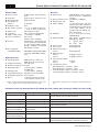
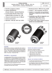
Electro-Optical Absolute Encoders CRD 58, 65, 66 and 105 Bus data Electrical data Sensor system: Resolution: Measuring range: GaAlAs diodes, photo-transistor array 8192 positions revolution, max. 4096 revolutions Total number of positions: 225 (25 Bits) Graduation code: Gray Max. position variance: ≤ 2' 38" at 4096 positions/rev. ≤ ±1'59 at 8192 positions/rev. Output code: Natural binary or Gray Code sense: CW or CCW; (programmable) Supply voltage range: + 13,5 VDC to + 30 VDC Power consumption: PD ≤ 3,5 W (Inrush current ≤ 300 mA) Interface: Line driver in acc. with RS 485; galvanic separation is achieved with an opto-coupler. Supply voltage galvanic separation is achieved with DC/DC-converter Electromagnetic compatibility (EMC): EN 61000-4-2 (ESD), EN 610004-4 (Burst), EN 61000-6-4 (Emission) Mechanical data Operating speed: 3000 rpm max. (continuous) 4000 rpm max. (short period) Angular acceleration: 105 rad/s² max. Moment of inertia (rotor):45 gcm² Operating torque: ≤ 5 Ncm (8 Ncm - CRD 66) (at 1000 rpm) Starting torque: ≤ 1 Ncm (4 Ncm - CRD 66) Permissible shaft load: 250 N max. (axial and radial) Bearing life expectancy: 109 revolutions * Mass: ca. 0.5 kg with round connector ca. 0.7 kg with connecting cap * At max. shaft load and working temperature between - 20 °C and + 60 °C. Higher values are permissible with lower loads. Specification: PROFIBUS-DP, Slave stations SPC3 Siemens PROFIBUS controller Data transmission rate: 9.6 kBaud to 12 MBaud Manufacturer code: 1962H Station address: 1 to 126, default value: 123; with variant Z the station address is set with DIP switches; with variant L the station address can be changed with the DDLM_Set_ Slave_Add service GSD File: in acc. with DIN 19245-3, PROFIBUS-DP Diagnosis LEDs*:UBS (green)-VS Supply voltage SRD (green) - SRD C (green)-Class Err (red) -Error Freeze mode: being supported Sync. mode: being supported Automatic baud rate search: being supported Diagnosis bytes Class 2: 63 Diagnosis bytes Class 1: 16 Diagnosis bytes User-Parameter bytes: Class 2: 22 bytes Class 1: 2 bytes Configuration options: D0 (1 Word Input, consistent) - Class1 D1 (2 Word Input, consistent) - Class1 F0 (1 Word Input / Output, consistent) - Class2 F1 (2 Word Input / Output, consistent) - Class2 * True table according connector arrangement supplied with each item. Parameters which can be programmed (via DDLM_Set_Prm / DDLM_Data_Exchange / DDLM_Set_Slave_Add) Value range Description of parameter Code sense CW, CCW Direction of rotation when looking towards the shaft: CW (clockwise), CCW (counter clockwise) Class 2 functionality enable / disable Enable for class 2 functionality Diagnosis routine yes / no Diagnosis routine for the encoder Scaling function enable / disable Enable for programming the parameters Resolution and Total number of positions Resolution: positions per revolution 1 to 8192 positions per revolution Resolution (number of positions per revolution) Total number of positions 1 to 33.554.432 Total number of positions "Reference value (DDLM-Data_Exchange)" 0 to (Total number of positions -1) Value displayed at the reference point Station address 1 to 126 Identification of the station within the bus network (can only be programmed with variant L via RS 25 connector) CRD 10534 HE / page 2