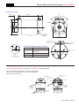
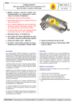
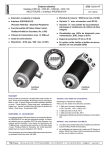
1
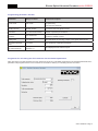
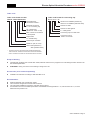
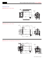
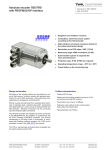
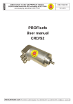
Electro-optical Absolute Encoders CRD/S3 series with SIL2 certificate MULTITURN PROFIsafe Interface CRD 12098 GE 04 / 2011 ■■ Compact and robust design for mechanical engineering and industrial plant applications ■■ PNO Profisafe Certificate No. Z20020 SIL2 according to TÜV certificate Nr. 44 799 11 391019-001 ■■ With PROFIsafe Interface to PROFIsafe-Profile for Safety Technology, Version 1.30, No. 3.092/ Version 2.00, No.3.192 (PNO) ■■ DP-Slave Class 2 functionality in accordance with Profibus-Profile for Encoder, No. 3.060 (PNO) ■■ Total number of positions: 225 (25 bits) max. ■■ With Velocity signal depending on rotation sense, gating time adjustable ■■ SIL2 Certificate in preparation ■■ Operating speed up to 2500 min-1 ■■ Protection grade IP 65 or IP 66 Optonal: Flange, housing and connecting cap in stainless steel - series "SRD" ■■ Diagnosis LED‘s for supply voltage, SRD, Class 2 and Error General description Construction The encoder CRD/S3 has been designed according to the PROFIsafe profile for safety technology to the PNO standards No. 3.092/ 3.192 (PNO). The protocol meets the DP slave class 2 functionality to PNO No. 3.060 and is described in the TWK user manual no. CRD 12099. Flange and housing of aluminium - respectiny stainless steel for SRD series - 12 mm ball-bearings with Nilos ring seal or radial packing ring seal - code disk of glass or of deformation resistant plastic - GaAlAs diodes - photo-transistor array with comparator and trigger circuits for long-term stabilization of the sensor systems gate array - SMD technology - additional implementations for safety functions to comply with SIL2 to IEC 61508. In addition to the angle position a velocity measurement signal is generated via the position data. The gating time of the velocity measurement is adjustable in the range of 1...255 ms. The PROFIsafe-Profile has been developed for safety relevant applications where human lives and environmental objects may be exposed to danger. In case of any unexpected event the device should revert to a fail-safe operation. To comply with this requirement the model CRS/S3 encoders feature additional surveillance functions which are described in the manual no. CRD 12099. The SPC3 Siemens PROFIBUS controller has been implemented at the output interface. The maximum data transmission rate is 12 MBaud. To guaranty a fail safe operation, a fail safe master, e.g. Siemens F-CPU with S7 Distributed Safety must be used. Connecting cap T-coupler functionality with integrated addressing code Connection leads and functions: 1 cable for the supply voltage (+ VS = 24 VDC, - VS = 0 VDC), M12 cable gland 1 cable for Bus in ( A, B ), M16 cable gland 1 cable for Bus out (A‘, B‘), M16 cable gland The station address and bus-termination resistors are set with DIP switches in the connecting cap. Because of different parameter and diagnosis data the CRD/ S3 ist not compatible to the preceding model CRD/S2. TWK-ELEKTRONIK GmbH · PB. 10 50 63 · D-40041 Düsseldorf · Tel.: +49/211/63 20 67 · Fax: +49/211/63 77 05 · [email protected] · www.twk.de Electro-Optical Absolute Encoders series CRD/S3 Electrical data Safety Data (IEC61508) ■■ Sensor system: GaAlAs diodes, photo-transistor array ■■ Resolution (max.): 8192 positions per revolution ■■ Measuring range: 4096 revolutions ■■ Total number of positions: 225 (25 bits max.) ■■ Graduation code: Gray ■■ Max. position variance: ≤ ± 2‘ 38“ at 4096 positions/rev. ≤ ± 1‘59 at 8192 positions/rev. ■■ Output code: Natural binary ■■ Velocity signal: depending on rotation sense, 16 bit, unit: steps/gating time ■■ (the gating time is programmable in the range of 1 to 255 ms, default: 10 ms) ■■ Code sense: CW or CCW; (programmable) ■■ Supply voltage range: + 13,5 VDC to + 30 VDC ■■ Power consumption: PD ≤ 3,5 W (Inrush current ≤ 300 mA) ■■ Interface: Line driver in acc. with RS 485; galvanic separation is achieved with an opto-coupler. Supply voltage galvanic separation is achieved with DC/DC-converter ■■ Electromagnetic compatibility (EMC): EN 61000-4-2 (ESD) EN 61000-4-4 (Burst) EN 61000-6-4 (Emission) According to IEC 61508: Bus data PROFIsafe-Profile for Safety Technology (No. 3.092/ 3.192 - PNO) Profibus-Profile for Encoder (No. 3.060 - PNO) Data transmission rate: 9,6 kBaud to 12 MBaud Manufacturer code: 1962h Stations address: 1 to 126 Default value: 123 adjustable via DIP switches GSD File: in acc. with DIN 19245-3, PROFIBUS-DP Diagnosis LED's*: UB (green) - Supply voltage SRD (green) - SRD C (green) - Class Err (red) - Error Freeze mode: not supported Sync mode: not supported Automatic baud rate search: being supported Diagnosis bytes Class 2: 66 Diagnosis bytes User-Parameterbytes Class 2: 45 Bytes Configuration options: PROFIsafe, Class 2 -Encoder □PFH = 4,35 x 10⁻⁷ 1/h □SFF = 98 % □HFT = 0 □SIL2 According to EN ISO 13849-1: □MTTFD > 100 years □DC = 98 % □Category 2 □Performance Level D Mechanical data Operating speed: Angular acceleration: Moment of inertia (rotor): Operating torque: 2500 min -1 max 105 rad/s² max. 45 gcm² ≤ 5 Ncm (8 Ncm - CRD66) (at 1000 rpm) Starting torque: ≤ 1 Ncm (4 Ncm - CRD66) Permissible shaft load: 250 N max. (axial and radial) Bearing life expectancy: 109 revolutions * Mass CRD 58, 65 and 66: ca. 0.7 kg with connecting cap CRD 105: ca. 1.4 kg with connecting cap * At max. shaft load and working temperature between - 20 °C and + 60 °C. Higher values are permissible with lower loads. Specification: Environmental data Operating temperature range: Storage temperature range: Permissible rel. humidity: Resistance to shock: - 20 °C to + 60 °C - 20 °C to + 60 °C 85 % without condensation 200 m/s²; 6 ms (DIN IEC 68) Resistance to vibration: 5 Hz to 2000 Hz; 100 m/s² (DIN IEC 68) Protection grade (DIN 40 050) IP 65 (Nilos ring) CRD 58, 65 and 105: CRD 66: IP 66 (radial packing ring) IP 00 (when not mounted) Connecting cap: * True table according to the connector arrangement will be supplied with each item. CRD 12098 GE / Page 2 Electro-Optical Absolute Encoders series CRD/S3 Programming parameter: Encoder Parameter Range of values Parameter description Code sense CW, CCW Direction of rotation when looking towards the shaft: CW (clockwise), CCW (counter clockwise) Scaling function disable, enable Enable for programming the parameters Resolution and Total number of positions and of the preset function Resolution 2 to 8192 Positions/360° Number of positions per revolution Total number of positions 2 to 33.554.432 Total number of positions in steps ( Total number of positions = resolution x number of turns) Gating time 1 to 255 ms Time intervall for the counting of steps of the speed measurement Standard Parameter CRC 1 to FFFF CRC-Checksum of standard parameters Reference value (by data exchange) 0 to (Total number of positions -1) Value displayed at the reference point Programme for calculating the CRC checksum via the standard parameters After changing an encoder parameter, the CRC checksum has to be re-calculated and entered in the "Standard Parameter CRC" parameter. The programme PsCrc.exe is enclosed on CD-ROM on delivery for calculating the CRC checksum. CRD 12098 GE / Page 3 Electro-Optical Absolute Encoders series CRD/S3 Programming parameter: F-Parameter Parameter Range of values Default Parameter description F_Check_SeqNr 0: NoCheck NoCheck This parameter defines whether or not the consecutive number shall be included in the CRC2 signature. F_Check_iPar 0: NoCheck NoCheck This parameter defines whether or not the checksum of the individual parameters CRC3 shall be included in the CRC2 signature. F_SIL 01b: SIL2 SIL2 SIL2 (Safety Integrity Level) to IEC 61508 (Functional safety of electrical/ electronic/programmable electronic safety-related systems) F_CRC_Length 2-Byte-CRC 00b: 3-Byte-CRC (V2-Mode) 01b: 2-Byte-CRC (V1-Mode) 10b: 4-Byte-CRC (optional V1/ V2 Mode) CRC Test value (of F- useful data) F_Block_ID No F_iPar_CRC No F_iPar_CRC fix adjusted F_Par_Version 00b: V1-mode 01b: V2-mode V1-mode Parameter version F_Source_Add 1-65534 2001 This parameter is allocated through the SIMATIC manager automatically. F_Dest_Add 1-65534 123 This parameter must agree with the address in the connecting cap. F_WD_Time 1-65536 ms 2000 A valid current Safety telegram from the F-CPU must come inside the watchdog time. F_ParCRC (CRC1) 0-65535 CRC-Sum of the F-Parameter from F_Prm_Flag1 Data format Output data: Host to slave Octet 1 MSB * Octet 2 Octet 3 Octet 4 Preset value Octet 5 LSB MSB Octet 6 Dummy Octet 7 Octet 8 LSB Octet 9 Octet 10 F-Data * Preset control: Bit 31: 1/O Input data: Slave to host Octet 1 MSB Octet 2 Octet 3 Position value Octet 4 Octet 5 LSB MSB Octet 6 Velociity Octet 7 LSB Octet 8 Octet 9 Octet 10 F-Data CRD 12098 GE / Page 4 Electro-Optical Absolute Encoders series CRD/S3 Order code Order code format encoder Order code format for connecting cap CRD58-4096R4096S3Z01 Z D-P 3 L 4 -23 Electrical and/or mechanical variants * Electrical connection Z = via connecting cap S3 = PROFIsafe (Profile No. 3.092 / 3.192) Max. number of revolutions to be acquired Output code R = natural binary Variant 23 for CRD/S3 (aluminium) Variant 27 for SRD/S3 (stainless steel) Number of LEDs Number of cable glands P = cable glands Connecting cap for model CRD Connecting cap for variant “Z” encoder Positions per revolution Model No. (58, 65 or 66) Series CRD (aluminium) SRD (stainless steel) * The basic versions in accordance with the data sheet bear the code number 01. Variations from the basic version are indicated with a consecutive number and are documented in our works. Scope of delivery CD-ROM with profisafe user manual CRD 12099, GSD file and the PsCrc programme for calculating the CRC checksum for the standard parameters. STD25WS17 mating connector for the heating in design form 105. Accessories (to be ordered separately) Installation accessories according to data sheet MZ 10111 Documentation Relevant profisafe user manual CRD 12099 The connection assignment enclosed with the device The TZY10206 installation instructions enclosed with the device Procurement source for the PNO specifications: PROFIBUS Nutzerorganisation e. V., Haid-und-Neu-Str. 7, D-76131 Karlsruhe www.profibus.com CRD 12098 GE / Page 5 Electro-Optical Absolute Encoders series CRD/S3 Dimensions in mm Model No. 58 with synchro-flange +0,2 14 -0,5 125 ±0,8 95 4 3 6 38 ca. 54 ø6 f7 ø65 -0,1 ø58 -0,1 ø50 f7 M4 x 5 +1.5 3x120˚ ca. 107 42 Model No. 65 with synchro-flange +0,2 25 -0,5 127 ±0,8 M5 x 9 +1,5 3x120˚ ø12 h7 ca. 54 38 ø65 -0,1 ø60 -0,1 ø45 f7 2 4,5 1,5 +0,1 2,5 -0,5 97,5 55 ca. 109 Model No. 66 with clamping flange and shaft with flat 30 +0,2 -0,5 125 ±0,8 95,5 10 3,1 6,2 18 ca. 107 38 ca. 54 ø10 f6 9 ø64 -0,1 ø59 -0,1 ø36 f8 M4 x 9 +1.5 3x120˚ 48 Shaft sealing ring Wellendichtring CRD 12098 GE / Page 6 Electro-Optical Absolute Encoders series CRD/S3 Dimensions in mm 130 ±0.8 25 ±0.5 30 90° 2.5 ø12 h7 f7 A ø105 ø70 -0.1 M6x12 Heating connector for counter plug STD25WS17 ø85 ±0.1 1x EMV-cable gland M12x1.5 Cable-ø 3-6mm 4 P9 12 Detail A 2:1 Groove for woodruff key 4x 5 DIN 6888 Series A 2x EMV-cable gland M16x1.5 Cable-ø 5-9mm Connection diagram heating connector Pin Connection A + VS = +24 Volt ±10% Io < 500 mA B - VS = 0 Volt C n.c. Connecting cap Connecting cap ZD-P3L4-23 (aluminium) / ZD-P3L4-27 (stainless steel) The cap is listed as a separate item for ordering and delivery. The cap can be separated from the encoder for setting purposes by removing two screws. SUB D connector 15 pin socket Diagnosis LEDs UB SRD C Err Connection terminal 1 (uVs) TWK-ELEKTRONIK DÜSSELDORF DIP-switches ON + UB - OFF Mounting screws M4 (undetachable) Plastic u-silices A B A' B' Connection terminal 2 (Profibus) EMC-gland M12x1,5 EMC-gland M16x1,5 CRD 12098 GE / Page 7