1
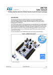
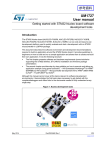
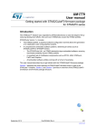
UM1726 User manual Getting started with the STM32 Nucleo board firmware package Introduction This document describes the software, firmware environment and development recommendations required to build an application around the STM32 Nucleo board (NUCLEO-F103RB, NUCLEO-L152RE, NUCLEO-F030R8 and NUCLEO-F302R8) with some demonstration firmware (STSW-STM32143). The STM32 Nucleo board is a low-cost and easy-to-use development kit to quickly evaluate and start some development with ARM® 32-bit Cortex™-M microcontrollers of the STM32 series (STM32F103, STM32F030, STM32L152 and STM32F302). Before installing and using the product, please accept the Evaluation Product License Agreement available at www.st.com/epla. This document also presents how to promptly start using STM32 Nucleo boards with mbed online tools (http://mbed.org). For more information on the STM32 Nucleo board visit www.st.com/stm32nucleo. Figure 1. STM32 Nucleo board(1) 1. Picture not contractual. April 2014 DocID025839 Rev 2 1/16 www.st.com Contents UM1726 Contents 1 Quick start . . . . . . . . . . . . . . . . . . . . . . . . . . . . . . . . . . . . . . . . . . . . . . . . . 5 1.1 Hardware requirement . . . . . . . . . . . . . . . . . . . . . . . . . . . . . . . . . . . . . . . . 5 1.2 Running the pre-loaded demonstration software . . . . . . . . . . . . . . . . . . . . 5 1.3 Example of Adafruit shield . . . . . . . . . . . . . . . . . . . . . . . . . . . . . . . . . . . . . 6 1.4 2 1.3.1 Hardware requirements . . . . . . . . . . . . . . . . . . . . . . . . . . . . . . . . . . . . . . 6 1.3.2 Loading and running the demonstration software . . . . . . . . . . . . . . . . . . 7 Quick start with mbed online tools . . . . . . . . . . . . . . . . . . . . . . . . . . . . . . . 9 Firmware package based on Standard Peripheral Library . . . . . . . . . 11 2.1 Package description . . . . . . . . . . . . . . . . . . . . . . . . . . . . . . . . . . . . . . . . . 11 2.2 Nucleo BSP . . . . . . . . . . . . . . . . . . . . . . . . . . . . . . . . . . . . . . . . . . . . . . . 12 2.3 Programming firmware application . . . . . . . . . . . . . . . . . . . . . . . . . . . . . . 12 2.3.1 IDE requirement . . . . . . . . . . . . . . . . . . . . . . . . . . . . . . . . . . . . . . . . . . . 12 2.3.2 Programming application . . . . . . . . . . . . . . . . . . . . . . . . . . . . . . . . . . . . 13 3 References . . . . . . . . . . . . . . . . . . . . . . . . . . . . . . . . . . . . . . . . . . . . . . . . 14 4 Revision history . . . . . . . . . . . . . . . . . . . . . . . . . . . . . . . . . . . . . . . . . . . 15 2/16 DocID025839 Rev 2 UM1726 List of tables List of tables Table 1. Document revision history. . . . . . . . . . . . . . . . . . . . . . . . . . . . . . . . . . . . . . . . . . . . . . . . . . 15 DocID025839 Rev 2 3/16 3 List of figures UM1726 List of figures Figure 1. Figure 2. Figure 3. Figure 4. Figure 5. Figure 6. Figure 7. Figure 8. Figure 9. 4/16 STM32 Nucleo board(1) . . . . . . . . . . . . . . . . . . . . . . . . . . . . . . . . . . . . . . . . . . . . . . . . . . . . 1 Hardware environment . . . . . . . . . . . . . . . . . . . . . . . . . . . . . . . . . . . . . . . . . . . . . . . . . . . . . 7 Opening the compiler environment . . . . . . . . . . . . . . . . . . . . . . . . . . . . . . . . . . . . . . . . . . . . 9 Selecting the STM32 Nucleo board . . . . . . . . . . . . . . . . . . . . . . . . . . . . . . . . . . . . . . . . . . . 9 Using the “Import” functionality . . . . . . . . . . . . . . . . . . . . . . . . . . . . . . . . . . . . . . . . . . . . . . . 9 Access to NUCLEO drive . . . . . . . . . . . . . . . . . . . . . . . . . . . . . . . . . . . . . . . . . . . . . . . . . . 10 Selecting and compiling your example . . . . . . . . . . . . . . . . . . . . . . . . . . . . . . . . . . . . . . . . 10 Firmware package content . . . . . . . . . . . . . . . . . . . . . . . . . . . . . . . . . . . . . . . . . . . . . . . . . 11 Nucleo BSP architecture. . . . . . . . . . . . . . . . . . . . . . . . . . . . . . . . . . . . . . . . . . . . . . . . . . . 12 DocID025839 Rev 2 UM1726 1 Quick start Quick start The STM32 Nucleo board demonstration software is already pre-loaded in the Flash memory on the STM32 Nucleo board. This demonstration implements led toggling according to user clicks on the button B1. Download the latest versions of source code and associated documentation from www.st.com/stm32nucleo. The STM32 Nucleo firmware package available at www.st.com/stm32nucleo, provides the updated version of the demonstration firmware that supports an Arduino shield sample with color TFT LCD, microSD and joystick. This shield is not provided with the STM32 Nucleo board, it has to be purchased by the user. When connecting this shield, the demonstration firmware offers additional functionality to the led toggling: Use the joystick to navigate between the images Read *.bmp images from uSD card using the FatFS file system and display them on the TFT LCD The following sections include the step-by-step description to start using STM32 Nucleo board demonstration software. 1.1 Hardware requirement The requirements to configure the Nucleo board and start with the demonstration software are as follows: One 'USB type A to Mini-B' cable to power up the STM32 Nucleo board from the USB ST-LINK (USB connector CN1) Check jumper positions on the board – JP1 OFF, – JP5 (PWR) on U5V side ON, – JP6 (IDD) ON. 1.2 Running the pre-loaded demonstration software Follow the sequence below to launch the pre-loaded demonstration application: 1. Connect the STM32 Nucleo board (connector CN1) to a PC using the USB- type-A to Mini-B cable to power the board. The red LED LD3 (PWR) and LD1 (COM) light up, The green LED LD2 blinks. 2. Press the user button B1 3. Observe how the blinking of the green LED LD2 changes according to your clicks on button B1. DocID025839 Rev 2 5/16 15 Quick start 1.3 UM1726 Example of Adafruit shield The STM32 Nucleo board supports Arduino connectivity. The shield sample may be found on the Adafruit website (reference ID 802) with the following features: one 1.8” TFT screen, one microSD card slot, one 5-way joystick navigation. Note: this shield is just an example of Arduino shield usage, you can get more details on Adafruit website. You can download the latest firmware versions source code that supports this LCD shield from www.st.com/stm32nucleo. Below, description of hardware requirement and how to start using the LCD shield and STM32 Nucleo board. 1.3.1 Hardware requirements The following hardware is required for the example of LCD shield: STM32 Nucleo board Adafruit 1.8" TFT LCD shield (reference ID: 802) USB type A to Mini-B cable to power up the STM32 Nucleo board from the USB STLINK (USB Connector CN1) In addition to gathering the hardware please follow the recommendations below. 1. Configure the STM32 Nucleo board as described in Section 1.1: Hardware requirement 2. Connect the LCD shield to the STM32 Nucleo board using the connectors CN5, CN6, CN8 and CN9 as shown in Figure 2. 6/16 DocID025839 Rev 2 UM1726 Quick start Figure 2. Hardware environment 1.3.2 Loading and running the demonstration software The provided demonstration program display.bmp images using FatFs file system from the SD Card on the TFT. There are two ways of programming the STM32 Nucleo board: Method1: upload the STM32xxx_Nucleo_Demo.hex from the firmware package available under Projects\NUCLEO-XXX\Demonstration\Binary (for example for STM32F103, the demonstration binary is named STM32F103_Nucleo_Demo.hex and located under Projects\ NUCLEO-F103RB \Demonstration\Binary). Method 2: program the demonstration software as explained in Section 2.3.2: Programming application. Follow the sequence written hereafter to discover the demonstration: DocID025839 Rev 2 7/16 15 Quick start UM1726 1. 2. 3. The demonstration starts by checking the availability of Adafruit 1.8" TFT shield on top of the STM32 Nucleo board. This is done by reading the state of the IO PB.00 pin which is mapped to the Joystick available on Adafruit 1.8" TFT shield. If the state of PB.00 is high it means that the Adafruit 1.8" TFT shield is available. Adafruit 1.8" TFT shield is not available: LED2 remains toggling with a first frequency equal to ~1Hz. Press the USER button so LED2 toggles with a second frequency equal to ~5Hz then press again the USER button, and LED2 will toggle with 10Hz frequency. This is done in an infinite loop. Adafruit 1.8" TFT shield is available: SD Card not available: a message is displayed on the TFT indicating that an SD Card is missing. Insert an SD Card and reset the STM32 Nucleo board. SD Card available: a menu is displayed on the TFT. Follow the instructions given below: a) Press the JoyStick DOWN to keep the menu display. b) Choose the desired display mode: press the Joystick DOWN for automatic mode or press the JoyStick UP for manual mode. c) If the manual mode is selected, press the JoyStick RIGHT to display the next image or press the JoyStick LEFT to display the previous image. Press JoyStick SEL to switch the display mode automatically. If the SD Card is unplugged during this mode, a message indicating that the SD Card is missing is displayed on the first attempt to display the next or the previous image. d) If the automatic mode is selected, the images available on the SD Card are displayed sequentially in a forever loop. To switch to manual mode apply a long press (~1s) on JoyStick SEL. If the SD Card is unplugged during this mode, a message indicating its absence is displayed on the first attempt to display next image. e) If the SD Card is not FAT formatted, a message is displayed on the TFT indicating that the formatting of the SD Card is necessary. f) If the content of the SD Card is other than a bitmap file, a message is displayed on the TFT mentioning that it is not supported. In this case, format the SD Card and upload some .bmp files with the following criteria: Dimensions: 128x160 pixels Width: 128 pixels Height: 160 pixels Bit depth:16 Item type: BMP file The name of the bmp image file must not exceed 11 characters (including the .bmp extension) and all files must be stored under the root of the uSD. Note: 8/16 Ready to use .bmp files are available within the firmware package under the “Projects\NUCLEO-XXX\Demonstration\Media” folder. DocID025839 Rev 2 UM1726 1.4 Quick start Quick start with mbed online tools Access to the mbed on-line online tools at http://mbed.org. Create your account by clicking on signup. Once your account is created, open the compiler environment page by clicking on Compiler (Figure 3). Figure 3. Opening the compiler environment Select the STM32 Nucleo board of interest (Figure 4). Figure 4. Selecting the STM32 Nucleo board Click on Import and type “nucleo” in the search filter (Figure 5). Figure 5. Using the “Import” functionality Import the example of your choice in your workspace. Note: You can also go on the STM32 Nucleo board web page and import any example from this page. Plug-in the STM32 Nucleo board to the PC through the USB cable. You must see the NUCLEO drive (Figure 6). DocID025839 Rev 2 9/16 15 Quick start UM1726 Figure 6. Access to NUCLEO drive Select and compile your example (Figure 7). Figure 7. Selecting and compiling your example When the compilation has ended, a window pops up asking to save the generated binary file. Save the binary file on the NUCLEO drive. The binary file is programmed into the MCU flash memory and the Nucleo board is automatically reset. Your program is running. You can now create and share your own examples with others. 10/16 DocID025839 Rev 2 UM1726 2 Firmware package based on Standard Peripheral Library Firmware package based on Standard Peripheral Library To start with the STM32 Nucleo board, we recommend that you use the firmware package that contains a set of IP examples and demonstration available at www.st.com/stm32nucleo. 2.1 Package description The STM32 Nucleo board firmware drivers and examples are based on the Standard Peripheral library, and are provided in one single package supplied in a zip file. The extraction of the zip file generates one folder, STM32_Nucleo_FW_VX.Y.Z that contains the sub folders shown in Figure 8. You can run the examples provided within this package (four examples are ready to be run). Figure 8. Firmware package content DocID025839 Rev 2 11/16 15 Firmware package based on Standard Peripheral Library 2.2 UM1726 Nucleo BSP The Nucleo BSP architecture driver supports three devices; the stm32f1xx, stm32f0xx and stm32l1xx. For each device, a set of Button, Led and Joystick drivers is stored in separate folders. The Adafruit folder includes the LCD and uSD driver of the Adafruit shield. These two drivers are common for all devices. The SPI interface is used to drive the LCD and uSD card available on the Adafruit 1.8" TFT shield. Figure 9. Nucleo BSP architecture 2.3 Programming firmware application 2.3.1 IDE requirement Please proceed as follows to start programming: 1. Install the preferred Integrated Development Environment (IDE). 2. Install the ST-LINK/V2.1 driver available on ST website. Note: 12/16 the required information to download and install the desired IDE and ST-LINK/V2.1 is detailed in UM1727 - User manual - Getting started with STM32 Nucleo board software development tools. DocID025839 Rev 2 UM1726 2.3.2 Firmware package based on Standard Peripheral Library Programming application Four IP examples are provided with the firmware package (Figure 8) under STM32_Nucleo_FW_VX.Y.Z\Projects\ Use one of two supported tool chains to program the application on the STM32 Nucleo board. To program the demonstration application, follow the steps below: 1. Open the application folder Projects\NUCLEO-XXX\Demonstration\ 2. Chose the desired IDE project (EWARM for IAR, MDK-ARM for Keil and TrueSTUDIO for Attolic) 3. Double click on the project file (for example STM32xxx_Nucleo_Demo.eww for EWARM) 4. Rebuild all files: Go to Project and select Rebuild all 5. Load the project image: Go to Project- and select Debug 6. Run the program: Go to Debug and select Go The demonstration software as well as other software examples that allow you to discover the STM32 microcontroller features are available on ST website at www.st.com/stm32nucleo. DocID025839 Rev 2 13/16 15 References 3 UM1726 References 1. STM32F103x8 STM32F103xB datasheet - Medium-density performance line ARMbased 32-bit MCU with 64 or 128 KB Flash, USB, CAN, 7 timers, 2 ADCs, 9 com. interfaces 2. STM32L151xE and STM32L152xE datasheet - Ultra-low-power 32-bit MCU ARMbased Cortex-M3 with 512KB Flash, 80KB SRAM, 16KB EEPROM, LCD, USB, ADC, DAC 3. STM32F030x4 STM32F030x6 STM32F030x8 datasheet - Value-line ARM-based 32-bit MCU with 16 to 64-KB Flash, timers, ADC, communication interfaces, 2.4-3.6 V operation 4. RM0091 - Reference manual - STM32F0x1/STM32F0x2/STM32F0x8 advanced ARMbased 32-bit MCUs 5. RM0008 - Reference manual - STM32F101xx, STM32F102xx, STM32F103xx, STM32F105xx and STM32F107xx advanced ARM-based 32-bit MCUs 6. RM0038 - Reference manual - STM32L100xx, STM32L151xx, STM32L152xx and STM32L162xx advanced ARM-based 32-bit MCUs 7. UM1724 - User manual - STM32 Nucleo board 8. UM1727 - User manual - Getting started with STM32 Nucleo board software development tools ® ® STM32F302x4 STM32F302x6 STM32F302x8 datasheet- ARM -Cortex -M4 32b MCU+FPU, up to 64KB Flash, ADC, DAC, timers, I2C, USART, SPI/I2S, USB, CAN, COMP, PGA, 2.0 - 3.6 V 9. 10. RM0365 - Reference manual - STM32F302xx advanced ARM-based 32-bit MCUs 14/16 DocID025839 Rev 2 UM1726 4 Revision history Revision history Table 1. Document revision history Date Revision 13-Feb-2014 1 Initial release. 2 Replaced Figure 1: STM32 Nucleo board(1). Extended the applicability to NUCLEO-F302R8. Added the note in Section 2.3.1: IDE requirement. Updated: – the item 2. in Section 2.3.2: Programming application, – Figure 8: Firmware package content, – Figure 9: Nucleo BSP architecture, – Chapter 3: References. 09-Apr-2014 Changes DocID025839 Rev 2 15/16 15 UM1726 Please Read Carefully: Information in this document is provided solely in connection with ST products. STMicroelectronics NV and its subsidiaries (“ST”) reserve the right to make changes, corrections, modifications or improvements, to this document, and the products and services described herein at any time, without notice. All ST products are sold pursuant to ST’s terms and conditions of sale. Purchasers are solely responsible for the choice, selection and use of the ST products and services described herein, and ST assumes no liability whatsoever relating to the choice, selection or use of the ST products and services described herein. No license, express or implied, by estoppel or otherwise, to any intellectual property rights is granted under this document. If any part of this document refers to any third party products or services it shall not be deemed a license grant by ST for the use of such third party products or services, or any intellectual property contained therein or considered as a warranty covering the use in any manner whatsoever of such third party products or services or any intellectual property contained therein. UNLESS OTHERWISE SET FORTH IN ST’S TERMS AND CONDITIONS OF SALE ST DISCLAIMS ANY EXPRESS OR IMPLIED WARRANTY WITH RESPECT TO THE USE AND/OR SALE OF ST PRODUCTS INCLUDING WITHOUT LIMITATION IMPLIED WARRANTIES OF MERCHANTABILITY, FITNESS FOR A PARTICULAR PURPOSE (AND THEIR EQUIVALENTS UNDER THE LAWS OF ANY JURISDICTION), OR INFRINGEMENT OF ANY PATENT, COPYRIGHT OR OTHER INTELLECTUAL PROPERTY RIGHT. ST PRODUCTS ARE NOT DESIGNED OR AUTHORIZED FOR USE IN: (A) SAFETY CRITICAL APPLICATIONS SUCH AS LIFE SUPPORTING, ACTIVE IMPLANTED DEVICES OR SYSTEMS WITH PRODUCT FUNCTIONAL SAFETY REQUIREMENTS; (B) AERONAUTIC APPLICATIONS; (C) AUTOMOTIVE APPLICATIONS OR ENVIRONMENTS, AND/OR (D) AEROSPACE APPLICATIONS OR ENVIRONMENTS. WHERE ST PRODUCTS ARE NOT DESIGNED FOR SUCH USE, THE PURCHASER SHALL USE PRODUCTS AT PURCHASER’S SOLE RISK, EVEN IF ST HAS BEEN INFORMED IN WRITING OF SUCH USAGE, UNLESS A PRODUCT IS EXPRESSLY DESIGNATED BY ST AS BEING INTENDED FOR “AUTOMOTIVE, AUTOMOTIVE SAFETY OR MEDICAL” INDUSTRY DOMAINS ACCORDING TO ST PRODUCT DESIGN SPECIFICATIONS. PRODUCTS FORMALLY ESCC, QML OR JAN QUALIFIED ARE DEEMED SUITABLE FOR USE IN AEROSPACE BY THE CORRESPONDING GOVERNMENTAL AGENCY. Resale of ST products with provisions different from the statements and/or technical features set forth in this document shall immediately void any warranty granted by ST for the ST product or service described herein and shall not create or extend in any manner whatsoever, any liability of ST. ST and the ST logo are trademarks or registered trademarks of ST in various countries. Information in this document supersedes and replaces all information previously supplied. The ST logo is a registered trademark of STMicroelectronics. All other names are the property of their respective owners. © 2014 STMicroelectronics - All rights reserved STMicroelectronics group of companies Australia - Belgium - Brazil - Canada - China - Czech Republic - Finland - France - Germany - Hong Kong - India - Israel - Italy - Japan Malaysia - Malta - Morocco - Philippines - Singapore - Spain - Sweden - Switzerland - United Kingdom - United States of America www.st.com 16/16 DocID025839 Rev 2