1
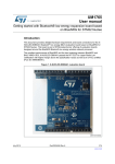
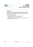
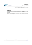
UM1765
User manual
X-NUCLEO-IDB04A1 Bluetooth low energy expansion board
based on BlueNRG for STM32 Nucleo
Introduction
This document provides detailed hardware requirements and board connections for the XNUCLEO-IDB04A1 Bluetooth® low energy (BLE) evaluation board based on BlueNRG for
STM32 Nucleo. This board is part of STMicroelectronics’ offering of evaluation boards
designed around the BlueNRG Bluetooth low energy wireless network processor.
Figure 1. X-NUCLEO-IDB04A1 evaluation board
Other BlueNRG evaluation boards are available in the following kits:
• STEVAL-IDB002V1: BlueNRG development platform
• STEVAL-IDB003V1: BlueNRG USB dongle
May 2014
DocID026346 Rev 1
1/13
www.st.com
Contents
UM1765
Contents
1
2
Getting started . . . . . . . . . . . . . . . . . . . . . . . . . . . . . . . . . . . . . . . . . . . . . . 3
1.1
Hardware requirements . . . . . . . . . . . . . . . . . . . . . . . . . . . . . . . . . . . . . . . 3
1.2
System requirements . . . . . . . . . . . . . . . . . . . . . . . . . . . . . . . . . . . . . . . . . 4
Hardware description . . . . . . . . . . . . . . . . . . . . . . . . . . . . . . . . . . . . . . . . 5
2.1
X-NUCLEO-IDB04A1 board . . . . . . . . . . . . . . . . . . . . . . . . . . . . . . . . . . . . 5
2.1.1
Current measurements . . . . . . . . . . . . . . . . . . . . . . . . . . . . . . . . . . . . . . 6
3
List of acronyms . . . . . . . . . . . . . . . . . . . . . . . . . . . . . . . . . . . . . . . . . . . . 7
4
Board schematic and bill of material . . . . . . . . . . . . . . . . . . . . . . . . . . . . 8
5
Revision history . . . . . . . . . . . . . . . . . . . . . . . . . . . . . . . . . . . . . . . . . . . 12
2/13
DocID026346 Rev 1
UM1765
1
Getting started
Getting started
This section describes the hardware requirements for the X-NUCLEO-IDB04A1 evaluation
board.
1.1
Hardware requirements
The X-NUCLEO-IDB04A1 is an expansion board for use with STM32 Nucleo boards (please
refer to UM1724 on www.st.com for further information). To function correctly, the STM32
Nucleo board must be connected to the X-NUCLEO-IDB04A1 board as shown in Figure 2
below.
Figure 2. X-NUCLEO-IDB04A1 connected to STM32 Nucleo board
The interconnection between the STM32 Nucleo and the X-NUCLEO-IDB04A1 has been
designed to permit the use of any STM32 Nucleo board, although the optimal combination is
obtained using the NUCLEO-L152RE or NUCLEO-L053R8 hosting the ultra-low power
STM32.
DocID026346 Rev 1
3/13
13
Getting started
1.2
UM1765
System requirements
Using the Nucleo boards with the X-NUCLEO-IDB04A1 expansion board requires the
following software and hardware:
•
a Windows PC (XP, Vista, 7, 8) to install the software package
•
a USB type A to Mini-B USB cable to connect the Nucleo to the PC
Installation of the board firmware package (order code: STSW-IDB04V1) and the BlueNRG
graphical user interface utility on the user’s PC requires the following:
•
At least 128 MB of RAM
•
40 MB of hard disk space available
The STSW-IDB04A1 firmware and related documentation is available on st.com at
http://www.st.com/web/en/catalog/tools/FM116/SC1075/PF260517.
4/13
DocID026346 Rev 1
UM1765
Hardware description
2
Hardware description
This section describes the X-NUCLEO-IDB04A1 features and provides information which
could be useful for understanding the board schematics.
2.1
X-NUCLEO-IDB04A1 board
The board allows the user to test the functionality of the BlueNRG processor. It hosts the
innovative BALF-NRG-01D3 balun & harmonic filter and its functionality can be exploited
using the firmware package contained in the STSW-IDB04V1. It is fundamental to program
the microcontroller on the STM32 Nucleo board. Please refer to user manuals UM1724 and
UM1725, available on www.st.com.
The BlueNRG processor and the STM32 Nucleo board are connected through connectors
CN5, CN6, CN8 and CN9 (see Table 1 for details). The pins indicated with an asterisk (*)
represent an alternative pin for that specific function, i.e. SPI_IRQ could be moved from
CN8.1 to CN5.2.
A0
A1
A2
A3
A4
A5
VIN
GND
GND
5V
3V3
RESET
IOREF
NC
Table 1. Interconnection between STM32 Nucleo board and X-NUCLEO-IDB04A1
1
2
3
4
5
6
D0
D1
D2
D3
SPI_CSN
D5
D4
SPI_IRQ
D7
D6
8
D8
D12
D14
D15
7
GND
D13
6
D9
GND
5
GND
4
D10
3
D11
2
3V3
1
AREF
Left connectors
Right connectors
3
2
1
8
BNRG_RST
4
SPI_MCSN
5
SPI_IRQ*
6
SPI_MOSI
7
SPI_MISO
8
SPI_CLK*
9
GND
10
CN9 digital
7
6
5
4
3
2
1
SPI_CLK
CN5 digital
To change the default pin SPI_CLK and SPI_IRQ, the user must disassemble, respectively,
R10 and R12, and assemble R11 and R16.
DocID026346 Rev 1
5/13
13
Hardware description
UM1765
The board also includes:
–
a high frequency 16 MHz crystal
–
a low frequency 32 kHz crystal for lowest power consumption
–
a BALF-NRG-01D3 balun & harmonic filter
–
an EEPROM M95640 to store the board parameters
Not mounted:
2.1.1
–
a JTAG connector to program the BlueNRG processor
–
an SMA connector for the external antenna
Current measurements
To monitor the power consumption of entire BlueNRG X-NUCLEO-IDB04A1 board, jumper
U5 can be used, inserting an ammeter probe between pins 1 and 2 of the connector. Since
the power consumption of BlueNRG during most of its operating time is very low, an
accurate instrument in the range of few microamps may be required.
6/13
DocID026346 Rev 1
UM1765
3
List of acronyms
List of acronyms
Table 2. List of acronyms used in the document
Term
Meaning
BLE
Bluetooth low energy
USB
Universal serial bus
DocID026346 Rev 1
7/13
13
Board schematic and bill of material
4
UM1765
Board schematic and bill of material
Table 3. Bill of materials (part 1)
Item
Quantity
1
4
C1, C17, C20, C22
2
6
C2, C16, C18, C19, C21, C23 100n_0402_X7R
VBAT filtering
3
2
C3, C15
100p_0402_C0G
VBAT filtering
4
1
C4
150n_0402_X5R
VREG filtering
5
2
C5, C6
22p_0402_C0G
32 kHz XTAL load cap
6
1
C27
56p_0402_C0G
TX/RX balun cap
7
1
C24
56p_0402_C0G
TX/RX bypass cap
8
1
C25
TBD_0402_COG
Tuning cap
9
1
C26
TBD_0402_COG
Tuning cap
10
1
L4
TBD_0402
Tuning cap
11
2
C13, C14
15p_0402_C0G
16 MHz XTAL load cap
12
1
D1
Soldered between pins 1
and 2
SMPS out inductor
13
1
JP1
HEADER 1X3
Male strip 1X3, 100 mils
14
1
J1
THR 1.27 mm 2x5 pins
Test connector
15
1
J2
RF_IN/OUT
UFL jack assembly, End Launch
16
1
U4
BALF-NRG-01D3
Integrated balun for BlueNRG
QFN32
17
1
CN5
Extra-long 10 pins
female-male strip
Female side mounted to the top
18
2
CN6, CN9
Extra-long 8 pins femalemale strip
Female side mounted to the top
CN8
Extra-long 6 pins femalemale strip
Female side mounted to the top
19
Reference
Part
1u_0402_X5R
Note
VBAT & SMPS OUT filter cap
20
1
Q1
XTAL
XTAL
21
1
Q2
XTAL
XTAL
8/13
DocID026346 Rev 1
UM1765
Board schematic and bill of material
Table 3. Bill of materials (part 1) (continued)
Item
Quantity
Reference
Part
Note
22
5
R1, R3, R4, R5, R6
23
1
R2
10k_0402
Connect to ground
24
2
R7, R9
100k_0402
Pull-up and pull-down
25
4
R10, R12, R14, R15
0_0402
jumper-resistor
26
3
R11, R13, R16
0_0402
jumper-resistor
27
1
U1
BlueNRG
RF IC
28
1
U5
HEADER 1X2
Male strip 1X2, 100 mils
27
1
U3
EEPROM
Memory
28
3
TEST8, TEST11,TEST12
Test point
Test point
Connect to VDD, pull-down
Table 4. Bill of materials (part 2)
Item
Package
Manufacturer
Manufacturer’s ordering code /
orderable part number
+8 dBm
1
SM/C_0402
Murata
GRM155R61A105KE15
1 uF
2
SM/C_0402
Murata
GRM155R71C104KA88
100 nF
3
SM/C_0402
Murata
GRM1555C1H101JZ01
100 pF
4
SM/C_0402
Murata
GRM155R61A154KE19
150 nF
5
SM/C_0402
Murata
GRM1555C1H220JZ01
22 pF
6
SM/C_0402
Murata
GRM1555C1H560JA01
56 pF
7
SM/C_0402
Murata
8
SM/C_0402
Murata
9
SM/C_0402
10
SM/C_0402
Murata
GRM1555C1H180JZ01
1.8 pF
11
SM/C_0402
Murata
GRM1555C1H150JZ01
15 pF
12
SM/L_0805
Murata
LQM21FN100M70L
10 uH
13
WALCON.100/VH/TM2
OE/W.325/10/MOD
SAMTEC
FTSH-105-01-F-D-K
NE
14
NE
GRM1555C1H120JZ01
1.2 pF
NE
DocID026346 Rev 1
9/13
13
Board schematic and bill of material
UM1765
Table 4. Bill of materials (part 2) (continued)
Item
15
Package
SMT
16
Manufacturer
Manufacturer’s ordering code /
orderable part number
Hirose
U.FL-R-SMT-1(10) Digikey
H11891CT-ND
STMicroelectronics
BALF-NRG-01D3
+8 dBm
NE
17
2.54 mm pitch
4UCON
18688
18
2.54 mm pitch
4UCON
18688
19
2.54 mm pitch
4UCON
18688
20
NX3215SA
NDK
NX3215SA-32.768kHz-EXS00AMU00003
32.768 kHz
21
XTAL_32_25_REV2
NDK
NX3225SA -16.000MHz-EXS00ACS05997
16 MHz
22
SM/R_0402
Tyco Electronics
NE
23
SM/R_0402
Tyco Electronics
10 k
24
SM/R_0402
Tyco Electronics
100 k
25
SM/R_0402
Tyco Electronics
0 Ohm
26
SM/R_0402
Tyco Electronics
NE
27
QFN32
STMicroelectronics
28
WALCON.100/VH/TM2
OE/W.325/10/MOD
27
SO8N
28
TP
10/13
STMicroelectronics
M95640-RMN6
NE
DocID026346 Rev 1
100k_0402
R7
CON6
CN8
CON8
CN6
nS
MISO
1
2
3
4
5
6
1
2
3
4
5
6
7
8
R3
nc
1
2
3
4
R12
0
3V3
R4
nc
2
IRQ
CSN
U5
1
R15
M95640
Vcc
nS
Q nHOLD
C
nW
D
Vss
U3
0
1
Jumper2
R5
nc
8
7
6
5
1
3
5
7
9
R11
0
CLK
MOSI
0
R13
Test connector
Not mounted
2
VDD
R6
nc
0
R16
8
7
6
5
4
3
2
1
CON8
CN9
C3
C17
VDD
1u_0402_X5R
C20
U1
VBAT2
VBAT1
MOSI 1
CLK 2
3
IRQ
4
VBAT3 5
6
7
TEST4 8
VDD
C1
1u_0402_X5R
100p_0402_COG
1u_0402_X5R
CON10
CN5
C19
100n_0402_X7R
0
R10
0
R14
10
9
8
7
6
5
4
3
2
1
VDD
MISO
MOSI
RST
Not mounted
R9
100k_0402
3V3
CLK
Not mounted
33
150n_0402_X5R
C4
C2
C15
100n_0402_X7R
C21
100n_0402_X7R
C18
100p_0402_COG
1
D1
C5
VDD
24
23
22
21
20
19
18
17
HIGH-FREQ-XTAL
1u_0402_X5R
C22
VDD
VBAT3
Q2
VBAT2
100n_0402_X7R
C23
C16
100n_0402_X7R
C13
12p_0402_COG
VBAT1
SXTAL0
SXTAL1
RF0
RF1
VBAT2
FXTAL0
FXTAL1
XTAL_32k
Q1
U4
A1
A2
1
2
BALF-NRG-01D3
B1
B2
TEST12
TEST11
TEST8
TEST12
TEST11
TEST8
12p_0402_COG
C14
4
3
22p_0402_COG
C6
Solder a 10u_0805 between 1-2
or a 0R0_0805 between 1-3
22p_0402_COG
3
100n_0402_X7R
SPI_MOSI
SPI_CLK
SPI_IRQ
BlueNRG-N
TEST1
VBAT3
TEST2
TEST3
TEST4
GND
J1
CLK
CSN
2
2
4
6
8
10
IRQ
VBAT1
Male Connector 2x5
TEST5
TEST6
TEST7
56p
C27
1
56p
GND
NO_SMPS
10k_0402
R2
C25
1
TEST10
3
TEST10 VDD
JP1
C26
TBD_0402_COG
TBD_0402
L4
PCB Meander Antenna
3
TBD_0402_COG
C24
nc
R1
U.FL connector
GND
J2
VDD
SIG
2
TEST5
TEST4
TEST6
TEST7
TEST8
nS
32
MISO
31
CSN
30
TEST10
29
28
27 NO_SMPS
26
25
RST
SPI_MISO
SPI_CS
TEST10
VDD1V2
SMPSFILT2
NO_SMPS
SMPSFILT1
RESETN
TEST5
TEST6
TEST7
VDD1V8
TEST8
TEST9
TEST11
TEST12
9
10
11
12
13
14
15
16
TEST11
TEST12
DocID026346 Rev 1
2
UM1765
Board schematic and bill of material
Figure 3. X-NUCLEO-IDB04A1 expansion board schematic diagram
11/13
13
Revision history
5
UM1765
Revision history
Table 5. Document revision history
12/13
Date
Revision
16-May-2014
1
Changes
Initial release.
DocID026346 Rev 1
UM1765
Please Read Carefully:
Information in this document is provided solely in connection with ST products. STMicroelectronics NV and its subsidiaries (“ST”) reserve the
right to make changes, corrections, modifications or improvements, to this document, and the products and services described herein at any
time, without notice.
All ST products are sold pursuant to ST’s terms and conditions of sale.
Purchasers are solely responsible for the choice, selection and use of the ST products and services described herein, and ST assumes no
liability whatsoever relating to the choice, selection or use of the ST products and services described herein.
No license, express or implied, by estoppel or otherwise, to any intellectual property rights is granted under this document. If any part of this
document refers to any third party products or services it shall not be deemed a license grant by ST for the use of such third party products
or services, or any intellectual property contained therein or considered as a warranty covering the use in any manner whatsoever of such
third party products or services or any intellectual property contained therein.
UNLESS OTHERWISE SET FORTH IN ST’S TERMS AND CONDITIONS OF SALE ST DISCLAIMS ANY EXPRESS OR IMPLIED
WARRANTY WITH RESPECT TO THE USE AND/OR SALE OF ST PRODUCTS INCLUDING WITHOUT LIMITATION IMPLIED
WARRANTIES OF MERCHANTABILITY, FITNESS FOR A PARTICULAR PURPOSE (AND THEIR EQUIVALENTS UNDER THE LAWS
OF ANY JURISDICTION), OR INFRINGEMENT OF ANY PATENT, COPYRIGHT OR OTHER INTELLECTUAL PROPERTY RIGHT.
ST PRODUCTS ARE NOT DESIGNED OR AUTHORIZED FOR USE IN: (A) SAFETY CRITICAL APPLICATIONS SUCH AS LIFE
SUPPORTING, ACTIVE IMPLANTED DEVICES OR SYSTEMS WITH PRODUCT FUNCTIONAL SAFETY REQUIREMENTS; (B)
AERONAUTIC APPLICATIONS; (C) AUTOMOTIVE APPLICATIONS OR ENVIRONMENTS, AND/OR (D) AEROSPACE APPLICATIONS
OR ENVIRONMENTS. WHERE ST PRODUCTS ARE NOT DESIGNED FOR SUCH USE, THE PURCHASER SHALL USE PRODUCTS AT
PURCHASER’S SOLE RISK, EVEN IF ST HAS BEEN INFORMED IN WRITING OF SUCH USAGE, UNLESS A PRODUCT IS
EXPRESSLY DESIGNATED BY ST AS BEING INTENDED FOR “AUTOMOTIVE, AUTOMOTIVE SAFETY OR MEDICAL” INDUSTRY
DOMAINS ACCORDING TO ST PRODUCT DESIGN SPECIFICATIONS. PRODUCTS FORMALLY ESCC, QML OR JAN QUALIFIED ARE
DEEMED SUITABLE FOR USE IN AEROSPACE BY THE CORRESPONDING GOVERNMENTAL AGENCY.
Resale of ST products with provisions different from the statements and/or technical features set forth in this document shall immediately void
any warranty granted by ST for the ST product or service described herein and shall not create or extend in any manner whatsoever, any
liability of ST.
ST and the ST logo are trademarks or registered trademarks of ST in various countries.
Information in this document supersedes and replaces all information previously supplied.
The ST logo is a registered trademark of STMicroelectronics. All other names are the property of their respective owners.
© 2014 STMicroelectronics - All rights reserved
STMicroelectronics group of companies
Australia - Belgium - Brazil - Canada - China - Czech Republic - Finland - France - Germany - Hong Kong - India - Israel - Italy - Japan Malaysia - Malta - Morocco - Philippines - Singapore - Spain - Sweden - Switzerland - United Kingdom - United States of America
www.st.com
DocID026346 Rev 1
13/13
13