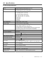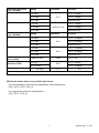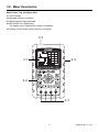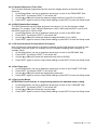
1
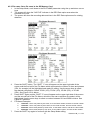
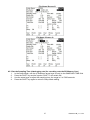
User Guide 3-Phase Power and Harmonics Analyzer / Datalogger MODEL PQ3470 Table of Contents 1.0 INTRODUCTION 1-1 Features.................................................................................................. 3 1-2 Safety ....................................................................................................... 4 2.0 SPECIFICATIONS 2-1 General Specifications ................................................................................. 5 2-2 Electrical Specifications .................................................................................... 6 3.0 METER DESCRIPTION ............................................................. .8 4.0 METER BASICS AND THE SETUP MODE 4-1 Initialization Screen ...................................................................................................... 10 4-2 Measurement Screen Example .......................................................................... 10 4-3 Keypad Summary ................................................................................................. 11 4-4 Setup Mode Basics ...................................................................................................... 12 4-5 Setup Mode In Detail......................................................................................... 14 5.0 POWER MEASUREMENT PROCEDURES 5-1 1Φ 2W (single phase two wire) measurement .......................................... .21 5-2 1Φ 3W (single phase three wire) measurement ........................................ .22 5-3 3Φ 3W (three phase three wire) measurement ......................................... .23 5-4 3Φ 4W (three phase four wire) measurement ........................................... .24 5-5 CT and PT measurement .......................................................................................... .25 5-6 Zero Adjust for Watt Hour Measurement ................................................................ .26 5-7 Harmonics function Measurement ........................................................................... .26 5-8 Graphic Phasor Measurement ................................................................................. .28 5-9 Voltage / Current Waveform...................................................................................... .29 5-10 Transient Capture (Dips, Swells, Outage) ............................................................ .30 5-11 Data Logger ..................................................................................................................... 31 5-12 Data Hold ......................................................................................................32 5-13 Display Backlight key....................................................................................32 5-14 LOWBAT (Low Battery) screen ...................................................................32 5-15 Measurement Definitions .................................................................................. .33 5-16 Reset Button....................................................................................................... .33 6.0 MAINTENANCE 6-1 Cleaning ................................................................................................................. 34 6-2 Battery Replacement............................................................................................ 34 7.0 SD Card 7-1 Download Data from SD Card ......................................................... 35 2 PQ3470-en-GB_V1.7 6/15 1.0 Introduction Congratulations on your purchase of the Model PQ3470 Power Analyzer. This instrument is fully tested and calibrated prior to delivery; proper use and care of this meter will provide years of reliable service. 1.1 Features Large dot-matrix, numerical, backlit LCD Full system analysis with up to 35 parameters: o Voltage (phase-to-phase) and Voltage (phase-to-ground) o Current (Amps) phase-to-ground o KW / KVA / KVAR / PF (phase) o KW / KVA / KVAR / PF (system) o KWH / KVAH / KVARH / PFH (system) o Phase angle o Harmonics 600.0VAC input with CAT III-600V safety rating Adjustable Current Transformer (CT) and Potential Transformer (PT) ratio for high power distribution systems Log up to 30,000 reading on removable SD memory card in Excel® format Wide sampling rate range (from 2 seconds up to 2 hours) TM Captured measurements imported directly into Excel via SD memory card Easy-to-use onscreen menu Easy-to-hold rugged over-molded housing 3 PQ3470-en-GB_V1.7 6/15 1.2 Safety CAUTION: Risk of electric shock. Do not attempt to open or disassemble the meter while taking measurements CAUTION: Do not attempt to measure Voltage or Current that exceeds specified limits Do not operate this instrument in wet or dusty environments. Do not operate this instrument in the presence of combustible or explosive gas Do not touch exposed metal parts or unused terminals. Consider the use of rubber gloves in operation. Do not operate in excess of AC 500V (Phase to Neutral), or AC 600V (Phase to Phase) Do not operate this instrument if it appears to be malfunctioning Remove the test leads from the meter before opening the battery compartment cover When cleaning, use only a dry cloth to wipe the meter housing. Do not use liquids of any kind to clean the meter Safety Symbols: CAUTION DOUBLE INSULATION RISK OF ELECTRIC SHOCK Environmental Conditions Installation Category III 600V Pollution Degree 2 Altitude limit: 2000m Indoor use only Relative Humidity maximum: 80% 4 PQ3470-en-GB_V1.7 6/15 2.0 Specifications 2.1 General Specifications Circuit Custom single-chip microprocessor LSI circuit Display LCD Size: 81.4 X 61 mm (3.2 X 2.4”) Dot Matrix backlit LCD (320 X 240 pixels) Measurements V (voltage phase to phase) V (voltage phase to ground) A (Current Phase to ground) KW / KVA/ KVAR / PF (Phase) KW / KVA/ KVAR / PF (System) Power factor Phase angle Frequency Harmonics Wire configurations 1P/2W, 1P/3W, 3P/3W, 3P/4W Voltage ranges 10 ACV to 600 ACV (Auto Range) Current ranges Current probe input signal voltage (ACV): 200mV /300mV /500mV /1V /2V /3V Current probe input current range (ACA): 20A/200A/2000A (1200A)/30A/300A/3000A/60A/600A/6000A Note that the meter has universal probe compatibility Safety standard IEC1010 CAT III 600 V ACV input impedance 10M ohms Range select ACV Auto Range ACA Manual Range Clamp frequency response 40 Hz to 1 KHz Tested clamp frequency 45 to 65 Hz Over-load protection ACV Over-range "OL" is displayed; ACV Data on SD card will read ‘9999’ or ‘999’ for over-range data Under-range "UR" is displayed Data Hold Freezes displayed reading Data Recording SD memory card SD Card capacity 2G SD max. / 16G SDHC max. Sampling Time Approx. 1 second (LCD) / 2000 samples per period 720 ACV RMS 5 PQ3470-en-GB_V1.7 6/15 Real time data logger saves data to SD memory card for download to PC (data files open directly to spreadsheet) Datalogger Sampling rate: From 2 seconds to 7200 seconds Max. file capacity: 30,000 records Data Output Serial or USB connection (cable supplied) Operating Temperature 0 to 50 C (32 to 122 F) Operating Relative Humidity 80% Relative Humidity max. Power Supply Eight (8) ‘AA’ 1.5VDC batteries or AC 9V power adapter Power Consumption Meter: 270 mA DC; Clamp: 22 mA DC Max. Conductor size Clamp can accommodate up to 50 mm (2.0”) diameter Weight Meter: 1026g (2.3 lbs.) (with batteries); Clamp: 467g (1.0lbs) Dimensions o o Meter: 225 X 125 X 64 mm (8.86 X 4.92 X 2.52“) Optional Clamp: 210 X 64 X 33mm (8.3 X 2.5 X 1.3”) Optional Clamp Jaw: 86 mm (3.4”) Outer diameter Accessories Included Instruction manual Batteries SD card (2G) 2.1 Electrical Specifications (45 to 65Hz; 23±5°C) Function Range Resolution Accuracy* AC Voltage 10.0V to 600.0V 0.1V ± (0.5% range + 3 digits) AC Voltage (peak to peak) 28.2V to 1.697kV 0.1V to 1V ± (0.5% range + 30 digits) AC Current (trms) 0.2A to 6000A 0.001A to 1 A ± (0.5% range + 5 digits) AC Current (peak to peak) 2.828A to 16.97kA 0.001A to 10 A ± (0.5% range + 30 digits) Power Factor 0.00 to 1.00 0.01 ± 0.04 Φ Phase Angle -180° to 180° 0.1° ± 1° 45 to 65Hz 0.1Hz 0.1Hz 0.001k to 0.001M ± (1% range+8 digits) 0.001k to 0.001M ± (1% range+8 digits) Frequency Power 0.0 to 3.6MW 0.0 to 3.6MVA 0.0 to 3.6MVAR Watt-Hour 0.0 to 3.6MWH 0.0 to 3.6MVAH 0.0 to 3.6MVARH *Meter accuracy only. For system accuracy add the accuracy of the clamp used. 6 PQ3470-en-GB_V1.7 6/15 Harmonics Magnitude (>5%, 50/60Hz) ACV Range Resolution 1 to 20th ± (2% + 5 digits) 0.1V 21 to 30th ACA Reference only 1 to 20th ± (2% + 5 digits)* 0.001A to 1A 31 to 50th Range Resolution 1 to 20th 0.1% ± (4% + 20 digits) 31 to 50th Reference only 1 to 20th ± (2% + 10 digits)* 0.1% 31 to 50th Phase angle Accuracy ± (2% + 10 digits) 21 to 30th Crest Factor (CFV or CFA) Total Harmonic Distortion (THD) ± (4% + 5 digits)* Reference only 21 to 30th ACA ± (4% + 5 digits) 31 to 50th 21 to 30th Harmonics Magnitude (>5%, 50/60Hz) ACV Accuracy ± (4% + 20 digits)* Reference only 1.000 to 9.999 0.001 0 to 20% 0.1% 20.1 to 100% 1 to 50th ± (5% + 0.3) ± (2% + 5 digits) ± (6% + 10 digits) 0.1° ± 2° *Meter accuracy only. System accuracy includes the accuracy of the clamp used. PFH (Power Factor Hours): Long Term Power Factor For three phase/four wire and three phase/three wire configurations: PF∑ = (PF1 + PF2 + PF3) / 3 For single phase three wire configurations: PF∑ = (PF1 + PF2) / 2 7 PQ3470-en-GB_V1.7 6/15 3.0 Meter Description Meter Front, Top, and Right Side 3-1 LCD Display 3-2 Keypad (broken out below) 3-3 Measurement input terminals 3-4 SD CARD slot, RS232 jack, AC adaptor jack, Reset button (broken out below) 3-5 Clamp Power Output jacks (broken out below) 3-5 3-1 3-4 3-2 3-3 8 PQ3470-en-GB_V1.7 6/15 Keypad Description 3-6 Display Backlight ON-OFF 3-18 3-7 Power ON-OFF 3-7 3-23 3-24 3-10 3-8 Exit (programming) 3-9 REC datalogger memory 3-10 Volt/Amp range 3-11 Shift (programming) 3-12 Setup / Enter 3-13 HOLD (freeze display) 3-14 Transient display 3-22 3-20 3-15 V/A Waveform display 3-12 3-6 3-21 3-9 3-11 3-8 3-13 3-16 Phasor display 3-17 Power Measurement 3-17 3-18 ▲ up arrow navigation 3-19 ▼down arrow navigation 3-16 3-15 3-14 3-19 3-20 ◄ left arrow navigation 3-21 ► right arrow navigation 3-22 Phase / Wire setup 3-23 Harmonics display 3-24 Harmonics Analysis display Meter Right Side 3-25 9V power adaptor jack 3-26 SD memory card socket 3-27 RS232 PC interface socket 3-28 Reset button 3-29 Screw fastener for protective cap Meter Top 3-30 Clamp positive input jacks 3-31 Clamp negative input jacks 3-32 Clamp power lead connections Note: The Battery compartment and Tilt Stand are located on the rear of the instrument 9 PQ3470-en-GB_V1.7 6/15 4.0 Meter Basics and Setup Mode 4-1 Initialization Screen 1. When the meter is switched ON the initialization screen appears (see Fig. 4-1 below). Figure 4-1: Start-up Initialization Screen 2. The meter will also check for an inserted SD memory card. ‘SD check’ will appear on the lower right side of the display. If an SD card is inserted, the blinking display will switch off after several seconds. When no card is inserted the display will show ‘No disk’. 4-2 Measurement Screens After the initialization screen, the meter then displays one of the measurement screen configurations. The meter reverts to the screen that was displayed at the last power down and may not be the screen shown below. Other screen configurations are shown later in this User Guide. Measurement Screen Example 10 PQ3470-en-GB_V1.7 6/15 4.3 Keypad Summary POWER : Press and hold to power ON/OFF 1Φ 3Φ (phase/wire) : Select (1P/2W, 1P/3W, 3P/3W, 3P/4W) measurement functions REC : Data record key for the SD Memory Card HOLD: Freeze the displayed reading BACKLIGHT SETUP/ENTER : Enter the Setup mode. Also used as an Enter key to confirm entries EXIT : Exit a screen when programming SHIFT: Programming key for use in the Setup Mode Up arrow ▲ : Generally, press to move the cursor up or to change a parameter value, however use varies with each particular function Down arrow ▼ : Generally, press to move the cursor down or to change a parameter value, however use varies with each particular function Left arrow ◄: Use varies according to a particular function Right arrow ►: Use varies according to a particular function Volt/Amp Range: Select a range for voltage or current harmonic measurements Transient display : Capture transient measurements V/A Waveform display Phase diagram Power Reading : Display power measurements Harmonics display Harmonics Analysis : Switch LCD backlight ON/OFF : View waveform representations of voltage and current : View measurements in vector display format : Display Harmonics : View the Harmonics analysis 11 PQ3470-en-GB_V1.7 6/15 4.4 Setup Mode 4.4.1 Setup Mode Basics 1. Press the SETUP button to access the Setup Mode. The screen shown below will appear on the meter’s LCD. 2. Use the up and down arrow keys to scroll through the parameters. 3. Press the SHIFT key to open a particular parameter for editing (the ‘SHIFT 1’ display icon will be visible on the upper right hand corner of the LCD). 4. Once a parameter is opened for editing (parameter variable highlighted), use the up and down arrow keys to change the variable. 5. When the SHIFT key is pressed on the FILE NAME parameter, the user can select the first half of the file name which is the configuration (3P4, for example). When the SHIFT keys is pressed again, the SHIFT 2 icon appears on the display and the user can select the second half of the file name (10001.XLS, for example). See Figure 4-4b for an example of the SHIFT 2 screen. This applies only to the FILENAME parameter. 6. Press the SHIFT key to continue scrolling through the other parameters using the up and down arrow keys. 7. Note that to enter the RS-232 parameter, scroll to the RS-232 OUT SEL parameter and press the SETUP key to open the multi-page RS-232 output selection. Refer to the RS-232 section of this guide for more detailed information. 8. To exit the Setup Mode press the EXIT key. 9. Detailed instructions for each parameter are provided in the next section. Setup Mode Screen with SHIFT 1 icon 12 PQ3470-en-GB_V1.7 6/15 Setup Mode Screen with SHIFT 2 icon 4.4.2 The Setup Mode Parameter Menu Folder Name: Select a file name on the SD CARD; the range is WTA01 to WTA10 File Name: Set a file name on the SD CARD (50 filenames are permitted) REC Date: Show a file’s date-time stamp (Year / Month / Date / Hour / Min / Sec) Sampling Time: Set the datalogger sampling rate from 2 to 7200 seconds Delete File: Delete an existing data file from the SD CARD SD Format: Format the SD CARD PT: Set the Potential Transformer ratio from 1 to 1000 CT: Set the Current Transformer ratio from 1 to 600 Audible Tone: Set the keypad beeper ON or OFF Trans. Ref.: Set the Transient voltage reference SDVP: Set the threshold for the Swells/Dips transient Voltage Potential in percent (0-100%) Clamp Type: Select from the clamp type menu A (Amps): Set the Current range V (Volts): Set the Voltage range RS232 Out Select: RS232 output function (up to nine items can be output); refer to the RS232 section of the user guide for detailed information Year: Set the current year Month: Set the current month Date: Set the current date Hour: Set the current hour Minute: Set the current minute Second: Set the current second 13 PQ3470-en-GB_V1.7 6/15 4.5 Setup Mode in Detail Press SETUP to enter the Setup Mode, selected items will appear highlighted (reverse video). As described in the Setup Mode Basics section above, use the up and down arrow keys to move through the available parameters and use the Shift key to open a parameter for editing. Once a parameter is opened for editing, the up and down arrow keys are used again to change a parameter’s setting. The SHIFT key is then used to return to Setup Mode editing where the arrow keys are used again for scrolling. Use the EXIT key to leave the Setup Mode. 4.5.1 Folder name: Set a Folder Name on the SD Memory Card 1. Scroll to the FOLDER NAME field using the up and down arrow keys if necessary 2. The Folder Name range is “WTA01” to “WTA10” (refer to Figure 4-5-1a below) 3. Press Shift to open the Folder Name parameter for editing 4. Use the arrow keys ▲ ▼ to select a folder number; the available numbers are "01 to 10" (Note: Press and hold ▲ or ▼ continuously for at least two seconds to scroll quickly). 5. Press SHIFT when done Folder Name (Screen 1) Folder Name (Screen 2) 14 PQ3470-en-GB_V1.7 6/15 4.5.2 File name: Set a file name in the SD Memory Card 1. In the Setup Mode, scroll down to the FILE NAME parameter using the up and down arrow keys 2. The screen will show the "NO FILE" indicator in the REC Date option area when the selected file is new. 3. The screen will show the recording date and time in the REC Date option area for existing data files. File Name (Screen 1) File Name (Screen 2) 4. 5. 6. Press the SHIFT button. The “SHIFT 1” icon will appear on the upper right side of the screen and the first half of the File Name which represents the number of wires and phases (3P4, for example) will be highlighted and ready for editing. Use the arrow keys to select the desired configuration. Select 1P/2W (1P2), 1P/3W (1P3), 3P/3W (3P3), or 3P/4W (3P4). See Figure 4-5-2c below. Press SHIFT again and the “SHIFT 2” icon will appear on the upper right side of the screen and the second half of the File Name, which the user can customize as needed, will be highlighted. Use the arrow keys to select a number between 001 and 0050 inclusive. See Figure 4-5-2d below. File Name Examples: a. b. c. d. 7. 1P201001: 1P2 is one phase by two wires, 01 is the folder number, and 001 is the file number 1P301001: 1P3 is one phase by three wires, 01 the folder number, and 001 the file number 3P301001: 3P3 is three phases by three wires, 01 the folder number, and 001 the file number. 3P401001: 3P4 is three phases by four wires, 01 the folder number, and 001 the file number. Press the SHIFT key again to continue with the Setup Mode editing. 15 PQ3470-en-GB_V1.7 6/15 File Name (Screen 3) File Name (Screen 4) 4.5.3 Set the Sampling Time (datalogging rate) for recording onto the SD Memory Card 1. In the Setup Mode, use the up and down arrow keys to scroll to the SAMPLING TIME field. 2. Press the SHIFT key and the symbol "SHIFT1" will switch ON. 3. Use the arrow keys to adjust the sampling time; the range is 2 to 7200 seconds. 4. Press the SHIFT key again to return to Setup Mode editing. 16 PQ3470-en-GB_V1.7 6/15 4.5.4 Delete a file on the SD Memory Card 1. In the Setup Mode, scroll to the DELETE FILE field using the up and down arrow keys. 2. Press and hold the SETUP/ENTER key for at least 2 seconds and the indicators “Y” and “N” will appear next to the DELETE FILE field. Use the right and left arrow keys to highlight “Y” for YES or “N” for NO and then momentarily press the SETUP/ENTER key. 3. If “Y” is selected, the current file will be erased. If “N” is selected, the delete process will be aborted. When a file is deleted the field next to DELETE FILE will show 100%. When a delete is aborted, the field shows 0%. 4.5.5 Formatting an SD Memory Card 1. In the Setup Mode, use the arrow keys to scroll to the SD FORMAT field 2. Press and hold the SETUP/ENTER button for at least 2 seconds and the “Y” and “N” indicators will appear next to the SD FORMAT field 3. Use the right and left arrow buttons to highlight the desired letter: “Y” to confirm formatting or “N” to abort the formatting. 4. While formatting, the field next to the SD FORMAT field will show the formatting progress 0 to 100%. 5. Note that the display screen shows USE SIZE (amount of memory currently used on the SD card), FREE SIZE (amount of memory available), and TOTAL SIZE (total size of the SD card memory) below the SD FORMAT field. 4.5.6 Potential Transformer (PT) Setup 1. In the Setup Mode, use the up and down arrow keys to scroll to the PT field. 2. Press SHIFT, the display "SHIFT1" will switch ON 3. Use the ▲ or ▼ keys to adjust the PT value (the range is 1 to 1000) 4. Press SHIFT again to return to Setup Mode editing or press EXIT to leave the Setup mode. 4.5.7 Current Transformer (CT) Setup 1. In the Setup Mode, use the up and down arrow keys to scroll to the CT field. 2. Press SHIFT, the display "SHIFT1" will switch ON 3. Use the ▲ or ▼ keys to adjust the CT value (the range is 1 to 600) 4. Press SHIFT again to return to Setup Mode editing or press EXIT to leave the Setup mode. 4.5.8 Audible Beeper ON/OFF 1. In the Setup Mode, use the up and down arrow keys to scroll to the BEEP field. 2. Press SHIFT, the display "SHIFT1" will switch ON 3. Use the ▲ or ▼ keys to select ON or OFF 4. Press SHIFT again to return to Setup Mode editing or press EXIT to leave the Setup mode. 17 PQ3470-en-GB_V1.7 6/15 4.5.9 Transient Reference (Trans. Ref.) The Transient Reference parameter sets the nominal voltage used for a transient detect reference. 1. In the Setup Mode, use the up and down arrow keys to scroll to the TRANS REF field. 2. Press SHIFT, the display "SHIFT1" will switch ON 3. Use the ▲ or ▼ keys to select the desired voltage reference (from 50.0V to 850.0V) 4. Press SHIFT again to return to Setup Mode editing or press EXIT to leave the Setup mode. 4.5.10 SDVP (Swells/Dips Voltage) The SDVP parameter sets the upper and lower limit range (in %) for the transient voltage detection. For example, if the Transient Reference is set to 200V and the SDVP is set to 10%, the SDVP range will be 180V to 220V. 1. In the Setup Mode, use the up and down arrow keys to scroll to the SDVP field. 2. Press SHIFT, the display "SHIFT1" will switch ON 3. Use the ▲ or ▼ keys to select the desired voltage threshold (1% to 100%) 4. Press SHIFT again to return to Setup Mode editing or press EXIT to leave the Setup mode. 4.5.11 SD Card Numerical Format (USA or European) Note: SD Memory Cards default to the basic numerical format (USA) whereby a period is used to separate units from tenths, for example: 20.00. European formatting uses a comma, for example: 20,00. 1. In the Setup Mode, use the up and down arrow keys to scroll to the DECIMAL field. 2. Press SHIFT, the display "SHIFT1" will switch ON 3. Use the ▲ or ▼ keys to select the desired format (USA or EURO) 4. Press SHIFT again to return to Setup Mode editing or press EXIT to leave the Setup mode. 4.5.12 Set Clamp type 1. In the Setup Mode, use the up and down arrow keys to scroll to the CLAMP TYPE field. 2. Press SHIFT, the display "SHIFT1" will switch ON 3. Use the ▲ or ▼ keys to select the appropriate clamp type. 4. Press SHIFT again to return to Setup Mode editing or press EXIT to leave the Setup mode. 4.5.13 Set Current Range ATTENTION: Ensure that the ‘A’ range setting matches the attached clamp’s rating 1. In the Setup Mode, use the up and down arrow keys to scroll to the “A RANGE” field. 2. Press SHIFT, the display "SHIFT1" will switch ON. 3. Use the ▲ or ▼ keys to select the current range. 4. Press SHIFT again to return to Setup Mode editing or press EXIT to leave the Setup mode. 18 PQ3470-en-GB_V1.7 6/15 4.5.14 Set Voltage Range 1. In the Setup Mode, use the up and down arrow keys to scroll to the “V RANGE” field. 2. Press SHIFT, the display "SHIFT1" will switch ON 3. Use the ▲ or ▼ keys to select the voltage (Note that unless the CLAMP TYPE is set to OTHER, this value is fixed) 4. Press SHIFT again to return to Setup Mode editing or press EXIT to leave the Setup mode. 4.5.15 Set RS-232 Output Parameters 1. In the Setup Mode, use the up/down arrow keys to scroll to the “RS232 OUT SEL” field. 2. Press the SETUP/ENTER key to access the RS232 Output selection mode. There are four (4) pages of output selections, nine of which can be selected at any one time. 3. Use all of the four arrow buttons to navigate the output choices. 4. To select an output type, press the SETUP key (the selection will highlight). 5. To de-select a selected output type, press the SETUP key (the highlight will switch off). 6. Press and hold the SHIFT key for > 2 seconds to clear all RS-232 output selections. 7. To scroll from page to page, press the SHIFT button momentarily (there are four pages) 8. Press the EXIT button to exit the RS232 output mode. 9. If more than nine items are selected the display will show the indicator "full". RS232 – Output Selection Pages 19 PQ3470-en-GB_V1.7 6/15 4.5.16 Set Time and Date 1. In the Setup Mode, use the up and down arrow keys to scroll to the YEAR, MONTH, DATE, HOUR, MINUTE, and SECOND fields. 2. Press SHIFT key when the desired field is selected, the display "SHIFT1" will switch ON 3. Use the ▲ or ▼ keys to change the date or time value 4. Press SHIFT again to return to Setup Mode editing or press EXIT to leave the Setup mode. 4.5.17 Exit the Setup Mode When all of the programming has been completed, press the EXIT key to return to the measurement mode of operation. 20 PQ3470-en-GB_V1.7 6/15 5.0 Power Measurement Procedures 5.1 1Φ2W (Single Phase - Two Wire) Measurement 1. 2. 3. 4. 5. 6. Power the instrument ON by pressing the ‘Power’ key (item 3-7; Section 3 diagrams), and then use the ‘1Φ 3Φ’ key (item 3-22) to select the 1Φ 2W system, the selected name of the system will be shown on the bottom left side of the display (refer to Figure 5-1 below) Connect the line voltage L1, Vn (Neutral) to V1 and N terminals of the instrument. Connect the Clamp (A1) to the conductor (A1) Connect Clamp 1 (A1) to the A1 terminal of the instrument The related measurement factors will appear on the display Measurement definitions can be found in Section 5-15 Figure 5-1 21 PQ3470-en-GB_V1.7 6/15 5.2 1Φ3W (single phase - three wire) Measurement 1. 2. 3. 4. 5. 6. Power the instrument ON by pressing ‘Power’ key (item 3-7; Section 3 diagrams), and then press the ‘1Φ 3Φ’ key (item 3-22) to select 1Φ 3W, the selected name of the configuration will appear on bottom left hand side of the display. Connect the line voltage L1, L2 and Vn (Neutral) to V1, V2 and N terminals of the instrument Connect the two (2) clamps (A1 and A2) to the conductors (A1) and (A2) Connect Clamp 1 and Clamp 2 (A1 and A2) to the A1 and A2 terminals of the instrument The related measurement factors will appear on the display Measurement definitions can be found in Section 5-15 Figure 5-2 22 PQ3470-en-GB_V1.7 6/15 5.3 3Φ 3W (three phase - three wire) Measurement 1. 2. 3. 4. 5. 6. Power the instrument ON by pressing the ‘Power’ key (item 3-7; Section 3 diagrams), and then press ‘1Φ 3Φ’ (item 3-22) to select 3Φ 3W, the selected configuration name will appear on bottom left hand side of the display. Connect the line voltage L1, L2 and L3 to V1, V2 and V3 terminals of the instrument. Connect the three (3) clamps (A1, A2, A3) to conductors A1, A2 , A3 Connect the three (3) Clamps to the meter using the A1, A2, and A3 terminals The related measurement factors will appear on the display Measurement definitions can be found in Section 5-15 Figure 5-3 23 PQ3470-en-GB_V1.7 6/15 5.4 3Φ 4W (three phase - four wire) Measurement 1. 2. 3. 4. 5. 6. Power the instrument ON by pressing the ‘Power’ key (item 3-7; Section 3 diagrams), and then press ‘1Φ 3Φ’ (item 3-22) to select the 3Φ 4W system, the selected name of the system will appear on the bottom left hand side of the display. Connect the line voltage L1, L2, L3 and Vn to V1, V2, V3 and N terminals of the instrument. Connect the three (3) Clamps (A1, A2, and A3) to the conductors A1, A2, and A3. Connect the Clamps (A1, A2, and A3) to the meter’s A1, A2, and A3 terminals. The related measurement factors will appear on the display. Measurement definitions can be found in Section 5-15. Figure 5-4 24 PQ3470-en-GB_V1.7 6/15 5.5 Current (CT) / Potential (PT) Transformer Measurement 1. 2. 3. 4. 5. 6. Power the instrument ON by pressing the ‘Power’ key (item 3-7; Section 3 diagrams), and then press the ‘1Φ 3Φ’ key (item 3-22) to select the 3Φ 4W system, the selected name of the system will appear on the bottom left hand side of the display. Connect the line voltage L1, L2, L3 and Vn to the V1, V2, V3 and N terminals of the instrument Connect the three (3) Clamps (A1, A2, A3) to the conductors A1, A2, A3 Connect the Clamps (A1, A2, A3) to the meter’s A1, A2, A3 terminals The related measurement factors will appear on the display Measurement definitions can be found in Section 5-15 Figure 5-5 25 PQ3470-en-GB_V1.7 6/15 5.6 – Zero Adjustment for the ‘Watt Hour’ Function Press and hold the "Exit” key for at least 6 seconds, the measurement values for "WH", "SH", "QH" will reset to a Zero value. 5.7 – Harmonic Function Measurements (View only) 1. 2. 3. 4. Press the ‘Harmonic’ key to enter Screen 1. Press the ‘V/A 1. 2. 3’ key to select the phase and units. If the waveform is distorted, press the "V/A range Key" to switch to VH or AH to remove distortion from the waveform (as shown in Screen 3 and Screen 4) Press the ‘Left’ key or the "Right Key" to show the nth harmonic value of the current or st the voltage. (H01 – 1 harmonic shown in figure) Harmonics - Screen 1– Voltage – Phase 1 – Low range (VL) Harmonics - Screen 2– Amps – Phase 1 – Low range (AL) NOTE: If the waveform is clipped at the peak or too small in the LCD, press the RANGE button to select HIGH or LOW range for a better display. The range indicator is the symbol after the unit of RMS value, L or H. 26 PQ3470-en-GB_V1.7 6/15 Harmonics - Screen 3– Voltage phase 1 – High range (VH) Harmonics - Screen 4– Amps phase 1 – High range (AH) Harmonics Display Definitions: CFA CFV Pk-Pk AH/AL VH/VL THD H01 H03 3.0° V1 A1 FREQ 1200/20A 3Φ4W Crest Factor Amps – Ratio of Peak value to RMS value Crest Factor Voltage – Ratio of Peak value to RMS value Peak to Peak valuie of voltage or amperage Amps – High Range or Low range (adjust size of displayed waveform) Volts – High range or Low range (adjust size of displayed waveform) Total Harmonic distortion - The ratio of the sum of the powers of all harmonic components to the power of the fundamental frequency. st Fundamental or 1 harmonic – should equal 100% of measured value rd 3 harmonic – percentage is based on ratio to fundamental signal Phase angle of the harmonic frequency Voltage for Phase 1 is displayed Amperage for phase 1 is displayed Line frequency being measured Clamp model and range setting 3 phase, 4-wire PQ3470-en-GB_V1.7 6/15 27 5.8 – Graphic Phasor Diagram 1. Press the Phasor key to display the Phasor as shown in Screen 1 for Figure 5-8a below. 2. Description of Phasor diagram: V1, V2, V3: Phase voltages in phasor format with respect to V1 A1, A2, A3: Line currents in phasor format with respect to A1. AVE: Average of the line voltages V12, V23, V31 and the line current A1, A2, and A3 AVn: Calculated voltage and current of the neutral with respect to ground. dV%: Historical maximum % for MAX (V123) – MIN (V123) / MIN V123) * 100% VUR: Voltage ratio (unbalanced) D02 (d0,d2): d0=The first number in the zero sequence unbalanced ratio in % (d0) of voltage or current. d2=The second number in the negative sequence unbalanced ratio in % (d2) of voltage or current. dA%: Historical maximum % for MAX (A123) – MIN (A123) / MIN A123) * 100% AUR: Current ratio (unbalanced) Figure 5-8a: Phasor - Screen 1 Figure 5-8b: Phasor - Screen 2 28 PQ3470-en-GB_V1.7 6/15 5.9 – Voltage Current Waveform 1. Press Waveform to enter the Voltage Waveform screen as shown in Screen 1 below, and then Press the "1Φ /3Φ” key to switch the Voltage waveform from V1 to V2 to V3, etc. 2. Press the Waveform key again to enter the Current Waveform screen as shown in Screen 2 below, and then press the "1Φ /3Φ” key to switch the Current waveform from A1 to A2 to A3, etc. 3. Press the Waveform key again to enter the Voltage/Current Waveform screen as shown in Screen 3 below, and then press the "1Φ /3Φ” key to switch the Voltage/Current waveform from V1/A1 to V2/A2 to V3/A3, etc. Figure 5-9c: Waveforms - Screen 1 Figure 5-9b: Waveforms - Screen 2 Figure 5-9c: Waveforms - Screen 3 29 PQ3470-en-GB_V1.7 6/15 5.10 – Transient Capture (Dips, Swells, and Outages) 1. To use the Transient Capture function, first set the Transient Reference Voltage level and the SDVP (Swell/Dip voltage percentage) value per sections 4-5-9 and 4-5-10 respectively. 2. Press the TRANSIENT key to enter the Transient Capture screen. 3. Insert the SD memory card to the slot at the right side of the meter and then press the REC button to begin datalogging, refer to Screen 1 below. 4. Definitions: SWELL: Vrms > ( Vref + [ Vref * SDVP% ] ) DIP: Vrms < ( Vref - [ Vref * SDVP% ] ) OUTAGE: < 30V to 40V 5. Note that ‘V’ will appear in the LINE column if all phases experience a transient. V1, V2, or V3 will appear in the LINE column if a specific phase experiences a transient; Refer to Screen 2 below. 6. Press the POWER READING button to exit the Transient Capture mode and return to the normal operating mode. 7. One screen can display up to 13 transient events. One file can record 99 transient events. When dealing with more than 13 transient events use the up and down arrow keys to view the additional data. When fewer than 13 transient events are listed, the arrow buttons are disabled. Figure 5-10a: Transient Capture - Screen 1 NOTE: Each time the 1Φ 3Φ button is pressed, the meter steps through the transient mode wire configuration list (1P2W, 1P3W, 3P3W, and 3P4W) Figure 5-10b: Transient Capture - Screen 2 30 PQ3470-en-GB_V1.7 6/15 5.11 – Datalogger Function 1. 2. 3. 4. 5. 6. 7. 8. 9. Press the REC key once to begin. If the meter displays the "Change Card" message at the bottom right, the SD CARD memory is either full or it is damaged. If the meter displays “NO DISK” an SD card must be inserted before datalogging can begin. If ‘Check SD’ appears, wait a few seconds as the meter is reading the SD card. If the SD CARD is functional and it has available space datalogging will begin. The ‘Change Card’ display The display will show the datalogging process by incrementing the data counter on the bottom right side of screen (under the REC display icon). Each file can store up to 30,000 data points. When the number of data points reaches 30,000 the system will create a new file automatically. (For example, WTA01001.XLS will be replaced by WTA01002.XLS) Press the REC key again to stop datalogging. The incrementing counter and the REC display icon will switch off. Instructions are provided later in this User Guide regarding data exporting to a spreadsheet using a PC. The Datalogger Incrementing Counter display 31 PQ3470-en-GB_V1.7 6/15 5.12 – Data Hold Function 1. 2. During a measurement, press the HOLD KEY once, the displayed readings will freeze and the display will show the “HOLD” icon on the bottom right side of the screen Press the HOLD key again to release the display and return to the normal operating mode. The HOLD display icon will switch off The HOLD display 5.13 – LCD Backlight Key Press to turn the backlight ON or OFF. Note: Use of the backlight will place a higher burden on the battery power. The backlight should be turned off when using battery power and especially while datalogging. 5.14 – Low Battery Indication (LOW BAT) When the LOW BAT indicator appears, replace the batteries as described in the Battery Replacement section of this manual. Use of weak batteries will compromise measurement accuracy and meter performance. Low Battery indication 32 PQ3470-en-GB_V1.7 6/15 5.15 Measurement Definitions V12, V23, V31 : Line Voltage V1, V2, V3 : Phase Voltage A1, A2, A3 : Line Current P1, P2, P3 : True Power of each phase (W) S1, S2, S3 : Apparent Power of each phase. (VA) Q1, Q2, Q3 : Reactive Power of each phase (VAR) P∑ : Total True Power (W) S∑ : Total Apparent Power (VA) Q∑ : Total Reactive Power (VAR) PF1, PF2, PF3 : Power Factor of each phase PF∑ : Total Power Factor PFH : Long Term Average Power Factor ( WH/SH ) 1, 2, 3 : Phase Angle of each phase WH : Watt Hour SH : Apparent Power Hour QH : Reactive Power Hour 1 2W : One phase by two wires 1 3W : One phase by three wires 3 3W : Three phases by three wires 3 4W : Three phases by four wires SEC : The sampling rate in seconds for the datalogger CT : Current transformer PT : Potential transformer Transient Reference : SDVP : Swell and Dip Voltage Percentage (used with Transient Reference Voltage) 5.16 – Reset Button The Reset Button located on the right side of the meter allows the user to reboot the meter if the display or keypad is locked. 33 PQ3470-en-GB_V1.7 6/15 6.0 Maintenance CAUTION: Remove test leads before opening the battery cover; Electrical Shock Hazard. 6.1 Cleaning CAUTION: When cleaning, use only a dry cloth. Do not use liquids of any kind to clean the meter. 6.2 Battery Replacement 1. 2. 3. When the display shows the LOWBAT indicator, replace the batteries as soon as possible Open the rear Battery Cover and remove the batteries Replace the eight (8) batteries (1.5Vdc ‘AA’ batteries) and close the battery cover You, as the end user, are legally bound (EU Battery ordinance) to return all used batteries, disposal in the household garbage is prohibited! You can hand over your used batteries / accumulators at collection points in your community or wherever batteries / accumulators are sold! Disposal: Follow the valid legal stipulations in respect of the disposal of the device at the end of its lifecycle 34 PQ3470-en-GB_V1.7 6/15 7.0 SD Card 7.1 Download SD Card Data to PC 1. 2. 3. 4. After a Datalogging session, remove the SD card from the SD card socket. Plug the SD card into a PC SD card reader slot or into an SD card reader adaptor. Power the computer and run spreadsheet software. Download the stored data file from the SD Card to the PC (file name examples: 3P401001.XLS, 1P201001.XLS, 1P301001.XLS, 3P301001.XLS). The data files can be opened directly into a spreadsheet program. Example Data File Example Graphic Screen Copyright © 2014-2015 FLIR Systems, Inc. All rights reserved including the right of reproduction in whole or in part in any form. ISO-9001 Certified www.extech.com 35 PQ3470-en-GB_V1.7 6/15