1
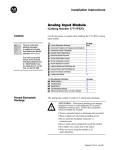
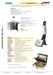
Universal I/O Chassis
(Cat. No. 1771-A1B, -A2B, -A3B, -A3B1,
-A4B Series B)
Installation Data
To the Installer
To install an I/O chassis you
Prepare for Installation
I/Ogrouplabel set (cat. no. 1771XB)
See page
prepare for installation . . . . . . . . . . . . . . . . . . . . . . . . . . . . .
1
allow sufficient mounting space . . . . . . . . . . . . . . . . . . . . . .
2
mount the I/O chassis and ground bus . . . . . . . . . . . . . . . . .
5
ground the chassis . . . . . . . . . . . . . . . . . . . . . . . . . . . . . . .
6
set the power supply configuration jumper . . . . . . . . . . . . . . .
10
set the switches on the backplane assembly . . . . . . . . . . . . .
10
provide power to the I/O chassis . . . . . . . . . . . . . . . . . . . . .
11
install I/O modules . . . . . . . . . . . . . . . . . . . . . . . . . . . . . . . .
12
Make sure you have these items:
Hardware kit (cat. no. 1771RK)
Documentation
(if you are installing I/O modules or power supplies)
plastic keying bands
(number depends on size of chassis)
•
•
•
•
9 →
18→
27→
36→
I/O Module
Cat. No. 1771xxx
User Manual
1771A1B
1771A2B
1771A3B, 1771A3B1
1771A4B
1 star washer
1 cup washer
Power Supply Chassis
Cat. No. 1771xxx
Installation Data
Power Supply
Cat. No. 1771Px
Installation Data
Power Supply Modules
Cat. No. 1771xx
Installation Data
Output Module
Cat. No. 1771xx
Installation Data
for your:
• programmable controller or I/O adapter module
• external power supply and/or power supply chassis
(if you are using external power supplies)
4 flat washers
2 #10-32 nuts
with captive lock washers
• communication modules and/or I/O modules
• powersupply modules
Installation Data
Universal I/O Chassis
1771A1B, A2B, A3B, A3B1, A4B Series B
Allow Sufficient
Mounting Space
For these mounting dimensions
See page
I/O chassis
3
I/O chassis with external power supply
4
Important: Make sure you meet these minimum spacing requirements.
C
102mm
(4")
B
D
51mm (2")
E
153mm
(6")
51mm (2")
A
E
wiring duct
102mm
(4")
102mm
(4")
C
DD
2
153mm
(6")
153mm (6")
wiring duct
A
Minimum distance between a major component and the sides of an enclosure
is 102mm (4 inches).
B
Minimum vertical separation between major components is 153mm (6 inches).
C
Minimum horizontal separation between major components is 102mm
(4 inches).
D
Minimum vertical distance between a major component and the top or
bottom of an enclosure is 153mm (6 inches).
E
Minimum distance between major components and wiring ducts or terminal
strips is 51mm (2 inches).
13082
Installation Data
Universal I/O Chassis
1771A1B, A2B, A3B, A3B1, A4B Series B
I/O Chassis Mounting Dimensions
1771A1B
1771A2B
1771A3B1
1771A4B
591mm
(23.25")
use 1/420 (M6 x 10)
mounting bolts (four places)
337mm
(13.25")
193mm1
(7.60")
16-slot
12-slot
8-slot
464mm
(18.25")
210mm
(8.25")
4-slot
315mm
(12.41")
254mm
(10")
grounding stud
power connector
171mm
(6.75")
483mm
(19.01")
229mm
(9.01")
1771A3B
610mm
(24.01")
16-slot 1771-A4B
12-slot 1771-A3B1
8-slot 1771-A2B
356mm
(14.01")
4-slot 1771-A1B
grounding studs
217mm1
(8.54")
18mm
(0.71")
465mm
(18.31")
483mm
(19.01")
9mm
(0.34")
26mm
(1.02")
178mm
(7")
339mm
(13.35")
use 1/420 (M6 x 10)
mounting bolts (four places)
130mm
(5.10")
1Total maximum depth dimension per installation depends on module wiring and connectors.
12450I
3
Installation Data
Universal I/O Chassis
1771A1B, A2B, A3B, A3B1, A4B Series B
I/O Chassis with External Power Supply Mounting Dimensions
1771A1B
1771A2B
1771A3B1
1771A4B
591mm
(23.25")
use 1/420 (M6 x 10)
mounting bolts (four places)
315mm
(12.41")
You can mount 1771P1, P2, P7 and PS7
power supplies on the left side plate of the
I/O chassis, or up to 5 cablefeet from the I/O chassis.
337mm
(13.25")
16-slot
464mm
(18.25")
210mm
(8.25")
1771P1
1771P2
1771P7
1771PS7
Power Supply
12-slot
8-slot
4-slot
254mm
(10")
grounding stud
91mm
(3.6")
483mm
(19.01")
229mm
(9.01")
610mm
(24.01")
356mm
(14.01")
16-slot 1771-A4B
12-slot 1771-A3B1
8-slot 1771-A2B
4-slot 1771-A1B
12451I
1771A3B
46mm
(1.8")
115mm
(4.53")
A 1771PS7 power supply cannot be mounted on the side
of the 1771A3B I/O chassis. See the installation data for
the 1771PS7 power supply for more information on
mounting the supply to the I/O chassis.
293mm
(11.53")
315mm
(12.41")
1 cable-foot
grounding studs
465mm
(18.31")
483mm
(19.01")
9mm
(0.34")
Depth is 183mm (7.2")
26mm
(1.02")
178mm
(7.01")
339mm
(13.35")
use 1/420 (M6 x 10)
mounting bolts (four places)
130mm
(5.10")
Clearance depth is 221mm (8.7")
4
12452I
Installation Data
Universal I/O Chassis
1771A1B, A2B, A3B, A3B1, A4B Series B
Mount the I/O Chassis
and Ground Bus
If you have this I/O chassis
Type of mount
1771A1B, A2B, A3B1, A4B
panel mount (rear mount)
1771A3B
19" rack mount (front mount) or panel mount (rear mount)
Each enclosure must contain a central ground bus. The ground bus is the
common connection for each chassis within the enclosure and the
enclosure itself. Use either bolts or welded studs to mount the I/O chassis
and central ground bus. If you are mounting a chassis to the back panel of
an enclosure, use 1/4-20 (M6 x 10) mounting bolts.
Stud Mounting of the Backpanel to the Back Wall of the Enclousure
Bolt Mounting of a Ground Bus or Chassis to the Backpanel
back wall of enclosure
backpanel
backpanel
ground bus or
mounting bracket
welded stud
scrape paint on panel
tapped hole
bolt
scrape paint on panel
nut
ground lug
star washer
Use a wire brush to remove
paint from threads to
provide a ground connection.
star washer
nut
flat washer
flat washer
star washer
17664
17665
Stud Mounting of a Ground Bus or Chassis to the Backpanel
back wall of enclosure
mounting bracket
or ground bus
ground lug
welded stud
scrape paint from threads
flat washer
nut
star washer
flat
washer
scrape paint from mounting
bracket or ground bus
17666
ATTENTION: If the mounting brackets of a chassis do not lay
flat before the nuts are tightened, use additional washers as
shims so that the chassis will not be warped by tightening
the nuts. Warping a chassis could damage the backplane and
cause poor connections.
5
Installation Data
Universal I/O Chassis
1771A1B, A2B, A3B, A3B1, A4B Series B
Ground Your I/O Chassis
To properly ground your I/O chassis
See page
verify that your systemdesign plans are using the correct
system grounding configuration . . . . . . . . . . . . . . . . . . . . . .
6
ground the chassis . . . . . . . . . . . . . . . . . . . . . . . . . . . . . . .
7
connect equipment grounding conductors . . . . . . . . . . . . . . .
8
connect a ground bus to the grounding electrode system . . . .
9
ground shielded cables . . . . . . . . . . . . . . . . . . . . . . . . . . . .
9
Verify Grounding Configuration
Remote I/O Systems
enclosure
grounding electrode conductor
ground bus
To grounding
electrode
system
I/O chassis
grounding stud
ExtendedLocal I/O Systems
enclosure
enclosure
ground bus
ground bus
To
grounding
electrode
system
(single
point only)
I/O chassis
grounding stud
extended local I/O cables
19938
6
Installation Data
Universal I/O Chassis
1771A1B, A2B, A3B, A3B1, A4B Series B
Ground the Chassis
This I/O chassis
Has grounding stud(s) located
1771A1B
1771A2B
1771A3B1
1771A4B
ATTENTION: To prevent ground loops from
occurring, use only one grounding stud when
grounding your equipment.
1771A3B1
Important: Use the following information, along with the installation
manual for your programmable controller to ground the I/O chassis and
your I/O modules.
Chassis Ground
Singlepoint Grounding
When you connect grounding conductors to the I/O chassis
grounding stud, place a star washer under the first lug, then
place a nut with captive lock washer on top of each ground lug.
ATTENTION: Use singlepoint grounding for
extendedlocal I/O systems. The systems must be
grounded properly for proper performance.
grounding stud
ground lug
nut with captive washer
star washer
ground lug1
I/O chassis side plate
nut with captive washer
1Use the cup washer if crimpon lugs are not used.
externaltooth washers
#10 threadforming screw
19923
7
Installation Data
Universal I/O Chassis
1771A1B, A2B, A3B, A3B1, A4B Series B
Connect Equipment Grounding Conductor
Connecting Equipment Ground Conductor to a Ground Bus
Connecting Equipment Ground Connector to an Enclosure Wall
ground bus
mounting
enclosure wall
ground bus
equipment
grounding
conductors
bolt
ground lug
nut
ground lug
star washer
tapped hole
star washer
scrape paint from panel
star washer
Grounding electrode conductor
to grounding electrode system
equipment
grounding
conductor
bolt
1 00 20
13271
■
■
■
■
use 2.54cm (1in.) copper braid or 8 AWG copper wire to connect each chassis,
the enclosure and a central ground bus mounted on the backpanel
use a steel enclosure to guard against electromagnetic interference (EMI)
make sure the enclosure door viewing window is a laminated screen or
a conductive optical substrate (to block EMI)
install a bonding wire for electrical contact between the door and the
enclosure; do not rely on the hinge
Important: Do not lay one ground lug directly on top of the other; this type of
connection can become loose due to compression of the metal lugs.
Place the first lug between a star washer and a nut with a captive star washer.
After tightening the nut, place the second lug between the first nut and a second
nut with a captive star washer.
Connect an equipment grounding conductor directly from each chassis to
an individual bolt on the ground bus.
For chassis with
Connect the equipment
grounding conductor using
a ground stud
the grounding stud
no ground stud
a mounting bolt
If the power supply has its own groundable chassis, do not connect the
GND terminal of the power supply. However, when you connect power to
a power supply without a groundable chassis (such as an ac input
power-supply module), you must also use 14 AWG copper wire to connect
its GND terminal to the ground stud or mounting bolt connected to the
ground bus.
8
Installation Data
Universal I/O Chassis
1771A1B, A2B, A3B, A3B1, A4B Series B
Connect Ground Bus to GroundingElectrode System
The grounding-electrode system is at earth-ground potential and is the
central ground for all electrical equipment and ac power within any facility.
Use a grounding-electrode conductor to connect the ground bus to the
grounding-electrode system. Use at minimum 8 AWG copper wire for the
grounding-electrode conductor to guard against EMI. The National
Electrical Code specifies safety requirements for the grounding-electrode
conductor.
Ground Shielded Cables
Certain connections require shielded cables to help reduce the effects of
electrical noise coupling. Ground each shield at one end only. A shield
grounded at both ends forms a ground loop which could cause faulty
PLC-5 processor operation.
Ground each shield at the end specified in the appropriate publication for
the product.
Avoid breaking shields at junction boxes. Many types of connectors for
shielded conductors are available from various manufacturers. If you do
break a shield at a junction box:
connect only category-2 conductors in the junction box
do not strip the shield back any further than necessary to make a
connection
connect the shields of the two cable segments to ensure continuity along
the entire length of the cable
For more information about grounding the chassis, see Programmable
Controller Wiring and Grounding Guidelines (publication 1770-4.1).
9
Installation Data
Universal I/O Chassis
1771A1B, A2B, A3B, A3B1, A4B Series B
Set the Power Supply
Configuration Jumper
Set the power supply configuration jumper according to the power supply
you are using.
ATTENTION: If you do not properly configure the
power supply configuration jumper, the processor will fail.
Y
If you are using
a powersupply module or
a processor with an integral power supply
(1772LSP, LWP, LXP or LZP)
N
Set jumper to
Y N
Using
Power Supply
Module in
the Chassis?
Y" position
Y N
a power supply external to the I/O chassis
N" position
12620I
Important: You cannot power a single I/O chassis with both a
power-supply module and an external power supply.
Set the Switches on the
Backplane Assembly
Use the installation manual for your programmable controller or
adapter module to set the switches.
ATTENTION: If you do not properly configure the backplane
switch assembly, various system failures may occur.
I/O chassis
backplane switch assembly
1
2
3
4
5
6
7 8
OFF
ON
10807-I
10
Installation Data
Universal I/O Chassis
1771A1B, A2B, A3B, A3B1, A4B Series B
Provide Power
to the I/O Chassis
Your I/O chassis can receive power through:
processors with integral power supplies that provide 2-4A
power-supply modules that provide 3-8A
external power supplies that provide 6.5-16A
(external power supplies are not designed for parallel operation)
Power-supply modules are designed for parallel operation. See your power
supply installation documentation for possible configurations.
Important: The 1772-LSP, -LWP, -LXP, and -LZP processor modules
already contain a power supply so you can only parallel one additional
power-supply module with these processor modules.
ATTENTION: Do not connect an external power supply
and a power-supply module to the same I/O chassis;
they are incompatible.
If your I/O chassis is receiving power through
Then
an external power supply or a power supply chassis
continue with this section
powersupply modules
go to page 12
Attaching a Power Supply to an I/O Chassis
The I/O chassis has two power connectors. You connect the external
power supply or power supply chassis (1771-PSC) to the I/O chassis using
these connectors and the appropriate power supply cables.
Important: Use the installation data for your power supply or power
supply chassis to properly mount it to your I/O chassis.
Important: If you mount a power supply to any I/O chassis,
place the flat washers provided between each mounting screw
and the power supply mounting bracket. If you do not use the
flat washers, the mounting screw intrudes into the I/O chassis
and interferes with module insertion.
power supply mounting bracket
flat washer
mounting screw
Ó
ÔÔ
ÑÓÔÔ
ÑÓÔÔ
ÔÔ
ÑÓÔÔ
ÔÔ
This I/O chassis
Has power connectors located
1771A1B
1771A2B
1771A3B1
1771A4B
1771A3B
I/O Chassis
12447I
11
Installation Data
Universal I/O Chassis
1771A1B, A2B, A3B, A3B1, A4B Series B
Install Your I/O Modules
The left-most slot of each chassis accepts either a processor module or an
I/O adapter module. The other slots in the chassis accept communication
modules, I/0 modules and power-supply modules.
1771A2B I/O chassis
I/O adapter module
1771A4B I/O chassis
PLC5 processor
communication cable
I/O modules
lockingbar pins
11865
To insert a module:
front of chassis
12453I
1.
Pull the locking-bar pins to release the locking bar and swing it up.
2.
Use the installation data/user manual for your module to:
a.
position the keying bands in the backplane connectors to
correspond to the key slots on the module. This prevents you
from inserting the wrong module in this slot.
ATTENTION: Observe the following precautions when
inserting or removing keys:
insert or remove keys with your fingers
make sure that key placement is correct
Incorrect keying or the use of a tool can result in damage to
the backplane connector and possible system faults.
I/O chassis
keying bands
backplane
connector
Each I/O module is slotted in two places
at the rear edge of the circuit board.
These slots are intended to mate with the
plastic keys supplied with each chassis.
I/O module
I/O chassis
backplane connector
b.
install the module.
Important: Firmly press the module into the chassis backplane
connector. The chassis locking bar will not close if any
modules are not seated properly.
Repeat for each module you install.
12
19808
Installation Data
Universal I/O Chassis
1771A1B, A2B, A3B, A3B1, A4B Series B
3.
Swing the chassis locking bar down into place to secure the modules.
Make sure the locking pins engage.
4.
Apply the I/O group labels over the scored lines on the I/O chassis
locking bar as shown below. On each label, record the I/O rack
number, I/O group number and terminal numbering for each module.
Examples:
G
I/O Group Label
R
G
G
00
07
10
17
G
00
07
10
17
00
07
10
17
G
00
07
10
17
R
A digital 8point
I/O module has its
terminals numbered:
00-07 (left slot)
or
10-17 (right slot)
A digital 16point
I/O module has its
terminals numbered:
2-slot addressing
(8point I/O modules)
00-07
and
10-17
00
07
10
17
00
07
10
17
G
00
07
10
17
00
07
10
17
R
1-slot addressing
(16point I/O modules)
A digital 32point I/O module
in any slot has its terminals
numbered for two I/O groups.
G
G
G
G
00
07
10
17
00
07
10
17
1st I/O group - 00-07 and 10-17
2nd I/O group - 00-07 and 10-17
G
G
00
07
10
17
00
07
10
17
R
1/2-slot addressing
(32point I/O modules)
placement
locking bar
scored line
G
G
00
07
10
17
G
00
07
10
17
00
07
10
17
G
00
07
10
17
front of chassis
12448I
5.
Use your module’s installation data to make other wiring connections.
6.
Apply power to the system and run tests as required.
13
Installation Data
Universal I/O Chassis
1771A1B, A2B, A3B, A3B1, A4B Series B
Specifications
I/O Chassis
Series B
(C No.)
N )
(Cat.
Type of Mount
General Dimensions
(W x H x D)
Weight
g
(without modules)
I/O Module
Slots
Maximum
Backplane
C
Current
1771A1B
panel
229 x 315 x 193mm
(9.0 x 12.4 x 7.6 inches)
3.6kg (8lbs)
4
1771A2B
panel
356 x 315 x 193mm
(14.0 x 12.4 x 7.6 inches)
4.5kg (10lbs)
1771A3B
panel or
19" rack
483 x 339 x 221mm
(19.0 x 13.35 x 8.7 inches)
1771A3B1
panel
1771A4B
All Chassis
14
Compatible Replacement
for Chassis
Series A
Supersedes
16A
1771A1B
1771A1
8
16A
1771A2B
1771A2
5.9kg (13lbs)
12
24A
1771A3B
none
483 x 315 x 193mm
(19.0 x 12.4 x 7.6 inches)
5.9kg (13lbs)
12
24A
1771A3B1
none
panel
610 x 315 x 193mm
(24.0 x 12.4 x 7.6 inches)
7.3kg (16lbs)
16
24A
1771A4B
1771A4
Operating
Temperature
Storage
Temperature
Relative
Humidity
CSA Certification
(when product is marked)
0o to 60oC
32o to 140oF
-40o to 85oC
(-40o to 185oF)
5 to 95% (without condensation)
Class 1, Division 2, Groups A, B, C and D
Installation Data
Universal I/O Chassis
1771A1B, A2B, A3B, A3B1, A4B Series B
Notes
15
Installation Data
Universal I/O Chassis
1771A1B, A2B, A3B, A3B1, A4B Series B
AllenBradley has been helping its customers improve productivity and quality for 90 years.
AB designs, manufactures and supports a broad range of control and automation products
worldwide. They include logic processors, power and motion control devices, manmachine
interfaces and sensors. AllenBradley is a subsidiary of Rockwell International, one of the
world's leading technology companies.
With major offices worldwide.
Algeria • Argentina • Australia • Austria • Bahrain • Belgium • Brazil • Bulgaria • Canada • Chile • China, PRC • Colombia • Costa Rica • Croatia • Cyprus • Czech
Republic • Denmark • Ecuador • Egypt • El Salvador • Finland • France • Germany • Greece • Guatemala • Honduras • Hong Kong • Hungary • Iceland • India •
Indonesia • Israel • Italy • Jamaica • Japan • Jordan • Korea • Kuwait • Lebanon • Malaysia • Mexico • New Zealand • Norway • Oman • Pakistan • Peru • Philippines
• Poland • Portugal • Puerto Rico • Qatar • Romania • Russia-CIS • Saudi Arabia • Singapore • Slovakia • Slovenia • South Africa, Republic • Spain • Switzerland •
Taiwan • Thailand • The Netherlands • Turkey • United Arab Emirates • United Kingdom • United States • Uruguay • Venezuela • Yugoslavia
World Headquarters, AllenBradley, 1201 South Second Street, Milwaukee, WI 53204 USA, Tel: (1) 414 3822000 Fax: (1) 414 3824444
Publication 17712.210 September 1993
Supersedes 17712.210 September 1992
16
PN 95511561
Copyright 1993 AllenBradley Company, Inc. Printed in USA