1
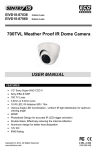
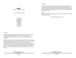
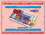
User Manual
Stand-Alone Access Control Slim Type Keypad
with Built-in EM Reader
ACS45K-EM
FEATURES
•
•
•
•
•
•
•
•
•
•
•
•
Outdoor, water resistant
Built-in EM Reader; Card / Code / Combined access
IP65 Rating
125KHz Frequency
1.97 inch / 5 cm Effective distance
Up to 1000 password & card holders for Zone 1
Digital keypad operation
Built-in pickproof function
Watchdog timer, powerful reboot & self-recovery watchdog
Dual relay outputs, 0~99 sec unlock output delay time
12V~15V DC, 150 mA
1.75” x 5.9” x 0.87”
Please read the Manual before attempting to use this product.
Copyright © 2010-2014. All Rights Reserved.
www.sentryus.com
R201408-V25
Disposal of Old Electrical & Electronic Equipment (Applicable in the European Union and
other European countries with separate collection systems).
This symbol on the product or on its packaging indicates that this product shall not be treated as household
waste. Instead it shall be handed over to the applicable collection point for the recycling of electrical and
electronic equipment. By ensuring this product is disposed of correctly, you will help prevent potential
negative consequences for the environment and human health, which could otherwise be caused by
inappropriate waste handling of this product. The recycling of materials will help to conserve natural resources.
For more detailed information about recycling of this product, please contact your local city office, your
household waste disposal service or the shop where you purchased the product.
CAUTION
1. Handle this product with care
Avoid any shock or bumping of the product. Improper handling could damage the product.
2. Requires a proper operating environment
This product should be mounted within an enclosure.
3. Check the power source voltage
The power source voltage should be within the specified range. (Product must meet the specifications).
4. Objects and liquid entry
Never push objects of any kind into this product as this may touch dangerous voltage points of short out
parts that could result in a fire or electric shock. Never spill any kind of liquid on the product.
5. Servicing
Do not attempt to service this product by yourself as opening or removing covers may expose you to
dangerous voltage or other hazards. Refer all service to qualified servicing personnel.
6. Damage requiring service
Unplug this product from the power source and refer service to qualified servicing personnel under the
following conditions:
a. When the power supply cord or plug is damaged.
b. If liquid has been spilled, or objects have fallen into the product.
c. If the product has been exposed to rain or water.
d. If the product has been dropped or the cabinet has been damaged.
2
INDEX
FEATURES ..................................................................................................................................... 1
SAFETY WARNINGS ...................................................................................................................... 2
PACKAGE CONTENTS .................................................................................................................... 4
KEYPAD DESCRIPTION .................................................................................................................. 4
MOUNTING INSTALLATION ........................................................................................................... 5
SYSTEM WIRING DIAGRAM .......................................................................................................... 6
SYSTEM WIRING CONNECTION .................................................................................................... 7
PROGRAMMING & OPERATION ................................................................................................. 7-8
CHANGING PROGRAMMING/ADMIN CODE ........................................................................ 8
RESTORING PROGRAMMING/ADMIN CODE TO FACTORY DEFAULT .................................... 8
ACCESS MODE SETTING ...................................................................................................... 8
LENGTH OF PASSWORD SETTING ........................................................................................ 8
ADDING A MASTER CARD (ZONE 1) .................................................................................... 9
ADDING A USER CARD & CODE ....................................................................................... 9-10
MODIFYING THE USER CODE (ZONE 1) ............................................................................... 10
GROUP CARDS ADDED IN ZONE 1 ...................................................................................... 10
REMOVING ALL USER & CODES .......................................................................................... 11
CHANGING THE UNLOCK DELAY TIME ................................................................................ 11
PICKPROOF ALARM ............................................................................................................ 11
DOOR BELL ......................................................................................................................... 12
RESTORING FACTORY DEFAULT .......................................................................................... 12
SPECIFICATIONS ......................................................................................................................... 13
LIMITED WARRANTY .................................................................................................................. 13
OTHER RELATED PRODUCTS ...................................................................................................... 14
RECOMMENDED LOCK SYSTEMS ................................................................................................ 14
3
PACKAGE CONTENTS
1.
2.
3.
4.
5.
6.
7.
One (1) Access Control Unit
One (1) Mounting Plate
One (1) Short Screw
Four (4) Long Screws
Four (4) Wall Anchors
One (1) Torque Wrench
One (1) Manual
1.
5.
2.
3.
6.
7.
4.
*For any returns, please include all components listed above with original packaging in
Resalable Condition. Absolutely No Returns will be accepted if any component is
missing/damaged.
KEYPAD DESCRIPTION
No.
Description
Mode LED Indicators
Yellow, Red, Green
Door LED Indicators
Antenna
Matrix Keypad
Vandal Proof Case Screw
4
MOUNTING INSTALLATION
Note: Before mounting, decide first where to mount the keypad.
1. Open the control keypad by removing the screw at the bottom using the provided
torque wrench.
2. Push the front cover up a few millimeters and then lift the lower edge (no more than 20
degrees and remove the front cover gently.
2. Punch the necessary holes at the back template for the screws.
3. Using the back template as a guide, drill the holes for the screws and system wiring
(make a bigger hole for the system wiring).
Note: Level the back template
4. Draw out the system wiring through the center hole of the back template.
5. Mount the back template using the screws provided.
6. Mount the front panel using the torque wrench.
7. Connect system wiring (see System Wiring Diagram and System Wiring Connections).
5
SYSTEM WIRING DIAGRAM
Note: White NO 1: For Electric Strike Lock
Aqua NC 1: For Electric Magnetic Lock
Red
=
DC Input:
Black
=
White
=
Pink
=
Aqua
=
Brown
=
Orange
=
Power Negative (-)
Normally Open: N/O
Electric Door Strike Lock
Common - Relay
Normally Close N/C
Magnetic Lock
Door Status Detection
(See * on page 7 for DSD)
Unlocking Button 1
+12V ~ +24V
Yellow
=
Unlocking Button 2
Note: The first 5 wires (bolded) are most important.
6
SYSTEM WIRING CONNECTIONS
Connecting to Power:
Connect the Red to power positive (+).
Connect the Black to power negative (-).
Connecting to Locks (two options):
Option1: Using a Strike Lock
Connect the White to power positive (+).
Connect the Pink to the Strike lock power positive (+) or the normally open (NO).
Connect the Strike lock power negative (-) to the power negative (-).
Option 2:Using a Magnetic Lock
Connect the Aqua to power positive (+).
Connect the Pink to the Magnetic lock power positive (+) or the normally close (NC).
Connect the Magnetic lock power negative (-) to the power negative (-).
Connecting an Unlocking Button to Open the Door from the Inside:
Connect the Orange to the button NO for Strike lock or NC for Magnetic lock.
Connect the button negative (-) or common to power negative (-).
Connecting to Button 2:
Connect the Yellow to the button NO for Strike lock or NC for Magnetic lock.
Connect the button negative (-) to power (-).
Connecting the Door Status Detection:
Connect the Brown to the sensor positive (+).
Connect the sensor negative (-) to power negative (-).
*The Door Status Detection (DSD) will automatically lock the door once a connection is
detected. When a person comes in, it will not wait for the delay time to lock the door but
locks it automatically when connection is detected. This is a good way to prevent someone
coming in from behind a person who has access.
PROGRAMMING & OPERATION
*All programming need to go to Setup Mode first.
Two-zone relays can be programmed for opening the lock. Up to 1000 user cards and
correlative codes can be stored into ZONE 1 and up to 10 user cards or codes can be stored
into ZONE 2. In addition the ZONE 1 can be programmed for 3 modes to open the lock: only
the card access, both the code and card access, or combined access. The ZONE 2 could be
programmed for door bell.
7
The Factory Default Programming/Admin Code is 1 2 3 4.
To enter Setup Mode press Programming Code twice.
(ex: 1 2 3 4 1 2 3 4) The mode LED indicator will turn yellow.
To exit or quit from the Setup Mode, press # key.
CHANGING PROGRAMMING/ADMIN CODE
1.
2.
3.
In Setup Mode, press * key and 3. The mode indictor will flash yellow.
Enter new Programming Code twice (ex: 5 6 7 8 5 6 7 8). A long beep means
Programming Code was changed. The length of the Programming/Admin Code must
be the same as the old one.
Exit Setup Mode.
RESTORING THE PROGRAMMING/ADMIN CODE TO FACTORY DEFAULT
*Only if you cannot remember your new Programming Code.
1. Turn off control keypad power.
2. While pressing # key, turn on the power of the control keypad. A long beeps means
the default Programming Code was restored. (Programming/Admin Code is 1 2 3 4)
3. Exit Setup Mode.
ACCESS MODE SETTING
Card Access Only:
1. In Setup Mode, press * key and 0. The mode LED indicator will flash yellow.
2. Press 0 twice. The mode LED indicator will turn yellow and a long beep will sound.
Card & Code Access:
1. In Setup Mode, press * key and 0. The mode LED indicator will flash yellow.
2. Press 0 and 1. The mode LED indicator will turn yellow and a long beep will sound.
Combined Access:
1. In Setup Mode, press * key and 0. The mode LED indicator will flash yellow.
2. Press 0 and 2. The mode LED indicator will turn yellow and a long beep will sound.
To exit or quit from Setup Mode, press # key.
LENGTH OF PASSWORD SETTING
1.
2.
In Setup Mode, press * key and 9. The mode LED indicator will flash yellow.
Press 0 and 4. When a “BI” sound beeps, enter X (X = 2 / 3 / 4 / 5 / 6).
Note: 2 = length of 2 digits (00-99)
3 = length of 3 digits (000-999)
4 = length of 4 digits (0000-9999)
5 = length of 5 digits (00000-99999)
6 = length of 6 digits (000000-999999)
A “BI” sound means digit length setting is successful. A “BI BI BI” sounds means digit length is
the same as the existing, so setting is not permitted.
To exit or quit from Setup Mode, press # key.
IMPORTANT NOTE: In case the digit length changed, all added cards and passwords will be
8
cleared.
ADDING A MASTER CARD (ONLY FOR ZONE 1)
Note: It is advisable to install the Master Card first before installing any User Cards
To Add a Master Card:
1. In Setup Mode, press * key and 7. The mode LED indicator will flash green
indicating there is no master card. If the mode LED indicator turns red, a Master
Card is already stored. To clean up and remove, press * key twice.
2. Swipe Master Card. A long beep means master card was stored.
3. Press # key to exit Setup Mode.
Using Master Card to Enter and Exit Setup Mode:
1. Swipe Master Card. A long beep will sound and the mode LED indicator will flash
yellow. This means that you are in Setup Mode.
2. Exit Setup Mode by swiping Master Card again. Three rapid beeps and the mode
LED indicator will turn green means that you have exited the Setup Mode.
The access control will be locked for 60 seconds if one of the following occurs:
•
A wrong code is entered continuously
•
An invalid card is swiped 5 times
When a door is opened and then closed, the system will automatically detect the door status
and lock the door even though it is still in delay period (for ZONE 1 only).
IMPORTANT NOTE: The user code must be different from the Programming/Admin Code. The
code of ZONE 1 must be different from that of ZONE 2.
ADDING A USER CARD & CODE
ZONE 1:
1. In Setup Mode, press one number from 000-999 data storage units. Yellow LED
indicator will flash.
2. At the same time, if red LED indicator is flashing, this means the number data
storage unit existed. Press * key twice to clean up. If green LED indicator is flashing,
this means the number data storage unit can add card(s) and password(s).
To add cards and passwords:
1. Enter Setup Mode. The yellow LED indicator will flash.
2. Input a 3-digit number from 000-999 data storage units and the green LED indicator
will also flash.
3. Swipe card and a sound “BI” means the card was successfully added. Then input the
correlative passwords. The length of the password should be the same as the
Programming/Admin Code. After the “BI” sound, this means the card is added and
the passwords are set successfully.
4. Press # key to exit Setup Mode and standby.
To delete cards and passwords:
1. Enter Setup Mode.
2. Input a 3-digit number form 000-999 data storage units. If red LED indicator is on, it
means there is data stored in this set of unit.
3. Press * key twice to delete the card and password/code.
4. Press # key to exit Setup Mode and standby.
9
ZONE 2:
1. In Setup Mode, press * key and 4.
2. Input a 2-digit number from 00-99 data storage unit. Yellow LED indicator will flash.
3. At the same time, if red LED indicator is flashing, this means the number data
storage unit existed. Press * key twice to clean up. If green LED indicator is flashing,
this means the number data storage unit can add card(s) and password(s).
To add cards and passwords:
1. Enter Setup Mode. The yellow LED indicator will flash.
2. Input a 3-digit number from 000-999 data storage units and the greeen LED
indicator will also flash.
3. Swipe card and a sound “BI” means the card has successfully been added. Then
input the correlative passwords. The length of passwords should be the same as the
Programming/Admin Code. After the “BI” sound, this means the card is added and
the passwords are set successfully.
4. Press # key to exit Setup Mode and standby.
To delete cards and passwords:
1. Enter Setup Mode. Press * key and 4.
2. Input a 2-digit number form 00-99 data storage units. If red LED indicator is on, it
means there is data stored in this set of unit.
3. Press * key twice to delete the card and password/code.
4. Press # key to exit Setup Mode and standby.
MODIFYING THE USER CODE (ZONE 1)
1.
2.
3.
4.
In Setup Mode, press * key and 9. The mode LED indicator will flash yellow.
Press 0 and 2. A beep will sound.
Input 3-digit number form 000-999 data storage units and input the correlative
passwords. (The length of relative passwords should be the same as the
Programming/Admin Code).
Press # key to exit Setup Mode.
GROUP CARDS ADDED IN ZONE 1
1.
2.
3.
4.
In Setup Mode, press * key and 9. The mode LED indicator will flash yellow.
Press 0 and 1.
Input the 3-digit numbers from 000-999 for data storage unit starting number and
then another 3-digit number for the whole cards account you want to add.
(ex: Input “005 060” – means the cards added in storage units start at 005 and the
number of cards added are 60 cards).
Press # key to exit Setup Mode.
Swipe the first added card or input the first added card serial number (8 digits). A beep will
sound indicating the addition is successful.
10
REMOVING ALL USER & CODES
1.
2.
3.
In Setup Mode, press * key and 8. The mode LED indicator will flash yellow.
Press 8 twice. A long beep means all users and their codes were removed (except
for Programming/Admin Code).
Press # key to exit Setup Mode.
CHANGING THE UNLOCK DELAY TIME
ZONE 1:
1. In Setup Mode, press * key and 1. The mode LED indicator will flash yellow.
2. Enter unlocking delay time from 00-99 (ex: 10 means ten seconds delay time before
it locks). A long beep means unlock delay time was adjusted. If setting lock-time is
00: swipe card or input password once and open the door, then swipe card for input
password again and close the door.
3. Press # key to exit Setup Mode.
ZONE 2:
1. In Setup Mode, press * key and 5. The mode LED indicator will flash yellow.
2. Enter unlocking delay time from 00-99 (ex: 10 means ten seconds delay time before
it locks). A long beep means unlock delay time was adjusted. If setting lock-time is
00: swipe card or input password once and open the door, then swipe card for input
password again and close the door.
3. Press # key to exit Setup Mode.
PICKPROOF ALARM
The built-in buzzer will send a continuous beeping if the photoresistor sensor is directly
exposed into the light. The buzzer will turn off automatically in 60 seconds. The light is no
longer detected by entering the programming/admin code.
To turn on:
1. In Setup Mode, press * key and 6. The mode LED indicator will flash yellow.
2. Press 0 and 2. A long beep will sound and the mode LED indicator will turn yellow
to indicate that pickproof alarm was turned on.
3. Press # key to exit Setup Mode.
To turn off:
1. In Setup Mode, press * key and 6. The mode LED indicator will flash yellow.
2. Press 0 and 1. A long beep will sound and the mode LED indicator will turn yellow
to indicate that pickproof alarm was turned off.
3. Press # key to exit Setup Mode.
Note: If the photoresistor is directly exposed into the light, a
buzzing sound will be heard. It will only stop upon removing
the light exposed directly to the photoresistor, the
Programming/Admin Code was pressed or after 60 seconds.
11
DOOR BELL
To turn on:
1. In Setup Mode, press * key and 2. The mode LED indicator will flash yellow.
2. Press 0 and 2. A long beep will sound and the mode LED indicator will turn yellow
to indicate that door bell was turned on.
3. Press # key to exit Setup Mode.
To turn off:
1. In Setup Mode, press * key and 2. The mode LED indicator will flash yellow.
2. Press 0 and 1. A long beep will sound and the mode LED indicator will turn yellow
to indicate that door bell was turned off.
3. Press # key to exit Setup Mode.
Note: The relay in ZONE 2 for door bell is unavailable if the function of door bell is turned on
but the function or door lock is inactive. Press the * key in standby mode, the relay contacts
one time, the door bell ringing is triggered.
RESTORING FACTORY DEFAULT
1.
2.
3.
4.
5.
In Setup Mode, press * key and 8. The mode LED indicator will flash yellow.
Press 8 twice. A continuous long beep means all user cards and codes have been
cleared out.
Press * key and 8. The mode LED indicator will flash yellow.
Press 9 twice. A continuous long beep means factory default is restored.
Press # key to exit Setup Mode and standby.
If done improperly, the device will beep and revert back without any actions in 30 seconds.
During the access mode setting, there is a 5-second window to either input password or
swipe card. If no action is taken within 5 seconds, it will revert back.
When ZONE 1 relay is activated, the door LED indicator light will turn green. When ZONE 2
relay is activated, the door LED indicator light will turn red.
If you forget the Programming/Admin Code, press and hold # key, then power on the device.
A beep will sound indicating the default Programming/Admin Code setting is successful.
2-digit Length – default code is 12
3-digit Length – default code is 123
4-digit Length – default code is 1234
5-digit Length – default code is 12345
6-digit Length – default code is 123456 (max.)
12
SPECIFICATIONS
Model
Capacity
EM Reader Frequency
Card Effective Distance
Power Consumption
DC Input
AC input
Current
Unlock Delay Time
IP Rating
Operating Temperature
Humidity
Dimension
ACS45K-EM
1000 passwords & card holders (Zone 1)
10 passwords or card holders (Zone 2)
125 KHz
1.97 inch / 5 cm
12V~15V DC, 150mA
+12V ~ +24V
~9V ~ 18V
< 80 mA Standby / < 110 mA Working
0~99 sec
IP65
-20°C ~ 50°C
RH < 95%
1.75”(W) x 5.9”(H) x 0.87”(D)
150mm(W) x 45mm(H) x 20mm(D)
*Specifications are subject to change without notice
LIMITED WARRANTY
LIMITED ONE (1) YEAR WARRANTY AND EXCLUSIONS
Manufacturer warrants to the original consumer purchaser and not for the benefit of anyone else that
this product at the time of its sale by Manufacturer is free of defects in materials and workmanship
under normal and proper use for one (1) year from the purchase date. Manufacturer's only obligation is
to correct such defects by repair or replacement, at its option, if within such one (1) year period the
product is returned prepaid, with proof of purchase date, and a description of the problem. This warrant
excludes and there is disclaimed liability for labor for removal of this product or reinstallation. This
warranty is void if this product is installed improperly or in an improper environment, overloaded,
misused, opened, abused, or altered in any manner, or is not used under normal operating conditions
or not in accordance with any labels or instructions. There are no other implied warranties of any
kind, including merchantability and fitness or a particular purpose, but if any implied warranty is
required by the applicable jurisdiction, the duration of any such implied warrant, including
merchantability and fitness of or a particular purpose, is limited to one (1) year. Manufacturer is not
liable for incidental, indirect, special, or consequential damages, including without limitation, damage
to, or loss of use of, any equipment, loss sales or profits or delay or failure to perform this warranty
obligation. The remedies, provided therein are the exclusive remedies under this warranty, whether
based on contract, tort or otherwise.
13
OTHER RELATED PRODUCT OPTIONS
A.
Buzzer
• Can be programmed 1~10 sec, recommend 5 sec.
• 5V~14V DC
Buzzer Connection:
1. Connect the buzzer positive (+) to lock (magnetic or strike) positive (+)
2. Connect the buzzer negative (-) to power negative (-)
B-1.
2-CH Wireless RF Receiver & Remote
+
RF Receiver
B-2.
OR
Single Button Remote
2-button Remote
2-CH Wireless RF Receiver & Desktop RF Transmitter
+
RF Receiver
C.
RF Transmitter
Hands-free Video Intercom System
+
Outdoor Station w/ Camera
NC-CS2
+
Monitor Inside Station
NC-MON4
Power Supply
AC-POWERDC
RECOMMENDED LOCK SYSTEMS
A.
Magnetic Lock with LED
- Available in 600 lbs and 1200 lbs
B.
Electric Door Strikes for Metal Doors
- Jaw strength: 2000 lbs
- 12V DC
C.
Electric Door Strikes for Wood Doors
- Jaw strength: 2000 lbs
- 12V DC
Copyright © 2010-2014. All Rights Reserved.
www.sentryus.com
14
R201408-V25