1
1.
USER MANUAL
PROJECT FIFTY
TUNER
SPHINX
Project Fifty
1. UNPACKING .......................................................................................................................................3
2. SPHINX WARRANTY CARD ..............................................................................................................3
3. THE TUNER AT A GLANCE...............................................................................................................4
Front panel................................................................................................................................................... 4
Rear panel ................................................................................................................................................... 5
4. DISPLAY .............................................................................................................................................6
5. INSTALLATION AND CONNECTIONS ..............................................................................................7
Installation.................................................................................................................................................... 7
Connecting the mains cable ........................................................................................................................ 7
Connecting the amplifier .............................................................................................................................. 7
Connecting the optical cables...................................................................................................................... 7
Connecting the antenna............................................................................................................................... 7
6. OPERATION........................................................................................................................................8
Power on/off................................................................................................................................................. 8
Antenna input sensitivity .............................................................................................................................. 8
Selecting AM or FM ..................................................................................................................................... 8
Auto Tuning.................................................................................................................................................. 8
Manual Tuning ............................................................................................................................................. 8
Direct Access............................................................................................................................................... 8
Signal strength............................................................................................................................................. 9
Frequency indication.................................................................................................................................... 9
Tuned indication .......................................................................................................................................... 9
Bandwidth selection ..................................................................................................................................... 9
Stereo / Mono .............................................................................................................................................. 9
Station memory............................................................................................................................................ 9
Auto Search / Auto Store ........................................................................................................................... 10
Changing memory data.............................................................................................................................. 10
Move station to other memory ................................................................................................................... 10
Selecting a Preset...................................................................................................................................... 11
Remove station from memory.................................................................................................................... 11
Clear all memories..................................................................................................................................... 11
RDS (RADIO DATA SYSTEM)..............................................................................................................11
Radiotext.................................................................................................................................................... 11
RDS Time .................................................................................................................................................. 11
Station identification................................................................................................................................... 11
Program Type recognition (PTY) ............................................................................................................... 11
RDS Data Out ............................................................................................................................................ 11
7. CHANGING PRESETS......................................................................................................................12
Default settings .......................................................................................................................................... 12
Direct Access settings ............................................................................................................................... 12
SETUP settings.......................................................................................................................................... 13
1. FREQ settings ..................................................................................................................................... 13
2. MEM settings ....................................................................................................................................... 14
3. RDS settings........................................................................................................................................ 14
8. RDS IMPORTANT INFORMATION ..................................................................................................16
RDS Radio Data System ........................................................................................................................... 16
Program Type (PTY) .................................................................................................................................. 16
SPHINX REMOTE CONTROL ..............................................................................................................17
Operation ................................................................................................................................................... 18
Selecting without switching ........................................................................................................................ 18
Batteries..................................................................................................................................................... 18
Encountering problems.............................................................................................................................. 18
CARE AND MAINTENANCE.................................................................................................................19
TECHNICAL SPECIFICATIONS ...........................................................................................................19
2
SPHINX
Congratulations with your purchase of the
Sphinx Project Fifty!
You are now a member of an ever increasing group
of quality conscious audiophiles using Sphinx
products.
We are very proud of the tradition connected to the
SPHINX name especially concerning audio quality
perfection.
This manual will help you to gain a maximum
amount of pleasure and quality from your new
Sphinx Project Fifty Tuner.
The Project Fifty's heart is based upon the tuner
section of the legendary 'Five', the rest is of
completely new design. Much attention has been
paid to the prevention of noise signals from
appearing in order to maximise the 'cleanliness' of
the audio signal.
Features like the full-metal housing of the tuner
section or the four completely separate power
supplies (3 analogue, 1 digital) are only a small
example.
The tuner has 99 memories (FM and AM), a tuning
accuracy of 50 kHz and it is completely
programmable (RDS, display, etc.).
It can be operated with just six buttons and two
large rotary controllers: the latter offering that wellknown analogue 'feel' although the tuner is digital
throughout. A full-function Remote is supplied as
standard.
Project Fifty
1. UNPACKING
Before leaving the factory every Project Fifty is
subjected to stringent and extensive technical and
exterior quality inspections.
This ensures you will enjoy many years of high
quality audio from a perfect looking product.
After unpacking your Project Fifty we therefore
recommend you carefully check it for any transport
damage.
In case of damage: please contact your Sphinx
dealer immediately and retain all packing materials
for possible proof of damage and possible claims.
Even if the component is in perfect condition you
still should keep the packing materials. If you need
to transport your Project Fifty at a later time it will
be best protected by the original packing materials.
2. SPHINX WARRANTY CARD
Please take this opportunity to fill out the enclosed
warranty card now!
Follow the instructions on the card or consult your
dealer.
Please send the card as soon as possible to the
return address (within 14 days after purchase).
To obtain the maximum quality from this tuner it is
necessary to use it with top quality audio
components. So preferably use it with other Sphinx
components.
Please read this manual carefully before you
install or use the Project Fifty.
It is important to familiarise yourself with the
special functions, operation and possibilities
of the Sphinx Project Fifty.
Your local dealer will be able to answer any
questions concerning other Sphinx audio
components.
3
SPHINX
Project Fifty
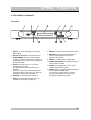
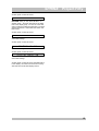
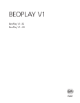
3. THE TUNER AT A GLANCE
Front panel
1. SELECT: To select the display mode: FREQ,
RDS or MEM.
2. Window for IR signals from Remote Control.
3. STEREO/MONO: This button selects MONO
reception (for instance when stereo reception is
degraded by noise). Simultaneously it deselects
the MUTING mode.
4. SETUP: Press this button for 2 seconds to
activate the Setup mode.
The display shows the first parameter to be
adjusted.
Each button press selects the next parameter.
To leave the Setup mode at any time: press the
STANDBY button (5) (see also page 6).
5. STANDBY: To switch the tuner on and off.
7. FM/AM: To select the AM or FM frequency band.
8. MAN/AUTO: This button selects whether the
VALUE controller operates in manual or
automatic tuning mode.
9. ENTER: To activate memory programming.
10. STEREO INDICATION: LED will light red when a
stereo signal is received.
11. TUNED: LED will light green as soon as the
station has been tuned correctly.
12. VALUE: Use this controller to change a setting in
the RDS, MEM or FREQ. display.
For instance to start (automatic or manual)
tuning in FREQ display: turn left for lower
frequencies and right for the higher.
6. Display: Shows all important data (for more
information see Chapter 4. DISPLAY).
4
SPHINX
Project Fifty
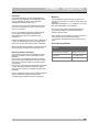
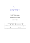
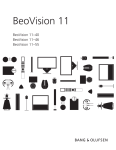
Rear panel
13.
Antenna: 75 Ω antenna input to connect coax
cable from your external antenna (ANTENNA)
(coax DIN 45 325)
14.
Cable: 75 Ω antenna input to connect coax
cable from your cable system (CABLE) (coax
DIN 45 325)
15.
AM/Loop antenna: To connect an external AM
antenna or an AM Loop Antenna.
16.
WARNING!: Here you will find important safety
symbols and instructions regarding the safe
operation of this product.
17.
RDS DATA OUT: To connect a 9-pin sub-D
cable from a PC.
18.
Manufacturer's label: This shows important
data for the component such as serial number
and mains power voltage.
19.
OUT R: Unbalanced output, connect this to the
Right tuner input of the amplifier with a cinch
cable.
OUT L: Unbalanced output, connect this to the
Left tuner input of the amplifier with a cinch
cable.
20.
BALANCED OUT R: To connect the XLR
signal cable from the right (balanced) CD input
of the pre-amp.
BALANCED OUT L: To connect the XLR
signal cable from the left (balanced) CD input
of the pre-amp.
21.
Control In: To connect the optical cable from
the switching source.
Control Out: To connect the optical cable to
the next component.
22.
AC POWER: Connect the mains cable to a
mains power outlet (100 - 240 VAC).
Here you'll also find the Power Switch (O /--)
and the fuse.
5
SPHINX
Project Fifty
4. DISPLAY
The display of the Project Fifty can show several
kinds of information, dependent upon the mode
selected: FREQ, RDS or MEM.
Use the SELECT controller (1) or the RW button
(Remote, 10) to select the mode.
Then use the VALUE controller or the FW button
(Remote, 11) to:
- FREQ change the frequency (tune)
- MEM select a memory
- RDS select information to be displayed
When the display is in RDS mode you might see
(for instance)…:
RDS : POP M
…the type of music or…
RDS : RADIO3FM
…the station identification or…
In standby mode the display will show:
-
RDS : 14:18
…the time or…
After pressing the STANDBY button (5) first you
see…:
DE ZINDERENDE ZATERDAG
SPHINX PROJECT 50
…the RDS 'moving billboard' that shows specific
data from the station.
…and then (for instance):
FREQ: [] FM 87.50MHz
This specific display means there are no stations
selected, the tuner is at the beginning of the
frequency band.
It is also possible that a station has been
programmed and then you will see (for instance):
FREQ: [] FM 96.80MHz
When the tuner is in MEM mode display you might
see (for instance):
MEM : 3 RADIO 3FM
…meaning you have selected Preset 3 and the
station is stored into memory as "Radio 3 FM".
More detailed information about the settings and
changing the parameters via Setup mode can be
found in Chapter 7.
This FM station transmits at 96.80 MHz and the '[ ]'
indicator in front of 'FM' shows that the WIDE
bandwidth is selected.
6
SPHINX
Project Fifty
5. INSTALLATION AND CONNECTIONS
Installation
Connecting the optical cables
The Project Fifty will not become very hot, so
placement is not critical. Although you should not
place it on top of or near other heat-radiating
equipment (such as power amps) or in direct
sunlight.
If you need to use the pre-amp in a closed cabinet
or on a bookshelf you absolutely must provide
unrestricted ventilation around the component.
When the optical output of a Sphinx Project Two or
Eight is connected to the optical input (21) of the
Project Fifty, you do not have to use the STANDBY
switch (5). The tuner will automatically select
Standby mode as soon as the other component is
set to standby.
To prevent any possible interference: keep power
supply cables away from all audio cables.
If all these conditions are met the Project Fifty will
perform to the extremely high standards it is
designed for.
Connecting the mains cable
Before you connect the cable check whether the
mains voltage indicated on the manufacturer's
label (18) on the rear panel is the same as your
local mains voltage.
If not: please contact your dealer and do not connect
the component to the mains.
Connect the tuner to a mains power as indicated on
the Manufacturer's Label (18).
If you would like to switch the component on and off
centrally, you may connect it to a switched AC outlet
of an amplifier.
Connecting the amplifier
Before you start connecting equipment it is always
wise to check whether all mains power cables of all
components are disconnected from the mains
outlets! This will prevent any damage to the
loudspeakers and amplifiers caused by incorrect
wiring or settings.
Ensure proper connection of the optical cables (from
CONTROL OUT to CONTROL IN), otherwise the
display will not show '-- ' although the standby mode
is activated.
If the Project Fifty is placed in strong direct sunlight
the standby mode may self-activate. In that case you
should place the supplied dummy connector in the
Control In (21) input (but only if this is not being
used).
Connecting the antenna
Optimum reception quality - especially for FM stereo
broadcasts - is only guaranteed with a good antenna
system (broadband cable, external antenna or a
central antenna system).
The Project Fifty has two 75 ohm coax-connections:
ANTENNA and CABLE. Connect your (external)
house antenna to ANTENNA (13) and the
broadband cable system to CABLE (14). You may
select the desired antenna input via the FREQ.
Setup menu-item ANTENNA/CABLE.
The supplied stray current protection filter should be
connected between cable and antenna input. This
filter ensures 100% galvanic isolation between
antenna cable and tuner and thus prevents any stray
currents (noise!) on the shield of the cable from
entering the input.
Connect the OUTPUT connectors (19 or 20) to the
TUNER input of the amplifier.
Make sure you connect L and R properly:
L = left channel (white)
R = right channel (red)
Use the AM/LOOP ANTENNA (15) connectors for an
AM Loop Antenna (not supplied). For best results
use a swivel-frame antenna and position the base of
this antenna at the best possible position (e.g. near
a window). If you attach it to or place it close to the
metal rear panel of the housing the reception quality
will decrease.
The XLR connectors are marked RIGHT and LEFT.
When making the connections please refer to the
descriptions for parts 13. up to 22. on page 5.
You may also use an external wire antenna: connect
the antenna wire to the Ψ socket and the earth wire
to the socket.
7
SPHINX
Project Fifty
6. OPERATION
Power on/off
Selecting AM or FM
Connect the power cable of the Project Fifty to a wall
outlet.
Select the desired band (AM or FM) with the FM/AM
button (7).
If you recall a programmed station from memory the
correct band for this station is automatically selected
and displayed.
After you have finished connecting all components,
you can power on the Project Fifty with the power
switch on the rear panel (22.).
The display will show the following:
The Project Fifty is now in standby mode.
After this you only switch the Project Fifty on and off
with the STANDBY button (5.). This way the
electronic circuits will be kept at optimum working
temperature so you can enjoy maximum audio
quality immediately after switching-on. In addition to
that, it significantly increases the life span of the
component.
If you have connected the Project Fifty to an AC
outlet of an amplifier you should leave the ON/OFF
switch to ON. The power switch of the amplifier now
serves as master switch.
It is then always possible to switch the Project Fifty
to standby with the STANDBY button (5).
You switch the Project Fifty on with the STANDBY
button. The display shows:
SPHINX PROJECT 50
after which the station details appear.
Note: The LAST STATION MEMORY function
assures this will be the same station that was
selected before switching off.
After switching on the display is also activated. The
default brightness is 100%, this can be adjusted –
via Setup – to 75, 50 or 25%.
Antenna input sensitivity
The default input is CABLE. To receive broadcasts
via the outside antenna, select the ANTENNA (13)
input. The display will show ANTENNA.
The correct antenna input can be set via the Setup
menu: the display will show the selected input.
A broadband cable network may provide high signal
levels to the input, which may cause reception
disturbances. For this reason, selecting the CABLE
input also activates a -10 dB signal attenuator. This
reduces the sensitivity and decreases reception
distortion. This setting is automatically stored with
the tuned station.
Auto Tuning
You select the AUTO TUNING feature by pressing
the MAN/AUTO button (8) or the button (Remote
8): the display briefly shows "AUTO". If you now
move the VALUE knob (to the left or right) the tuner
will start searching and will stop at the first station
with a strong enough signal.
Another move of the VALUE knob or the button
restarts the search.
Note: Stations with a signal strength below the
adjustable threshold (see Search Level, page 13)
will be skipped. These can be tuned manually.
During auto tuning you can stop the search by
slightly moving the VALUE knob.
Manual Tuning
Om You select the MAN TUNING feature by
pressing the MAN/AUTO button (8) or the button
(Remote 8): the display briefly shows "MAN".
Use the VALUE knob (12) or the TUNING buttons
(Remote 3) to tune to a higher (turn right or press )
or lower frequency (left or ).
Note: The smallest 'step' is 50 kHz (FM) or 9 kHz
(AM).
If you hold the knob or press the button longer, a
'fast search' function is activated in order to
decrease the search time.
Note: During manual tuning the audio output is
muted.
Direct Access
The Direct Access option enables you to directly
enter the station's frequency or memory location via
the Remote numeric keypad.
For memory: First select the MEM display using the
FF- of RW buttons (10 or 11) of the Remote Control.
Then use the numeric keypad to input the location.
The station will be active immediately.
For frequency: First select the FREQ display using
the FF- of RW buttons (10 or 11) of the Remote
Control. Then use the numeric keypad to input the
frequency. After the frequency has been entered
completely, it appears for two seconds in the FREQ
display with "DIRECT" in front of it (for instance):
DIRECT FREQ: 96.80MHz
Note: This function is 'intelligent'. You can only input
valid values between 88 and 108 (for instance 91.10
or 91.25), others (like 91.18) are not accepted.
8
SPHINX
And when you input '1' the '0' is automatically added
while all frequencies starting with '1' also have a '0'.
For AM you may enter any value: the tuner then
selects the closest frequency in the AM spectrum
grid.
Signal strength
The signal level of a station (as received by the
antenna input) is displayed by a vertical bar (max. 7
lines) in the FREQ display. The higher the bar, the
stronger the received signal.
You may select a more detailed indication by
pressing the ; button (Remote 7). The display
switches to a special signal level meter.
SignalLevel: | | | | | |
When the last bar is illuminated the signal strength
is at maximum (100%).
Frequency indication
The frequency of the station is displayed in kHz (AM)
or MHz (FM).
Directly after tuning a new station the FREQ display
shows the RDS station identification which
disappears after 3 sec.
This RDS information – plus all extra data – will be
displayed continuously in the RDS display.
Tuned indication
As soon as a station has been tuned correctly the
TUNED indication (11) will light: this will guarantee
maximum reception quality. After this you may store
the station into memory or you may just listen to it.
Project Fifty
MUTING is active and the signal strength is below
the muting threshold.
Station memory
There are 99 memory locations available. You may
store an AM or FM station by using the following
procedure.
•
First tune (auto or manual) to the station. As
soon as the tuning is correct (for FM the TUNED
indication will light), you may store the station
into memory.
•
Press the ENTER button (9): the first free
lowest-numbered location is shown (blinking).
•
Using the VALUE knob you may select another
location.
•
By pressing the ENTER button again the station
is stored on the location selected.
•
Simultaneously the blinking cursor jumps to the
first character of the station name (max. 8
chars). This can be the RDS Station ID or the
text "NO NAME" for non-RDS stations.
You may change this to your own liking using
the 95 different characters available: dots,
commas, lower case, numbers, etc.
You select the character with the VALUE knob
and the cursor position with the SELECT knob.
•
After everything has been set to your liking,
press ENTER. The display shows
"PROGRAMMED" and the station is stored with
the new name.
Note: The selected MONO or STEREO setting is
stored automatically for each FM station.
Note: When all memory locations are in use, the first
location made available will be MEM 1. Storing the
new settings will overwrite the old ones.
Bandwidth selection
Strong adjacent stations - transmitting on almost the
same frequency as the station listened to - may
degrade reception quality. If that is the case you can
increase the selectivity of the tuner to improve
reception by selecting a narrow bandwidth
(NARROW).
The bandwidth can be selected in the FREQ display
via the Setup menu (see Chapter 7).
A small bandwidth increases the selectivity. The
FREQ display will then change from '[ ]' to ']['.
Stereo / Mono
Normally stereo FM stations are also received in
stereo. As soon as a good quality stereo signal is
received the STEREO indication (10) will light.
If the stereo reception is being disturbed (e.g. due to
a weak signal) this indication will disappear. The
MUTING however remains active so noise, etc. will
be reduced.
In this case you may switch the tuner to MONO by
pressing the STEREO/MONO button (3). The new
setting is displayed for 3 sec.
The MUTING mode is also de-activated so you now
are able to tune to very weak stations. Because in
STEREO mode mono stations may be skipped while
9
SPHINX
1.
Auto Search / Auto Store
The Project Fifty also has an automatic memory
store function: AUTO STORE. After activating this
the tuner will search the frequency band (starting
with the lowest) and automatically store all received
stations into memory, in the order they were found.
Note:
1. This function only works for FM.
2. The first time stations are stored starting at
MEM1.
3. Each successive AUTO SEARCH will store
stations starting at the first available location.
Select the FREQ display and press SETUP until you
see:
2.
3.
AUTO STORE: NO
Change NO into YES with the VALUE knob and
press SETUP again. Now you'll see:
ANT INPUT: CABLE
Cable is the default. if you want to use AutoStore
with your external antenna, select ANTENNA with
the VALUE knob. Press SETUP again. Now you'll
see:
Again change NO into YES with the VALUE knob
and press SETUP. Now you'll see:
AUTO SEARCH / STORE
And after a few seconds:
SEARCH : FM 87.50MHz
The frequency value will continually increase.
As soon as a station is found you'll see:
STORE : FM 87.50MHz
This station will be programmed into the first
memory. This will continue until the end of the
frequency band. Then you'll see:
XX STATIONS FOUND
Note: Each time you activate the AUTO STORE
function, the stations will be stored starting from the
first available location.
After the whole band has been searched, the tuner
deselects SETUP mode and you will see the MEM
display and the content of the first memory.
MEM : 1 Radio3FM
With the VALUE knob you can select every memory,
check the data and (if necessary) change the data.
This function might result in some small problems
which are not caused by the tuner:
4.
Project Fifty
Due to irregularities in the cable signal it is
possible that a station has been stored twice
(with slightly different frequencies). Or a station
has not been stored although it is there.
This is due to the cable signal not conforming to
the standards.
Using the station tables as supplied by the
cable company you may find the wrong stations
and delete them from memory and program the
missing station(s) as needed.
There is no RDS data although you are sure the
station transmits RDS.
This also may be caused by the cable system
setup that prevents the RDS data from some
stations to be passed through.
The displays shows NO NAME or strange
characters.
This is due to the fact that the radio station does
not conform to the RDS standard and uses the
StationName code also for advertising or
messages.
You'll have to input the name manually.
The stations are stored in a different order than
shown on station listing as supplied by the cable
company.
This is while the list's order differs from the
actual order of the stations in the frequency
band.
The MOVE function enables you to change
each station to a preferred memory location.
Changing memory data
If you want to change any memory data, first select
the Mem display.
Press ENTER and you'll see
PROG:0x
NO NAME
This is how you select the first free memory location.
The 'x' will blink (it being the cursor location).
•
Select the correct memory with the SELECT
knob.
The name (as entered by you or AutoStore) is
displayed to the right.
•
Press ENTER to move the cursor to the first
character of the name.
•
You may now change the name using the
method as described by Station memory page
9.
•
After everything has been set to your liking,
press ENTER. The display shows
"PROGRAMMED".
The MEM display appears again now showing
the changed data.
Move station to other memory
After you have stored all preferred stations, you are
able to move any, all or fewer of the stations to
another memory location with the MOVE option of
the MEM Setup menu.
Example: You want to move your most favourite
station from Preset 8 to Preset 1.
10
SPHINX
•
•
•
•
•
•
Move the SELECT knob to switch to the MEM
display.
Select MEM 8.
Press the SETUP button: the MEMORY MOVE
option appears.
Select YES and press SETUP: MOVE TO 8
appears.
Press '1'
Press SETUP again: MEMORY MOVED
appears.
The Setup mode is cancelled and the MEM
display is shown again.
The content of memory 8 is now moved to memory
1, but simultaneously the content of 1 is moved to 8!
This 'smart swap' ensures no data is lost when
moving presets.
Selecting a Preset
First switch to the MEM display using the SELECT
knob. Then you use the VALUE knob to select the
correct preset. You may also use the Remote and
directly input the preferred number. The station is
active almost instantly.
To show RDS data from the station: switch to the
RDS display with the SELECT knob and use the
VALUE knob to select the type of information you
would like to see (Station ID, Text, Time, PTY).
To show FREQ data: switch to the FREQ display
with the SELECT. An extra option here is to show
the detailed signal level meter by pressing the
PAUSE button (Remote7).
Remove station from memory
•
•
•
•
Switch to the MEM display.
Select the memory to be deleted.
Repeatedly press SETUP until you see "MEM
DELETE: NO".
Use the VALUE knob to select "MEM DELETE
YES".
Press SETUP: "MEMORY DELETED" appears,
then the tuner exits the Setup mode and the
MEM display is shown again.
All station data is removed and the memory is
free.
Clear all memories
•
•
Select the MEM display.
Select "DELETE ALL?".
Confirm with SETUP button.
•
"ARE YOU SURE?: NO".
Select YES and confirm with SETUP.
Now all station memories are erased while keeping
the tuner's system memories untouched.
Last Station Memory
LAST STATION MEMORY means the Project Fifty
'remembers' the last selected station. If you switch
the Project Fifty 'ON' from standby, you will hear the
last station you selected before switching the tuner
off.
Project Fifty
RDS (RADIO DATA SYSTEM)
Your Project Fifty is capable of receiving and
evaluating RDS information (like Radiotext, ClockTime, Program Service Name, Program Type) which
is transmitted simultaneously with the standard
broadcast signal.
Radiotext
RADIOTEXT is additional information about the
station and the program. You select this information
(in the RDS display) by moving the VALUE knob
until the text appears as a ‘moving billboard’ in the
display. It is transmitted character by character so it
may take some time before the entire text has been
received. The display has 20 chars available. The
scroll speed may be set via de Setup menu
(SCROLL SPEED).
In absence of RADIOTEXT "NO RDS TEXT
AVAILABLE" will appear in the display.
RDS Time
RDS stations often transmit "RDS Time" which is
updated every minute. Move (in the RDS display)
the VALUE knob (12) until the time appears. this can
take a while (max. 1 minute).
It is also possible to show the time instead of ' – '
when in standby. In the RDS Setup menu select
“RDS TIME: ON".
Station identification
In the RDS display you may select the Station
Identification with the VALUE knob. The text shown
can be stored as station ID in memory. After
selecting a new station, this identification is also
shown for 3 sec in the FREQ display. When no ID is
transmitted "NO NAME" will show.
Program Type recognition (PTY)
RDS allows you to show the type of program the
station transmits: move the VALUE knob until this
info appears in the display.
RDS Data Out
The Project Fifty has a unique feature: it possible to
show software and hardware information on your
PC! If you connect the PC to the RDS DATA OUT
connector (17) the data can be downloaded using
common Terminal software. You are then able to
manipulate this data (plain ASCII): modify it or store
it
If you select in RDS SETUP "RDS OUTPUT: ON"
than you have access to all the RDS data as
transmitted by the station (such as the music, song
texts, etc.)!
In the near future it will even be possible to upload
data to the tuner.
11
7. CHANGING PRESETS
During the last quality inspection all settings are
being programmed into the Project Fifty's memory.
These default settings are based on the most likely
system configuration in use with most of the Project
Fifty owners.
These default presets will remain in memory
indefinitely, even after the mains power has been
disconnected.
The SETUP button (4) activates the extensive
Setup menu which allows you to make any changes
necessary.
The Project Fifty is able to show a number of
different parameters depending on the display
selected: FREQ, RDS or MEM.
Each display's Setup menu has some or more
specific items in addition to the items common to
all.
Direct Access settings
FM/AM: After pressing this button the display will
show for 3 sec:
BAND: _ _____________
…after which it returns to the normal (FM or AM)
station's data.
MAN/AUTO: After pressing this button the display
will show for 3 sec:
MAN: _ ______________
Another press reverts the function to AUTO.
Default settings
If you switch on the tuner for the very first time the
following default settings are active:
Parameter
Band (FM/AM)
Stereo/Mono:
Man/Auto:
Value
FM
STEREO
AUTO
Ant. Input:
Auto Search:
Brightness:
Control In:
Display mode:
MEM Delete:
MEM Move:
RDS Output:
RDS Time:
Scroll Speed:
Search Level:
Wide/Narrow:
CABLE
NO
100%
ON
ON
NO
NO
OFF
ON
50%
100%
WIDE
Each of these can be changed and restored.
There are direct access settings (via the knobs and
buttons on the front panel and Remote) and indirect
access settings (via the Setup menu).
This chapter will show you how to change each of
these parameters.
STEREO/MONO: After pressing this button the
display will show for 3 sec:
MONO: _____________
Note: Although you may be receiving a stereo
signal, the STEREO indication (10) will also
extinguish.
Another press reverts the function to STEREO.
The SELECT knob (1) is to select one of the three
display modes: FREQ, MEM or RDS.
The VALUE knob (12) is used to change the
parameters of the selected display. Turning to the
right starts searching higher values and to the left
the lower.
•
In FREQ it functions as a normal tuning
control.
•
In MEM it changes the memory location value.
•
In RDS it selects the type of RDS info to be
displayed: station ID, text (via the 'moving
billboard'), time or program type.
SPHINX
SETUP settings
The Project Fifty has three display modes: FREQ,
MEM and RDS. For each you can access the menu
after pressing the SETUP button (4).
Each menu item value can be changed by the
VALUE knob (12).
At any time you may leave SETUP mode by
pressing STANDBY. The display shows "SAVING
DATA" and any changes are stored into memory.
Note: A unique feature for the Project Fifty is that
specific settings such as FM/AM, NARROW/WIDE,
STEREO/MONO, ANTENNA/CABLE, NAME and
MEMORY location are automatically linked to the
tuned station and stored for that station!
So if you select station 1, the tuner automatically
selects the ANTENNA input, but if you select
station 2 the CABLE input with NARROW
bandwidth will be active, etc.
The following paragraphs will explain the available
menu items.
1. FREQ settings
In order to change the FREQ settings, you have to
select the FREQ display with the SELECT knob.
After pressing the SETUP button the first parameter
appears:
SEARCH LEVEL: 100%
SEARCH LEVEL: This is the signal threshold for
the auto tuning feature. For the 100% setting only
the most powerful stations will be detected and
tuned. In order to find weaker stations you have to
lower the value. The correct value is very locationdependent and thus can only be found after some
experimenting.
Another press on SETUP shows:
BANDWIDTH: WIDE [ ]
BANDWIDTH: The default value is WIDE. By
selecting NARROW ('] [') you increase the filter
selectivity. Closely adjacent stations will then
interact less with each other.
Another press on SETUP shows:
ANT INPUT: CABLE
ANT INPUT: Here you may select (for each station)
which antenna input should the default: Antenna or
Cable.
Note: CABLE automatically inserts a –10 dB signal
attenuator.
Another press on SETUP shows:
Project Fifty
AUTO SEARCH: NO
AUTO SEARCH: Here you may activate the Auto
Search / Auto Store function. This allows you to
automatically scan for all receivable stations in the
FM band and store them into memory. This will be
a one-time-only action after the first install.
To activate, change "NO" to "YES" by turning the
VALUE knob. Pressing SETUP again shows:
ANT INPUT: CABLE
After selecting CABLE or ANTENNA the tuner
starts the AUTO SEARCH mode.
The display briefly shows:
AUTO SEARCH/STORE
...after which the tuner starts scanning the band,
starting at the lowest frequency.
All stations that can be received properly will be
sequentially stored into memory, starting at MEM 1
or at the first available location.
After the search is complete the display shows:
x STATIONS FOUND
..and the tuner exits Setup mode, selects the MEM
display and selects MEM 1.
If you have left AutoSearch to "NO" the Setup mode
continues as normal.
Another press on SETUP shows:
BRIGHTNESS: 100%
BRIGHTNESS: To set the display's brightness in
steps of 25%.
Another press on SETUP shows:
CONTROL-IN: ON
CONTROL-IN: Here you may select whether the
tuner reacts (ON) to the (optical) standby signal of
other Sphinx equipment or not (OFF).
Another press on SETUP shows
DISPLAY MODE: ON
DISPLAY MODE: Here you may select whether the
display remains on (ON) or will extinguish a few
seconds after you have changed a setting (SLEEP).
In the latter case any time you press a button or
move a knob the display will become active
immediately.
Another press on SETUP shows "SAVING DATA"
in the display: the values are stored into memory.
After this the normal FREQ display returns.
13
SPHINX
2. MEM settings
In order to change the MEM settings you have to:
select the MEM display with the SELECT knob.
After pressing the SETUP button the first parameter
appears:
Project Fifty
If you kept "CLEAR MEMORY: NO" the Setup Mode
continues. Another press on SETUP shows:
BRIGHTNESS: 100%
See FREQ settings.
Another press on SETUP shows:
MEM MOVE: NO
MEM MOVE: You activate the Move Mode by
selecting "YES" using the VALUE knob. Another
press on SETUP shows:.
MOVE TO: 01
MOVE TO: You may move the currently selected
station to another memory location.
Simply select the new value with the VALUE knob
(12) and press SETUP. You'll see:
MEMORY MOVED
The station is stored in the new location. The tuner
exits the Setup mode. selects the MEM display and
the new station's location.
If you have kept "MEM MOVE: NO" the Setup Mode
continues. Another press on SETUP shows:
MEM DELETE: NO
CONTROL-IN: ON
See FREQ settings.
Another press on SETUP shows:
DISPLAY MODE: ON
See FREQ settings.
Another press on SETUP shows "SAVING DATA"
in the display: the values are stored into memory.
After this the normal MEM display returns.
After you have tuned to a (non-stored) station in the
FREQ display and switch to the MEM display the
display will show:
MEM: NOT SELECTED
This means this station has not (yet) been stored
into memory.
3. RDS settings
MEM DELETE: You activate the Delete Mode by
selecting "YES" using the VALUE knob.
In order to change the RDS settings you have to:
select the RDS display with the SELECT knob.
Another press on SETUP shows:
After pressing the SETUP button the first parameter
appears:
MEMORY DELETED
The current memory is erased and freed. The tuner
exits the Setup mode. selects the MEM display and
the deleted memory location.
If you kept "MEM DELETE: NO" the Setup Mode
continues. Another press on SETUP shows:
CLEAR MEMORY
CLEAR MEMORY: With this option you may erase
all station preset memories. Pressing SETUP
shows:
ARE YOU SURE?
By pressing SETUP you will erase all memories
(while leaving the system memories unchanged).
After this the display will show:
SCROLL SPEED: 50%
SCROLL SPEED: Here you may select the speed
with which the RDS text scrolls over the display in
steps of 25%.
Another press on SETUP shows:
RDS OUTPUT: OFF
RDS OUTPUT: Here you may select whether the
RDS DATA should be routed to the RDS DATA
OUT connector (ON) or not (OFF).
When ON: if you connect a PC to this connector,
you are able to download RDS data - with simple
Terminal or RDS software - and manipulate it on
the PC (store, print lists, etc.).
MEMORY CLEARED
The tuner exits the Setup mode. selects the FREQ
display and selects frequency 87.50 MHz.
14
SPHINX
Project Fifty
Another press on SETUP shows:
RDS TIME: ON
RDS TIME: Here you may select whether – in
standby mode – the tuner should show the RDS
time in the display (ON). You must of course first
select a station providing this RDS time. The data
appears maximum 1 minute after the station has
been tuned.
Another press on SETUP shows:
BRIGHTNESS: 100%
See FREQ settings.
Another press on SETUP shows:
CONTROL-IN: ON
See FREQ settings.
Another press on SETUP shows:
DISPLAY MODE: ON
See FREQ settings.
Another press on SETUP shows "SAVING DATA"
in the display: the values are stored into memory.
After this the normal RDS display returns.
15
SPHINX
Project Fifty
8. RDS IMPORTANT INFORMATION
RDS Radio Data System
The Project Fifty is an RDS tuner. RDS (Radio Data
System) is a new broadcasting technology offering
the listener more comfort and a better reception
quality. But RDS will in the near future also offer
completely new types of information.
The RDS tuner identifies the selected station
(broadcasting the RDS data) and shows the
program name in the display (max. eight characters,
e.g. RADIO 3, BBCWORLD).
This program name is extracted from the broadcast's
PS-codes. More codes are available for future
functions (alarm messages, song texts, etc.). After
you select a station the tuner checks if it is a RDS
station: if so the station name is briefly displayed.
Program Type (PTY)
With Program Type you can select FM stations
according to the transmitted program. You currently
have a choice from 16 different program types.
NEWS = news service
Programs carrying (brief) reports on current events
and statements of public interest. Also: weather and
traffic reports.
AFFAIRS = politics and current affairs
Programs that supplement or give more extensive
information on the news, e.g. reports and
commentary or news magazines. These programs
also offer detailed accounts of related issues, e.g.
documentaries and discussions. Also: broadcasts of
political and similar events.
INFO = special informative programs
Programs that offer helpful information e.g.
consumer magazines, health tips, special weather
services. In addition there are also programs for
individual groups like farmers, children, foreign
employees, etc.
on schools and educational systems, church radio,
prayers and other church services.
SCIENCE = science
Programs dealing with research and discoveries
from the world of science and technology.
VARIETY = entertainment
Programs mostly offering light entertainment such
as talk shows, quiz shows, guessing games, cabaret
shows, sketches, chat shows, etc., often featuring
music.
POP M. = popular music
Programs with popular and modern hits, national
and international.
ROCK M. = rock music
Programs with international music for the younger
generation, often with heavy emphasis on rhythm.
EASY M. = light music
Programs with all types of light music such as folk,
dance, musical, light opera.
LIGHT M. = light classical music
Programs with popular classical music, often
abbreviated works or excerpts from works such as
overtures, arias, etc.
CLASSICS = serious classical music
Programs with more serious works such as
symphonies, chamber music, full-length operas, etc.
MUSIC = special music programs
All music programs that can not be assigned to one
of the program types above e.g. folklore, jazz,
experimental music, etc.
SPORT = sport
All types of sports programs.
EDUCATE = learning and continuation of education
Educational programs for those pursuing knowledge
in different fields, such as school radio, educational
broadcasts, language courses, etc.
DRAMA = radio drama, literature
All types of radio drama such as plays, thrillers,
science fiction programs or readings from literature.
CULTURES = CULTURES = culture, church and
society
Programs offering reports, commentaries or
evaluation of topics from these areas such as
theatre, films, books, literature radio series, reports
16
SPHINX
Project Fifty
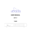
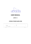
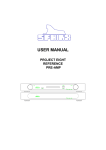
SPHINX REMOTE CONTROL
This single Sphinx Remote Control lets you control
all functions: not only of the Project Fifty but of all
other Sphinx equipment.
Only the following buttons and indications on the
Remote apply to the Project Fifty (the others will not
function):
Buttons
1. TUNER: To select the tuner. All buttons pressed
hereafter will control only the tuner functions
2. 1 - 0: With these numbered buttons you may
select each of the 99 memories or input a
station's frequency directly. To input a two digit
number (e.g. 12): quickly hit the corresponding
buttons ('1' and '2').
3. TUNING: These knobs let you change values in
each of the three display modes FREQ, MEM
and RDS (works like the VALUE knob).
4. BAND: This button has the same function as the
FM/AM button (7) on the front panel.
5. MUTE/MONO: This button has the same function
as the STEREO/MONO button (3) on the front
panel.
6. STOP: This button has the same function as the
ENTER button (9) on the front panel.
7. PAUSE: To switch the detailed Signal Level
Meter display on and off.
8. PLAY: This button has the same function as the
MAN/AUTO button (8) on the front panel.
9. SETUP: This button has the same function as
the SETUP button (4) on the front panel.
10. RW: This button has the same function as the
SELECT knob (1) on the front panel.
11. FF: This button has the same function as the
VALUE knob (12) on the front panel.
17
SPHINX
Project Fifty
Operation
The Sphinx Remote is used for several different
models and can therefore transmit different control
codes, depending on which model has been
selected with the select buttons (1.).
Important: Always press the TUNER button before
you send a command (even if you only have one
Sphinx component).
If not, it is possible that although the Remote will
send a signal nothing happens because the
transmitted signal is not 'recognised' by the
component.
Indoors the Remote may be used up to a distance of
7 meter, provided there is no strong sunlight in the
room and if you aim the Remote at the component.
Batteries
The two batteries have a life span of approx. one
year during normal use, but shorter when used more
intensely.
Replacement batteries: 1.5 V, model AAA. You may
also use rechargeable 1.5 V batteries.
Do not leave the battery compartment empty for
more than 30 minutes or else all information in
memory will be erased!
Note: Position the new batteries exactly as shown in
the illustration at the bottom of the battery
compartment, otherwise the remote control will not
work!
Encountering problems...
Always aim the Remote straight at the front panel of
the component, the maximum offset angle is 30°.
Component reacts differently than expected or
not at all
Selecting without switching
Wrong component selected
Select the correct one
Suppose for instance that you would like to select
the Tuner to Radio 4 without interrupting the CD
playback.
In that case you momentarily depress (not longer
than 0.5 sec) the 'TUNER' button and the '4' button.
The same procedure is used for the other system
components.
Only when you depress the select button longer than
0.5 sec, the system will select a different signal
source (in our example you will then hear the Tuner
playback).
Component or Remote does
not function
Check component with
it's original remote
Batteries of remote empty
Use new batteries
How to operate the Remote Control with the different
Sphinx components will be explained in the
corresponding User Manual of each component.
18
SPHINX
CARE AND MAINTENANCE
Clean the exterior with a soft, lint-free, anti-static
cloth. Do not use force while wiping the surface.
To remove difficult stains use a few drops of
detergent on a moist cloth, sweep carefully and wipe
dry afterwards.
Project Fifty
Do not use polishing or cleaning agents: they
may damage the sensitive finish.
Do not use aerosol cleaning agents.
Most contain solvents which might actively react and
damage the acrylic finish.
If some scratching occurs, please first consult your
Sphinx dealer. He can give you advice about
possible solutions.
TECHNICAL SPECIFICATIONS
FM section
Sensitivity, mono at (S+N)/N = 30 dB
mono at (S+N)/N = 50 dB
stereo at (S+N)/N = 50 dB
Dynamic selectivity
(mono + stereo) (Wide / Narrow)
Harmonic distortion, (mono/stereo)
(S+N)/N (IHF-A), (mono/stereo)
Channel separation
Tuning accuracy, automatic / manual
Special functions
Antenna inputs, 75 ohm
87.5 – 108.0 MHz
11 dBf (1 µV )
26 dBf (6 µV)
42 dBf (35 µV)
AM section, automatic tuning
manual tuning
Antenna input
Preset memories
522 – 1611 kHz
522 – 1611 kHz
2x spring-loaded clamp
99 (FM antenna + FM cable + AM)
Audio section
outputs
level
impedance
cinch: unbalanced / XLR: balanced
1.1 V (0.8 dBV) / 2.2 V (6.8 dBV)
50 ohm
/ 100 ohm
Power consumption
Dimensions (h x w x d)
Weight
20 W (11 W standby)
68 x 482 x 328 mm
13.5 kg
60 / 80 dB
<0.11 / 0.12%
>58 / 59 dB
>49 dB
50 kHz / 50 kHz
RDS ready
Coax: for external antenna
Coax: for CABLE (with 10 dB attenuator)
* Measured at 1 kHz and 65 dBf (1 mV) antenna
signal unless otherwise stated
This unit conforms to the EMC interference regulations from the EU and to the CE standards.
This unit complies with safety regulation VDE 0860 and thus with international safety regulation IEC 65.
Technical specifications can be changed by SPHINX without prior notice if technical developments make this
necessary.
©2000 Audioscript BV
Version 2000-07-27 /1.2 (software 3.0)
19