1
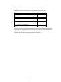
item 9 above. A similar set of tests is used for PSVs, except that
when testing against Hset, the i and j subscripts are switched as are
the > and < operators.
14. Flow
through an active PRV is maintained to force continuity at its
downstream node while flow through a PSV does the same at its
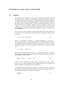
upstream node. For an active PRV from node i to j:
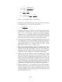
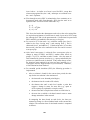
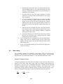
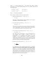
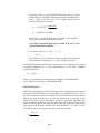
pij = 0
Fj = Fj + 108Hset
Ajj = Ajj + 108
This forces the head at the downstream node to be at the valve setting Hset.
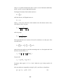
An equivalent assignment of coefficients is made for an active PSV except
the subscript for F and A is the upstream node i. Coefficients for open/closed
PRVs and PSVs are handled in the same way as for pipes.
15. For
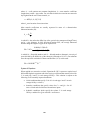
an active FCV from node i to j with flow setting Qset, Qset is
added to the flow leaving node i and entering node j, and is
subtracted from Fi and added to Fj. If the head at node i is less than
that at node j, then the valve cannot deliver the flow and it is treated
as an open pipe.
16. After
initial convergence is achieved (flow convergence plus no
change in status for PRVs and PSVs), another status check on
pumps, CVs, FCVs, and links to tanks is made. Also, the status of
links controlled by pressure switches (e.g., a pump controlled by the
pressure at a junction node) is checked. If any status change occurs,
the iterations must continue for at least two more iterations (i.e., a
convergence check is skipped on the very next iteration). Otherwise,
a final solution has been obtained.
17. For
extended period simulation (EPS), the following procedure is
implemented:
a. After a solution is found for the current time period, the time
step for the next solution is the minimum of:
•
the time until a new demand period begins,
•
the shortest time for a tank to fill or drain,
•
the shortest time until a tank level reaches a point that
triggers a change in status for some link (e.g., opens or
closes a pump) as stipulated in a simple control,
•
the next time until a simple timer control on a link kicks in,
•
the next time at which a rule-based control causes a status
change somewhere in the network.
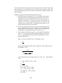
In computing the times based on tank levels, the latter are
assumed to change in a linear fashion based on the current flow
solution. The activation time of rule-based controls is computed
as follows:
192