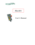
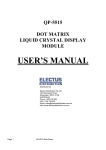
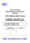
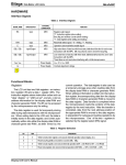
1
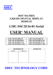
Customer Pole Display
SERIES 8035
Operation Manual
Version 1.0
8035 Series
User Manual
This equipment has been tested and found to comply with the limits for Class A
digital device. Pursuant to Part 15 of the FCC Rules. These limits are designed to
provide reasonable protection against harmful interference in aresidential
installation. This equipment generates, uses, and if not installed and used in
accordance with the instructions may cause harmful interference will not occur in a
particular installation. If this equipment does causeharmful interference to radio or
television reception, which can be determined by turning the equipment off and on.
The user is encouraged to try correct interference by one or more of the following
measures:
- Reorient or relocate the receiving antenna.
- Increase the separation between the equipment and receiver.
- Connect the equipment into an outlet on a circuit different from that to which the
receiver is connected.
- Consult the dealer or an experienced radio/TV technician for help. This booklet is
available from the U.S. government Printing Office, Washington, DC 20402, Stock
NO.004-000-00345-4.
CAUTION:
Any changes of modifications not
expressly approved by the grantee of this device
could void the user’s authority to operate the
equipment.
Operation is subject to the following two conditions:
(1) This device may not cause harmful interference.
(2) This device must accept any interference received including interference that
may cause undesired operation.
1
8035 Series
User Manual
Table of Contents:
Chapter 1
Introduction .............................................................................3
Chapter 2
Appearance ............................................................................4
Chapter 3
Before You Install.....................................................................5
Chapter 4
Installing Model 8035
4-1 RS-232 Interface.............................................................6
4-2 USB Interface..................................................................8
Chapter 5
Programming Commands........................................................9
Appendix I
Specifications.........................................................................11
Appendix II
Character Generator ROM Map.............................................12
2
8035 Series
Chapter 1
User Manual
Introduction
The 8035 multi language LCD customer display is an excellent tool for
transmitting transactions, advertising message, and customer greeting at POS
system(point-of-sale system). With adjustable tilt angles and visual swivel,
customer could freely set just right angle and pole height according to their
demand. The bright alphanumeric LCD display provides wide viewing angles, no
matter in close or short distance. 8035 LCD customer display also support multi
languages (Japan/English, Europe/English, Russia/English), let it application
of multi lingual environments. With ESC/POS command codes, 8035 can work
under any operation system and platform.
Features:
● Easy to read of blue background & white characters display.
● Six adjustable viewing angles and visual swivel design
● Multi language support: Japan/English, Europe/English, Russia/English
● USB/RS232 communication
● Built-in ESC/POS command codes
The develops 8035 OPOS firmware (OLE for retail POS), not only accordance
with Microsoft OPOS standard but also includes our exceptional functions. We
also simplify the complicated installation procedure of OPOS driver to one step
completion. In addition, we also provide 8035 OPOS test program for operator
easy learning and whole function test as well as compatible problem handling.
Therefore, 8035 could smoothly perform its unique features and perfectly work
with various OPOS environments.
OPOS Features:
● One-step installation
● Quick start
● Marquee show
● Blink light show
● Brightness adjustable
For Its high compatibility and convenience with other hardware, it is ideal for
applying to retail, hospitality, fast food, hotel, financial service and other
industrial application。Based on professional abilities, we have confidence to
optimize the customized product and suggest the private solution for clients.
3
8035 Series
User Manual
Chapter 2
Appearance
LCD Display
Cable Connector
JD-8035
4
8035 Series
Chapter 3
User Manual
Before You Install
This manual describes functions and usage of the Model 8035
customer pole display. The 8035 is a 2x20 alphanumeric customer
pole display designed with multi-languages for retail and other
industrial environments. Its outstanding features include high
quality liquid crystal display in blue & white color,USB & serial
interface are easy to use and powerful programming features.
The 8035 can also combine with any serial receipt printer.
Step 1: Turn Off Your Computer
By shutting off your computer, you will prevent any accidental damage to the
pole display and computer.
Step 2: Review Packing List
Please ensure that your pole display shipment is complete.
Model 8035 includes:
• 1 pcs 8035 pole display
• 1 pcs operation manual
• 1 pcs +12V DC power plate with internal power cable (for RS232)
• 1 pcs DC cable
• 1 pcs USB cable
• 1 pcs pole
NOTE: The last character of indicates Cable’s color.
Ex: W=White; B=Black
5
8035 Series
User Manual
Chapter 4
Installing Model 8035
This chapter describes the procedures for installing the
8035 pole display by RS-232 & USB interface.
4-1 .RS232 Interface.
Step 1: Turn off your computer
If you have not already done so, turn off your computer to avoid any accidental
damage to the pole display and computer.
Step 2: Bulid up your 8035
JD-8035
Touch POS 8802
DB-9F
RJ-45
8035 Customer Pole Display
RS-232C Installation
6
8035 Series
User Manual
Step 3: Decide on power access
The RS-232 connection requires power +12V DC. This may be provided through an
internal connection in your computer or through an external connection to a 110/220V
adapter. The components for an internal connection are provided.
Step 4: Using internal power source
Refer to the installation diagram as below. Remove the access cover to your computer.
Mount the +12V DC power plate on an available expansion slot in the back of your
computer. Attach the 4-pin male connector to the open female connector of the same
type in your computer.Alternatively, an internal power source may be available already
if the com port on your computer or terminal matches the 8035 pin assignment.
.
Step 5: Connect to your computer
Connect the RS-232 connector to the male equivalent com port on your computer
or terminal. Provide power to the DC jack on the DB9F connector using
either a cable connection to the +12V DC power plate or an external adapter.
Step 6: Turn on your computer
Turn on your computer. It should boot up normally.
The pole display will show a self-diagnostic status and then the display will be
blank.
Step 7: Turn to Chapter 5
You are now ready for operation; please refer to Chapter 5 for programming to
meet the specific requirement of your application environment.
7
8035 Series
User Manual
4-2 USB Interface
Step 1: Bulid up your 8035
JD-8035
Touch POS 8802
USB B
USB A
8035 Customer Pole Display
USB Installation
Step 2: Connect to your computer
Connect the USB connector to the usb port on your computer.
Step 3: Refer to RS-232 configuration
Please refer to RS-232 configuration step 3 and following steps.
(USB 2.0 user access 8035 via virtual com port)
8
8035 Series
Chapter 5
User Manual
Programming Commands
There is a programming mode available for model 8035 with ESC/POS mode. In this Chapter,
we will use ESC/POS mode for multi-languages, Please refer to Appendix for details.
The basic function of the 8035 display is comparable to the display programming by
your software should be as easy. You only need open the COM-port on which the
display has been connected from you. Then, you just needs send the character what you
want to display on 8035 directly via the COM port. Please following the USB/RS232
parameters to use as below:
9600 Baud, No Parity, 8 Data Bits, 1 Stop bit
In Basic, you would initialize the interface as follows:
OPEN “COMx: 9600, N, 8, DS0” FOR OUTPUT AS #1
(x=number of the COM port you are using for the display)
And you would print something to the display using the PRINT command:
PRINT#1, “Hello World!”
In the end, you can close the interface:
CLOSE #1
In other programming languages, the commands for serial output shall be
different, but they will work in a similar way. For some compilers, you will need
an extra toolbox, that offers you usb routines. Please refer to your
compiliers/interpreters manual for more details.
Example:
OPEN “COMx: 9600, N, 8, 1, DS0” FOR OUTPUT AS #1
PRINT #1, “Hello World!”
CLOSE #1
9
8035 Series
User Manual
Programming using DOS routines
You can also generate a display output using the simple DOS routines.
Example:
MODE COMx: 9600, N, 8, 1
ECHO Hello! >COMx:
Control characters and special functions
For special display functions, there are some commands which will be
explained in this chapter. Some of the commands consist of one
ASCII-CTRL-code, others are command strings, introduced by ESC.
If a command needs additional parameters, please do not forget to use ASCII
format for the parameter. That means, if the parameter is 0 (zero), then you
have to transmit the ASCII code “0” (=CHR$(48) in Basic; 48 is the decimal
position of the “0” character in the ASCII code table). But please consider that
only ONE byte is allowed for each parameter. That is why you cannot transmit
two digit numbers. In this case, just add the number you want to transmit as
parameter 48 and transmit the corresponding character. For example, if you
want to transmit the parameter 11, you have to send
CHR$(11+48)=CHR$(59)=“;”. Attention: For some other commands, only
BYTE values are allowed as parameter. For those, you directly send the
corresponding character code without adding 48 (e.g. CHR$(11) for 11). For
details, please refer to the individual command code descriptions.
Example: Set the cursor to the last position in the display area
WRONG:
PRINT #1, CHR$(27)+“=”; :REM command ESC =
PRINT #1, 19;1 :REM parameter column 19, line 1
CORRECT:
PRINT #1, CHR$(27)+“=”;
PRINT #1, CHR$(48+19)+“1” :REM or CHR$(48+19)+CHR$(48+1)
Below is a list of command sequences for user to design an interface to the
8035 customer pole display.
Please note that pole display is default with 9600 bps baud rate, no parity, 8
data bits, 1 stop bit.
10
8035 Series
Appendix I
NO
1
2
3
4
5
6
7
8
9
10
User Manual
Specifications
Item
Display method
LCD type
Backlight mode
Brightness
Display color
Adjustable angle
Viewing angle
Numberof character
Character size
Character font
Descriptions
Liquid crystal display
STN Blue mode
LED backlight
600 cd/m2
Blue (back color) and White (character color)
Swivels 360° and Tilt 45° Angles
0– 45 degrees
20 columns x 2 lines
5mm(w) x 10mm (H) , 5x7 dot
2 x 20 dot matrix by alpha numeric
Japan / English
11 Language
Europe/ English
Russian / English
USB 2.0 user access 8035 via virtual Comport
12 Interface
RS-232 with DC jack
13 Software Programming ESC/POS OPOS (OLE for Retail POS)
5V DC from HOST USB port
14 Power Requirement
12V DC from RS232 port
15 Total dimensions
214 (W) x 70 (H) x 40 (D) mm
16 Optional Pole Height
140mm or 280mm
17 Approximate Weight
950g
18 Material
ABS Plastic & ABS Plastic with Metal
19 Colors
Dark Gray or White
20 Operating temperature 5 - 45℃
21 Operating Humidity
30% - 85%
22 Storage Temperature
-10 - 55℃
23 Storage Humidity
10% - 85%
11
8035 Series
User Manual
Appendix II
Character Generator
ROM Map
1. 8035(Japan/English) Font Table
Lower
4 bit
Higher
4 bit
0000
xxxx0000
CG
RAM
(1)
xxxx0001
(2)
xxxx0010
(3)
xxxx0011
Lower 4-bit (D0-D3) of Character Code (Hexadecimal)
CHARACTER PATTERN CHART(5x7DOTS+CURSOR)
0010 0011 0100 0101 0110 0111 1010 1011 1100 1101 1110 1111
(4)
xxxx0100
(5)
xxxx0101
(6)
xxxx0110
(7)
xxxx0111
xxxx1000
(1)
xxxx1001
(2)
xxxx1010
(3)
xxxx1011
(4)
xxxx1100
(5)
xxxx1101
(6)
xxxx1110
(7)
xxxx1111
12
8035 Series
User Manual
2. 8035(Europe/English) Font Table
Upper
4 bir
Lower
4 bir
LLLL LLLH LLHL LLHH LHLL LHLH LHHL LHHH HLLL HLLH HLHL HLHH HHLL HHLH HHHL HHHH
LLLL
(00H)
LLLH
(01H)
LLHL
(02H)
LLHH
(03H)
LHLL
(04H)
LHLH
(05H)
LHHL
(06H)
LHHH
(07H)
HLLL
(08H)
HLLH
(09H)
HLHL
(0AH)
HLHH
(0BH)
HHLL
(0CH)
HHLH
(0DH)
HHHL
(0EH)
HHHH
(0FH)
13
8035 Series
User Manual
3. 8035(Russian/English) Font Table
Lower
4 bit
Higher
4 bit
0000
xxxx0000
CG
RAM
(1)
xxxx0001
(2)
xxxx0010
(3)
xxxx0011
Lower 4-bit (D0-D3) of Character Code (Hexadecimal)
CHARACTER PATTERN CHART(5x7DOTS+CURSOR)
0010 0011 0100 0101 0110 0111 1010 1011 1100 1101 1110 1111
(4)
xxxx0100
(5)
xxxx0101
(6)
xxxx0110
(7)
xxxx0111
xxxx1000
(1)
xxxx1001
(2)
xxxx1010
(3)
xxxx1011
(4)
xxxx1100
(5)
xxxx1101
(6)
xxxx1110
(7)
xxxx1111
14
8035 Series
User Manual
15