1
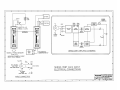
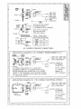
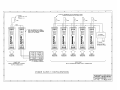
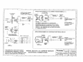
User's Manual: Series 350T
AC Current Input (External Sensor), DC-Powered Transmitters
INTRODUCTION:
Table of Contents
Page
Introduction
Description
Specifications
Installation
Calibration
General Maintenance
1
1
2
3
4
5
List of Drawings
These instructions cover the model types listed in Table 1 below.
Supplementary sheets are attached for units with special options or
features.
Table 1:
A. Model Number Format :
1
350T-Input-Output-Mounting-Certification
1
B. Typical Model Number: 350T-CACX-Y-DIN-NCR
Page
Electrical Connections: CACX Input (4501-382)
Electrical Connections: AC Current Sensor (4501-380)
Dimensions: DIN Rail Mounting (4501-252)
Electrical Connections: Power Supplies (4501-254)
Series
350T
6
7
8
9
-Input
-CACX
-Output
-Y
-V0
-V5
-Mounting
-DIN
-Certification
-NCR
2
-Approval
Notes (Table 1):
1. All units are factory calibrated (No “-C” suffix needed).
2. Consult the factory for current information on agency (e.g.
Canadian Standards Association, etc.) approvals.
DESCRIPTION:
IMPORTANT SAFETY CONSIDERATIONS
It is very important for the user to consider the possible adverse
effects of power, wiring, component, sensor, or software failures in
designing any type of control or monitoring system. This is
especially important where economic property loss or human life is
involved. It is important that the user employ satisfactory overall
system design. It is agreed between the Buyer and Acromag, that
this is the Buyer's responsibility.
These DC-powered transmitters are used in conjunction with an
external AC Current Sensor to condition an AC current input signal
and convert this signal to a process current or voltage output. An
AC Current Sensor is supplied with each transmitter (a highly
accurate toroidal instrument transformer). The AC Current Sensor is
fully insulated and designed to mount near the source of the AC
current. It transmits a safe, low-level DC milliamp signal to the
transmitter. Both the AC Current Sensor and transmitter are
isolated for up to 250V AC, or 345V DC peak, between input and
output. The transmitter Output (-) and DC power (-) share a
common terminal. This transmitter is DIN-rail mounted. See
Drawing 4501-382 for a simplified schematic.
The benefits to using an external sensor (external from the
transmitter enclosure) include the following:
1. Low losses: It is not practical to run AC currents over long
distances because of significant resistance voltage drops at
high currents. However, a low level DC milliampere signal is
output from the AC Current Sensor and can be transmitted
safely over long distances, allowing the transmitter to be
remotely located some distance from the AC power wiring.
Acromag, Inc.
30765 Wixom Road, P.O. Box 437
Wixom, Michigan 48393-7037, USA
Tel: (248) 624-1541
FAX: (248) 624-9234
2. Safety: The AC Current Sensor's output leads can be open
or short circuited and these conditions do not affect the AC
current loop or cause damage to the sensor. Likewise, the
wires connecting the AC Current Sensor to the transmitter
can be easily removed from the transmitter's input terminals
without concern or hazard.
Copyright 1994, Acromag, Inc., Printed in the USA.
Data and specifications are subject to change without notice.
8500-503-A94A000
-1-
Series 350T User's Manual
AC Current Input (External Sensor)
___________________________________________________________________________________________
MODEL/SERIES: 350T- (Color coded with a white label)
3. Ease of Calibration: The AC current input range can be
easily scaled in the field by changing the number of primary
turns at the sensor, with no additional calibration required.
The transmitter is factory calibrated and can be used with
any AC Current Sensor (Acromag Model 5020-350). The
AC current input span is a simple function of the number of
primary turns placed on the AC Current Sensor and
transmitter calibration is not affected. Refer to Applications
"A" and "B" of Drawing 4501-380. This method of changing
ranges is much easier, more accurate, and convenient.
SENSOR
PRIMARY TURNS
4
1
2
10
20
AC CURRENT
INPUT RANGE
0 to 5 Amps AC
0 to 20 Amps AC
0 to 10 Amps AC
0 to 2 Amps AC
0 to 1 Amps AC
INPUT (Sensor and Transmitter):
AC Current Sensor (5020-350): One sensor is supplied with each
Model 350T-CACX transmitter. The sensor is a highly accurate
toroidal instrument transformer used to convert an AC current
signal to a low level DC milliampere signal (0 to 11.17mA). The
input AC current range is a simple function of the number of
turns placed on the AC Current Sensor (see table below).
The user configures the AC current sensor with the required
number of primary turns to obtain the desired input span.
TRANSMITTER
OUTPUT (350T)
4-20mA or VDC
4-20mA or VDC
4-20mA or VDC
4-20mA or VDC
4-20mA or VDC
AC CURRENT
INPUT RANGE
Series 350T transmitters are designed as another functional
component that provides the user with a modular approach to the
varied applications in the field. Other 350T transmitters are
available to condition DC voltage, DC current, frequency,
thermocouple, RTD, slidewire/potentiometer, and AC voltage inputs.
The Series 350T complements the Acromag Series 250T two-wire
transmitter line, providing the same input conditioning for three-wire
applications. That is, Series 350T transmitters require a separate
power supply connection, while the output signal and DC power
share a common lead. For AC powered applications, see the
Acromag Series 450T. The small package size, low power
requirements, and wide supply range offer maximum flexibility to the
system designer. As a three-wire DC powered device, it can be
used in critical applications that require the use of redundant
supplies. The Series 350T includes reverse polarity protection,
current limiting, and operates from a single 10V to 36V DC supply.
In applications requiring only a single transmitter, the 350T can use
available DC power, or it can be wired to an optional Series 35PS
power supply module. The Series 35PS power supply module
receives it's power from either 115V AC, 230V AC, or 10-36V DC.
Applications requiring multiple transmitters at a single location can
more efficiently share a single DC supply. The modular approach of
this design and companion Acromag flat-pack modules allows
additional transmitters, input modules, isolators, and alarms to be
easily integrated, as required.
Function: This family of isolated, DC-powered, sensor/transmitter
pairs condition an AC current input and convert this signal to a
process current or voltage output. The sensor is designed to be
field mounted near the AC current it is measuring and transmits
a low level DC milliamp signal to the transmitter’s input. The
sensor and transmitter are both isolated between input and
output. The transmitter output (-) and DC power (-) share a
common terminal in a 3-Wire configuration. The transmitter
zero and span adjustments utilize 22-turn pots accessible from
the front of the unit. This transmitter is DIN-rail mounted.
0 to 5 Amps AC
4
SENSOR OUTPUT
(RED/BLACK
WIRES)
0 to 11.17mA DC
0 to 20 Amps AC
0 to 10 Amps AC
0 to 2 Amps AC
0 to 1 Amps AC
1
2
10
20
0 to 11.17mA DC
0 to 11.17mA Dc
0 to 11.17mA DC
0 to 11.17mA DC
The output wires of the sensor are polarized: the Red wire is (+)
plus and Black wire is (-) minus. Normally, these output wires
are attached to one end of a cable (user supplied) and the other
end connects to the transmitter's input (+) and (-) terminals.
Input Burden: A function of the wire gauge resistance used for the
primary turns.
Input Overload: The AC Current Sensor withstands overloads as
follows:
•
•
•
20 times full-scale for 0.01 second
10 times full-scale for 0.1 second
5 times full-scale for 1.0 second
AC Current Sensor to Transmitter Wiring Distance: 400 feet
maximum for 18 AWG wire gauge. Other wire gauges can be
used as long as the resistance of both wires is less than 5.0 Ω.
Transmitter (350T-CACX):
Input wiring is inserted in the bottom of the unit, while output and
power wiring is inserted at the top of the unit. Screws to secure the
wiring are located on the front panel. Connectors are screw-clamp
type and accept wire size up to 14 AWG.
SPECIFICATIONS:
PRIMARY
TURNS
-CACX: Input is DC milliamperes from the AC Current Sensor
supplied with the transmitter. The Input to the transmitter
is 0 to 11.17mA DC (output of the AC Current Sensor).
This signal represents 0 to 5 Amps AC with 4 primary
turns at the input to the AC Current Sensor, or any other
AC current range (a function of primary turns). Changing
the number of primary turns does not change the
calibration of the transmitter, only the input range is
affected. The output and DC power share a common
terminal (3-Wire connection).
Isolation (Both Sensor and Transmitter): The input circuit is
electrically isolated from the output and power circuits
(transmitter), allowing the input to operate at up to 250V AC, or
354V DC off ground, on a continuous basis (will withstand
1500V AC dielectric strength test for one minute without
breakdown). This complies with test requirements outlined in
ANSI/ISA-S82.01-1988 for the voltage rating specified.
-2-
Series 350T User's Manual
AC Current Input (External Sensor)
___________________________________________________________________________________________
OUTPUT: Process Current or Voltage output. The output shares a
common with the power supply. Voltage outputs are designed
to provide true voltage output, with zero volts included, and to be
stable with capacitive loads.
-Y : 4 to 20mA DC (see Load Resistance Range Equation)
-V0: 0 to 10V DC into 10,000 ohms or greater
-V5: 0 to 5V DC into 5,000 ohms or greater
Bandwidth: -3dB at 2 Hz, typical (transmitter only).
Response Time: For a step input, the output reaches 98% of its
transition in 300ms, typical (transmitter only).
Noise Rejection:
Common Mode: Better than 130dB at 60 Hz, typical, 100 ohm
unbalance (transmitter only).
Normal Mode: Not applicable.
Load Resistance Range Equation (-Y output option): The
maximum load resistance for 20mA compliance is a function of
input supply voltage as follows:
RFI Resistance: Less than ± 0.5% of output span effect with RFI
field strengths up to 10V/meter at frequencies of 27MHz,
151MHz, and 467MHz.
R-Load (Maximum) = (Minimum VDC supply - 2.5V) / 0.02A
At 10.0V DC supply, R-Load = 0 to 375 ohms
At 12.5V DC supply, R-Load = 0 to 500 ohms
At 15.0V DC supply, R-Load = 0 to 625 ohms
At 24.0V DC supply, R-Load = 0 to 1075 ohms
EMI Resistance: Less than ±0.25% of output span effect with
switching solenoids or commutator motors.
Output Limiting: Voltage units: 150% of full scale output, nominal;
Current units: 125% of full-scale output, nominal.
Surge Withstand Capability (SWC): Input/Output terminations are
rated per ANSI/IEEE C37.90-1978. Unit is tested to a
standardized test waveform that is representative of surges
(high frequency transient electrical interference), observed in
actual installations.
Output Ripple: Less than ±0.1% of the maximum output span.
Construction:
AC Current Sensor: Epoxy dipped and baked.
Circuit Boards: Military grade FR-4 epoxy glass circuit board.
Circuit Board Coating: Fungus resistant acrylic conformal coat.
Terminals: Compression type, wire size 14 AWG maximum.
Mounting Position: Position insensitive.
Case: Self-extinguishing NYLON Type 6.6 polyamide black
thermo-plastic UL94 V-2, General Purpose, NEMA Type 1
enclosure.
Power: An external DC power supply is required between the
output (P) and (-) terminals. Transmitter current is for rated
supply inputs, full-scale output, and no-load on voltage output
units. Diode on transmitter provides reverse polarity protection.
CAUTION: Do not exceed 36V DC peak supply voltage, to
avoid damage to the transmitter.
A.
Process Current Output (-Y): +10.0V to 36.0V DC, 30mA
(35mA at current limit).
B. Voltage Output (-V0): +12.5V to 36.0V DC, 9mA maximum.
C. Voltage Output (-V5): +10.0V to 36.0V DC, 9mA maximum.
Power Supply Effect:
DC Volts: less than ±0.001% of output span per volt DC, for
rated power supply variations.
60/120 Hz ripple: less than ±0.01% of span per volt peak-topeak of power supply ripple.
Reference Test Conditions: Input: 0 to 5 Amps AC, 60Hz. (4 turn
primary); Output (-Y units): 4-20mA DC (500 ohm load); Output
(-Vx units): 0-10V DC into 10K ohms or greater; Ambient 77oF
(25oC); +15V DC supply.
Accuracy: Better than ±0.5% of calibrated span. This error
includes the combined effects of transmitter repeatability,
hysteresis, terminal point linearity, adjustment resolution and AC
Sensor error.
Ambient Temperature Range: -13oF to 185oF (-25oC to 85oC).
Ambient Temperature Effect: Less than ± 0.01% of output span
per oF (± 0.018% per oC) over the ambient temperature range
for reference test conditions. Specification includes the
combined effects of zero and span over temperature.
MOUNTING (Transmitter):
-DIN: General Purpose Housing, DIN-Rail Mount - "G" & "T"
rails. "G" Rail (32mm), Type EN50035; "T" Rail (35mm),
Type EN50022. Refer to Drawing 4501-252 for outline
and clearance dimensions.
Shipping Weight: 1 pound (0.45 Kg) packed.
CERTIFICATION: Consult the factory for current information on the
availability of agency (e.g. Canadian Standards Association,
Factory Mutual, etc.) approvals.
-NCR: No Certification Required.
INSTALLATION:
The transmitter is packaged in a general purpose enclosure.
Use an auxiliary enclosure to protect against unfavorable
environments and locations. Maximum operating ambient
temperatures should be within -13 to 185oF (-25 to 85oC) for
satisfactory performance. Factory calibrated units are ready for
installation. Connect as shown in Drawing 4501-380 and 4501-382.
To verify calibration, refer to the "CALIBRATION" section.
Mounting: Mount transmitter assembly - refer to Drawing 4501-252
for mounting and clearance dimensions.
-3-
Series 350T User's Manual
AC Current Input (External Sensor)
___________________________________________________________________________________________
DIN Rail Mounting: Use suitable fastening hardware to secure
the DIN rail to the designated mounting surface. A transmitter,
can be mounted to either the "T" or "G" Rail. Installation of the
transmitter to the rail depends on the type of DIN rail used (see
Drawing 4501-252). Units can be mounted side-by-side on 1.0inch centers, if required.
DANGER: If the AC Current Sensor is used with an AC
Current Transformer (C.T.), disconnect power to the
C.T., or short the output of the C.T., before removing
the wire going through the AC Current Sensor. If this is
not done, an open-circuited C.T. will generate high
voltages (hazardous) and possible C.T. damage.
Electrical Connections:
The sensor output wires should be connected to the
extension cable (wires) using wire nuts, or equivalent.
Sensor output wires are color coded RED (+) and
BLACK (-), proper polarity must be observed.
The wire size used to connect the unit to the control system is
not critical. All terminal strips can accommodate wire from 1426 AWG. Strip back wire insulation 1/4-inch on each lead
before installing into the terminal block. Input wiring may be
shielded or unshielded twisted pair. Output wires should be
twisted pair. Since common mode voltages can exist on signal
wiring, adequate wire insulation should be used and proper
wiring practices followed. It is recommended that the output and
power wiring be separated from the signal wiring for safety, as
well as for low noise pickup.
1. Power: Connect DC power supply per Drawing 4501-382.
Power supply voltage is not critical and normally should be
from 10.0V to 36V DC. The supply voltage must not exceed
36 Volts, even instantaneously, and must be adequate to
furnish full-scale current or voltage to the load. Variations in
power supply voltage above the minimum required, or
variations in load resistance have negligible effect on
transmitter accuracy. Refer to "POWER" in the preceding
SPECIFICATIONS section for current requirements. The
minus (-) power supply lead and the minus (-) output lead
share a common terminal. This device includes input
current limiting and reverse polarity protection. Refer to
Drawing 4501-254 for other power supply configurations.
2. Output: Connect output per connection diagram (see
Drawing 4501-382). Load range is a function of the
module's output type; refer to "Output" in the preceding
"SPECIFICATIONS" section. The output shares a common
with the power supply.
3. Grounding: The transmitter housing is plastic and does
not require an earth ground connection.
4. Input: The AC Current Sensor is isolated and can be used
in AC circuits up to 250V AC, 50 to 60 Hz. It is designed
to be mounted at the source of the AC current to be
measured. The sensor outputs a low-level DC milliampere
signal, allowing the transmitter to be mounted remote from
the AC signal using small gauge wires. The sensor's output
(Red/Black) wires can be shorted, open-circuited, or
removed from the transmitter’s input terminals, without
hazard to personnel or the AC Current Sensor.
A. AC Current Sensor: Per the Input Range chart in the
Specifications Section, loop the required number of
turns through the toriod for the full-scale range needed
in your application. Use the cable tie provided to
mechanically secure the sensor. Refer to Drawing
4501-380.
B. Transmitter: Connect the Current Sensor output leads
to the transmitter: Red (+) to the Transmitter plus (+)
terminal, Black (-) to the Transmitter minus (-) terminal.
WARNING: The input to the transmitter can only come
from the AC Current Sensor output wires (Red/Black). If
AC current is directly attached to the transmitter input
terminals, the transmitter will be destroyed.
NOTE: The transmitter's input circuit is electrically
isolated from the output/power circuit for voltages up to
250V AC ,or 354V DC off ground, on a continuous
basis. In this application, it is recommended that the
minus (-) transmitter input terminal be connected to an
earth ground. The connections between the AC Current
Sensor would be floating if not grounded. Grounding
eliminates the risk of high common-mode voltages from
showing up on the wires and reduces noise pickup.
CALIBRATION:
All sensors and transmitters are checked and calibrated for
proper performance at the factory before they are shipped. The
calibration example below is provided for reference.
Adjustment Procedure:
Connect the transmitter as shown in Calibration Connection
Drawing 4501-382. To simplify transmitter adjustment, it is
recommended that a DC current method be used. For best results,
the signal current source should be adjustable over the entire input
range of the unit and settable to an accuracy of 0.1% or better.
Load the module within the limitations listed in "Output" of the
preceding "SPECIFICATIONS" section. The output voltage or
current must be measured to 0.1% accuracy or better for proper
results.
The Zero and Span adjustments are accessible from the front
panel of the transmitter (see Drawing 4501-382). The screwdriver
blade used to adjust the potentiometers should not be more than 0.1
inch (2.54mm) wide. There are no internal jumpers or switches to
configure.
-4-
Series 350T User's Manual
AC Current Input (External Sensor)
___________________________________________________________________________________________
Transmitter - Calibration Example:
MODEL : 350T-CACX-VO-DIN-NCR
Output : 0 to 10V DC.
Input : 0 to 11.17mA DC (Note: The DC current range that
the AC Current Sensor provides to the transmitter is
independent of the number of primary turns).
1. Set the input source to 0.000mA DC. Adjust the Zero (Z) pot
until the output reads 0.000V DC.
2. Set the input source to 11.17mA DC. Adjust the Span (S) pot
until the output reads 10.000V DC.
3. Repeat steps 1 and 2 until the readings converge. The
instrument is now calibrated. Several mid-point values should
also be checked to verify proper operation of the transmitter.
GENERAL MAINTENANCE:
The transmitter contains solid-state components and requires no
maintenance, except for periodic cleaning and calibration
verification. When a failure is suspected, a convenient method for
identifying a faulty transmitter is to exchange it with a known good
unit. It is highly recommended that a non-functioning transmitter be
returned to Acromag for repair, since Acromag makes use of tested
and burned-in parts, and in some cases, parts that have been
selected for characteristics beyond that specified by the
manufacturer. Further, Acromag has automated test equipment that
thoroughly checks the performance of each transmitter.
-5-
Supplemental Instructions
MODEL 5020-350, AC Current Input (External Sensor) Modules
IMPORTANT SAFETY CONSIDERATIONS
IMPROPER CONNECTIONS, OR CONNECTING TO MODULE INPUTS FROM ANYTHING OTHER THAN THE SUPPLIED AC CURRENT
SENSING TRANSFORMER COULD CAUSE PERMANENT DAMAGE TO THE MODULE AND CREATE A SAFETY HAZARD TO THE USER.
PLEASE READ THE FOLLOWING AND REFER TO THE CONNECTION DRAWINGS ON THE REVERSE SIDE BEFORE INSTALLATION.
This AC current input module is used in conjunction with an external AC Current Sensor to pre-condition the AC current input signal. The sensor is
a highly accurate toroidal instrument transformer used to convert the AC current signal to a safe, low-level, DC milliampere signal (0 to 11.17mA).
The module only accepts the isolated low-level signal produced by the AC current sensing transformer and cannot be connected directly to the
source of AC power without damage or safety risk. The AC Current Sensor is fully insulated and designed to mount near the source of the AC
current. The input AC current range is a simple function of the number of turns placed on the AC Current Sensor (see the table below). The
benefits to using an external sensor (external from the module enclosure) include the following:
•
•
•
AC CURRENT INPUT RANGE
0 to 20 Amps AC
0 to 10 Amps AC
0 to 5 Amps AC
0 to 2 Amps AC
0 to 1 Amps AC
SENSOR OUTPUT (RED/BLACK WIRES)
0 to 11.17mA DC
0 to 11.17mA DC
0 to 11.17mA DC
0 to 11.17mA DC
0 to 11.17mA DC
Low losses: It is not practical to run AC currents over long distances because of significant resistance voltage drops at high currents. The
low-level DC milliampere signal output from the AC Current Sensor can be transmitted safely over long distances, allowing the transmitter to be
remotely located from the AC power wiring.
Safety: The AC Current Sensor's output leads can be open or short circuited and these conditions do not affect the AC current loop or cause
damage to the sensor. Likewise, the wires connecting the AC Current Sensor to the transmitter can be easily removed from the transmitter's
input terminals without concern or hazard.
Ease of Calibration: The AC current input range can be easily scaled in the field by simply changing the number of primary turns at the
sensor, with no additional calibration required. That is, the AC current input span is a simple function of the number of primary turns placed on
the AC Current Sensor and sensor/transmitter calibration is not affected by this. Refer to Applications "A" & "B" of the Drawings on the back.
SENSOR PRIMARY TURNS
1
2
4
10
20
The AC Current Sensor is isolated and can be used in AC circuits up to 250V AC, 50 or 60 Hz. It is designed to be mounted at the source of the
AC current to be measured. The module can be located remotely from the AC signal and wired using small gauge wire. The sensor's output wires
can be shorted, open-circuited, or removed from the transmitter’s input terminals, without hazard to personnel or the AC Current Sensor.
DANGER: If the AC Current Sensor is used with an AC Current Transformer (C.T.), disconnect power to the C.T., or short the output of the C.T.,
before removing the wire going through the AC Current Sensor. If this is not done, an open circuited C.T. will generate high voltages (hazardous)
and possible C.T. damage.
The output wires of the sensor are polarized: the Red wire is (+) plus and the Black wire is (-) minus. Normally, these output wires are attached to
one end of a cable (user supplied) and the other end connects to the module’s input. Connect the Current Sensor output leads to the module input
by connecting Red (+) to the module’s plus (+) terminal, and Black (-) to the module’s minus (-) terminal. Proper polarity must be observed.
WARNING: The input to the module can only come from the AC Current Sensor output wires (Red/Black). If AC current is directly attached to the
module’s input terminals, the module will be destroyed and safety compromised.
8500-239-B96L001
For most applications, it is recommended that the minus (-) module input terminal be connected to an earth ground. The connections between the
AC Current Sensor would be floating if not grounded. Grounding eliminates the risk of high common-mode voltages from showing up on the wires
and reduces noise pickup.
ACROMAG, INCORPORATED
30765 South Wixom Road, PO Box 437, Wixom, MI 48393-7037,USA
Tel: (248) 624-1541, FAX: (248) 624-9234
Copyright 1988, 1994, Acromag, Inc., Printed in the USA.
Data and specifications are subject to change without notice
Supplemental Instructions
MODEL 5020-350, AC Current Input (External Sensor) Modules
IMPORTANT SAFETY CONSIDERATIONS
IMPROPER CONNECTIONS, OR CONNECTING TO MODULE INPUTS FROM ANYTHING OTHER THAN THE SUPPLIED AC CURRENT
SENSING TRANSFORMER COULD CAUSE PERMANENT DAMAGE TO THE MODULE AND CREATE A SAFETY HAZARD TO THE USER.
PLEASE READ THE FOLLOWING AND REFER TO THE CONNECTION DRAWINGS ON THE REVERSE SIDE BEFORE INSTALLATION.
This AC current input module is used in conjunction with an external AC Current Sensor to pre-condition the AC current input signal. The sensor is
a highly accurate toroidal instrument transformer used to convert the AC current signal to a safe, low-level, DC milliampere signal (0 to 11.17mA).
The module only accepts the isolated low-level signal produced by the AC current sensing transformer and cannot be connected directly to the
source of AC power without damage or safety risk. The AC Current Sensor is fully insulated and designed to mount near the source of the AC
current. The input AC current range is a simple function of the number of turns placed on the AC Current Sensor (see the table below). The
benefits to using an external sensor (external from the module enclosure) include the following:
•
•
•
Low losses: It is not practical to run AC currents over long distances because of significant resistance voltage drops at high currents. The
low-level DC milliampere signal output from the AC Current Sensor can be transmitted safely over long distances, allowing the transmitter to be
remotely located from the AC power wiring.
Safety: The AC Current Sensor's output leads can be open or short circuited and these conditions do not affect the AC current loop or cause
damage to the sensor. Likewise, the wires connecting the AC Current Sensor to the transmitter can be easily removed from the transmitter's
input terminals without concern or hazard.
Ease of Calibration: The AC current input range can be easily scaled in the field by simply changing the number of primary turns at the
sensor, with no additional calibration required. That is, the AC current input span is a simple function of the number of primary turns placed on
the AC Current Sensor and sensor/transmitter calibration is not affected by this. Refer to Applications "A" & "B" of the Drawings on the back.
SENSOR PRIMARY TURNS
1
2
4
10
20
AC CURRENT INPUT RANGE
0 to 20 Amps AC
0 to 10 Amps AC
0 to 5 Amps AC
0 to 2 Amps AC
0 to 1 Amps AC
SENSOR OUTPUT (RED/BLACK WIRES)
0 to 11.17mA DC
0 to 11.17mA DC
0 to 11.17mA DC
0 to 11.17mA DC
0 to 11.17mA DC
The AC Current Sensor is isolated and can be used in AC circuits up to 250V AC, 50 or 60 Hz. It is designed to be mounted at the source of the
AC current to be measured. The module can be located remotely from the AC signal and wired using small gauge wire. The sensor's output wires
can be shorted, open-circuited, or removed from the transmitter’s input terminals, without hazard to personnel or the AC Current Sensor.
DANGER: If the AC Current Sensor is used with an AC Current Transformer (C.T.), disconnect power to the C.T., or short the output of the C.T.,
before removing the wire going through the AC Current Sensor. If this is not done, an open circuited C.T. will generate high voltages (hazardous)
and possible C.T. damage.
The output wires of the sensor are polarized: the Red wire is (+) plus and the Black wire is (-) minus. Normally, these output wires are attached to
one end of a cable (user supplied) and the other end connects to the module’s input. Connect the Current Sensor output leads to the module input
by connecting Red (+) to the module’s plus (+) terminal, and Black (-) to the module’s minus (-) terminal. Proper polarity must be observed.
WARNING: The input to the module can only come from the AC Current Sensor output wires (Red/Black). If AC current is directly attached to the
module’s input terminals, the module will be destroyed and safety compromised.
For most applications, it is recommended that the minus (-) module input terminal be connected to an earth ground. The connections between the
AC Current Sensor would be floating if not grounded. Grounding eliminates the risk of high common-mode voltages from showing up on the wires
and reduces noise pickup.
ACROMAG, INCORPORATED
30765 South Wixom Road, PO Box 437, Wixom, MI 48393-7037,USA
Tel: (248) 624-1541, FAX: (248) 624-9234
Copyright 1988, 1994, Acromag, Inc., Printed in the USA.
Data and specifications are subject to change without notice
8500-239-B96L001