1
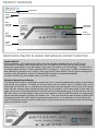
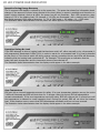
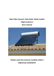
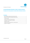
Energy Recovery System E.R.S Mini Edition User Guide Thank you for supporting us by purchasing a PowerFlow Energy Recovery System. You now own the fastest reacting, most advanced, export energy controller on the market today. The PowerFlow E.R.S is a fully automated intelligent device that manages the recovery of exported energy from a solar or wind renewable generation system. No user input is required for ERS operation other than the manual override should you wish to boost your heating device. The main purpose of this guide is to explain how the user interface operates. Please pay particular attention to the Legionella advice on the back page. For your peace of mind, PowerFlow E.R.S and F-POINT technology ® have been independently tested in association with the University of Gloucestershire to ensure regulatory compliance. Please read this user manual carefully before commencing operation. Further information can be found at www.powerflowenergy.com. PRODUCT OVERVIEW PF-ERSMINI-0000000 Serial Number Device Identification Plate Mains Power OUT Connector Mains Power IN Connector 20 LED Power Bar Indicator Manual Boost Button Current Clamp Connection SWITCHING ON/OFF & USING THE MANUAL BOOST FUNCTION Switch ON/OFF During installation, a 20A double pole switch with neon should be installed close to the ERS device. This acts as an isolation switch should the user wish to isolate the ERS unit from the mains supply. Ensure the supply MCB is in the ON position, then switch the isolator to the ON position. The blue LED in the boost button will flash 5 times indicating ERS is booting up. During boot up ERS is performing an auto calibration procedure and is ready to use once the LED stops flashing. Ensure that the heating load is switch to the ON position, if export is detected ERS will begin to operate automatically. To switch off ERS, turn the isolation switch to the OFF position. Using the Manual Boost Button The manual boost button is designed to enable the user to provide supplementary power to the heating load should it be required. To enable the manual boost, push the button once, an audible ‘click’ can be heard and the LED will turn on indicating the manual boost has been started. At this point a 90 minute timer will start counting down allowing enough time for the majority of hot water tanks to fully heat the water. At the end of the timed period, the manual boost will automatically stop, the LED will turn off and ERS will revert to normal operation. During the timed operation, with the LED illuminated, the timed period can be manually stopped by pressing the button once. Take note that during manual boost operation ERS will supply the load with 100% power irrespective of export levels. If no generation is occurring this will result in importing energy during the timed period. During manual boost, the power bar will not illuminate, as per the illustration below. 20 LED POWER BAR INDICATOR Operation During Energy Recovery The 20 segment LED display is referred to as the power bar. The power bar shows live information about changes in the amount of power being diverted to the load. When no export is available and therefore no power is being diverted, such as at night, the power bar will not illuminate. Each LED represents a step change of 5% of the heating load. For example, if 10 LEDs are illuminated, with a heating load of 3kW, this would represent 1500 watts of diversion. i.e. 5% of 3000 watts = 150 watts x 10 = 1500 watts. The illustration below demonstrates how the power bar would appear in the above example. Operation During No Load If the ERS attempts to drive a heating load that has been switch off, either manually or by a thermostat, it will progressively illuminated 6 LEDs (30%) in order to search for a connected load. If no load is detected at this point, or if the load is switch off during energy recovery operation the two end LEDs will illuminate, indicating that the heating load is switched off. For example: This would give an indication that the water has reach temperature and the immersion element has switched off. The illustration below demonstrates how the display would appear in the above example. Over Temperature ERS mini has an internal temperature sensor for safety. If an over temperature situation occurs, the centre 3 LEDs will illuminate and ERS will shut down for 2 minutes. After this period, ERS will attempted to re-start automatically. If the over temperature event still exists, ERS will continue this 2 minute loop until the temperature is reduced to a safe operating level. During this period, ERS will not drive the heating load. If this situation occurs, ensure that ERS has adequate ventilation and has not been covered. The illustration below demonstrates how the display would appear in the above example. TROUBLESHOOTING & FAQs Question Answer ERS does not appear to be heating the water The immersion switch next to the hot water tank must be left in the ON position. Power will only be sent to the immersion heater when export energy is available. Ensure there is enough export energy. ERS will not start operation until 200 watts of export is available. Ensure the water is not already hot. i.e. heated by another source. Re-time the boiler to heat water in the evening rather than the morning. This will give ERS opportunity during the day to heat or pre heat the water. This will ensure maximum savings are achieved. ERS appears to be running the heating load even when there is no export. Check that the current clamp has not been installed back to front. The label on the clamp must be facing the electricity meter, i.e. the incoming grid supply. ERS does not switch ON? Ensure both the MCB (trip switch) supplying the ERS and the 20A double pole isolator is in the ON position. How does the manual boost function work? Pressing BOOST ON will override ERS at any time and switch the heating device on to full. A countdown timer of 90 minutes will start . After the timed period has completed, ERS will revert to normal operation. Where can I find more information if my question is not listed here? Please visit www.powerflowenergy.com for more service information ! Check that the current clamp has not been installed in the wrong location. IMPORTANT SAFETY INFORMATION Caution: Please take note of the following: 1. 2. 3. Risk of burns due to hot enclosure. During operation the ERS enclosure may become hot to touch. Always use caution when touching the enclosure after long periods of operation. DO NOT place objects over the enclosure. PowerFlow ERS uses the metal enclosure to dissipate heat. Covering the enclosure may cause product failure. Please ensure adequate ventilation is provided. For further information refer to the installation guide. DO NOT disassemble the ERS unit at any time. PowerFlow ERS contains live parts inside, never disassemble the system. Important: Legionella Advice: ERS Mini should NOT be installed in all electric houses without a secondary water heat source. (Please speak to your installer for further information) Legionella is a bacteria that can grow in water below 60ºC. It is common practice for hot water and heating systems to raise the water temperature on a weekly basis over 60ºC in order to kill any bacteria growth. Due to the very nature of ERS it is possible during periods of low energy export to partially heat the water. In systems without a second heating source such as a boiler to ‘top up’ the water temperature, it is possible that unused warm water could remain in a temperature range where bacteria can grow. Because the particulars of each installation are different, PowerFlow Energy cannot take responsibility for controlling the risk of legionella. It is the installer’s responsibility to ensure that this risk is controlled. Adequate water exchange and/or additional heating must be supplied in order to raise the water temperature above 60ºC on a minimum of a weekly basis. This can NOT be achieved using ERS mini as it does not contain a timer feature. In this instance ERS 4 is required. Further advice on Legionella can be found at www.hse.gov.uk/legionnaires If you have technical problems, please contact your installer in the first instance. The following information will be required in order to provide you with the necessary assistance. ERS Model Number ERS Serial Number Type and number of heating elements connected Location of ERS unit within the building PowerFlow Energy Ltd , Barrs Court, Netherwood Road Rotherwas Industrial Estate, Herefordshire HR2 6JU, United Kingdom For Support, please email us: Email: [email protected] www.powerflowenergy.com. EN PF-ERSmini-USER-V1.2