1
for
External Ignition Lead Relay
3890 Series Siren Systems
DESCRIPTION:
Normal installation procedure requires the siren’s +12VDC power connection to be connected to the vehicle’s
ignition circuit so that the ignition key must be in the on position for the system to operate. In cases where
vehicle security is a consideration it may be desirable to connect the siren system directly to the vehicle’s
battery in order to allow the siren and lighting control to be operated with the vehicle’s ignition switch in the off
position. This requires that the siren’s +12VDC power connection be routed through the normally closed (NC)
contacts of a SPDT relay (user supplied). This is easily accomplished using the wiring method described below.
OPERATION:
Refer to the appropriate user instruction manual for details on the configuration and operation of the
MasterCOM Siren System.
WIRING:
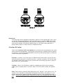
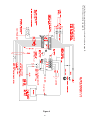
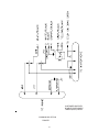
The basic connections are shown in Fig. 1 below. Please note that other equivalent relays and vehicles of
different makes and models may require slightly different connections. Mount and wire the siren amplifier in
compliance with the instructions in the user manual. Read and comply with all safety warnings. Refer to the
vehicle manufacturer’s wiring diagram to determine the location and wire color of the start circuit. Securely
mount the external relay. Use the appropriate wire size as indicated in Fig. 1, and insure that all wiring is
properly terminated and secured in a manner that does not interfere with other systems within the vehicle.
+12VDC FROM BATTERY
PSE P/N 680
BOSCH 0 332-204-150
OR EQUIVALENT
20A FUSE
(USER SUPPLIED)
NC (87a)
TO SIREN +12VDC
QUICKSLIDE CONNECTOR
C (30)
N0 (87)
WIRE SIZE - 12 AWG
WIRE SIZE - 12 AWG
(85)
TO VEHICLE START CIRCUIT
R/LB WIRE
ON FORD CROWN VIC
WIRE SIZE - 18 AWG
(86)
GROUND
External relay wiring to allow electronic siren
and lighting control to operate directly from
vehicle battery (vehicle ignition OFF) and
provide ignition reset to siren during vehicle restart.
Fig. 6
21