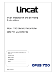
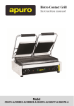
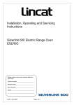
1
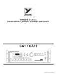
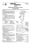
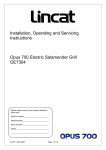
` User, Installation and Servicing Instructions Opus 700 Electric Solid Top Range OE7015 IS445 ECN3694 Dear Customer, Thank you for purchasing this Lincat product. This is just one of over 450 different items of catering equipment available which is constantly being extended and improved. Details are available from your local distributor or direct from us. Used for the purposes for which it is intended, and with careful maintenance as outlined in this User Guide, your Lincat product will give you years of trouble free service. For use in GB & IE IMPORTANT INFORMATION Please read all of the safety and operating instructions carefully before using this product. Please pay particular attention to all sections of this User Guide that carry warning symbols and notices. WARNING! This is a Warning symbol. This symbol is used throughout the user guide whenever there is a risk of personal injury. Ensure that these warnings are read and understood at all times. CAUTION! This is a Caution symbol. This symbol is used throughout the user guide whenever there is a risk damaging your Lincat product. Ensure that these warnings are read and understood at all times. NOTE: This is a Note symbol. This symbol is used throughout the user guide to provide additional information, hints and tips. IS445 ECN3694 2 CONTENTS Contents Page Customer Information………………………………………………………. Warnings and Precautions………………………………………………… Technical Data……………………………………………………………….. Commissioning………………………………………………………………. Check List of Enclosures…………………………………………………... Installation…………………………………………………….……………… User…………………………………………………………………………….. Component Replacement ………………………………………….……… Spare Parts List……………………………………………………………… Wiring Diagrams………………………………………………………………. Service information………………………………………………………….. Guarantee………………………………………………………….………….. IS445 ECN3694 3 2 4 5 6 6 7 8-9 10 - 12 12 13 14 14 WARNINGS AND PRECAUTIONS It is mandatory that all appliances are installed, commissioned and serviced by a qualified and competent person as defined by the regulations in force in the country of installation. Failure to comply will invalidate the warranty. WARNING! This appliance must be installed by a competent installation engineer in accordance with the installation instructions, and should conform to the following requirements: Local and National Building Regulations Fire Precautions Act Health & Safety At Work etc Act BS EN 60335-1 Safety of Household and Similar Electrical Appliances BS EN 60335-2-36 Particular Requirements for Commercial Electric Cooking Ranges, Ovens, Hobs and Hob Elements BS EN 60335-2-42 Particular Requirements for Commercial Electric Forced Convection Ovens, Steam Cookers and Steam-Convection Ovens Do not obstruct or block the appliance flue. After operation, some parts of the appliance will remain hot for a period of time. Please take care to avoid accidental burns. CAUTION! All equipment must be earthed to prevent shock. A means of disconnection must be incorporated in the fixed wiring having a contact separation of at least 3.0mm in all poles. Supply cords shall be oil-resistant, sheathed flexible cable not lighter than ordinary polychloroprene or equivalent synthetic elastomer-sheathed cord (code designation 30245 IEC 57) Connection of the electrical supply cable is made at the rear of the unit. Remove the protective cover and fit a suitable cable into the strain relief and then to the inlet terminal block. The unit is supplied for connection to a three-phase supply. Connections are provided to allow termination of all three-phase cables, although only two are used to power the unit. If the unit is to be fed from a single-phase then the two supply terminals will need to be connected together using a wire link. IS445 ECN3694 4 TECHNICAL DATA OE7015 Model Dimensions Overall Height (mm) Width (mm) Depth (mm) Weight (kg) Hob Cooking Surface w x d (mm) Usable Oven Capacity w x d x h (mm) Oven Shelf Size (mm) w x d 950 900 815 190 900 x 600 715 x 540 x 400 770 x 530 Electrical Fan Assisted Oven Rating Hob Rating – per solid plate Total Power Rating @ 400V three phase Oven Fan Rating Hob Fan Rating Voltage 3N~ Amps 3N~ Total Power Rating IS445 ECN3694 5 6.0 kW 4.7 kW Phase 1 6.7 kW Phase 2 4.0 kW Phase 3 4.7 kW 2 x 32 W 2 x 18W Phase 1 29.1A Phase 2 17.4A Phase 3 20.4A 15.4 kW COMMISSIONING PREPARATION Remove all packaging and protective coatings prior to installation. The appliance is supplied as standard with swivel castors. Adjustable feet are available, if required, for these appliances. OE7015 CHECK LIST OF ENCLOSURES Please ensure the following items are included with this piece of equipment: Model Wire Shelf Warranty Card User Instructions OE7015 3 1 1 Tick SERIAL NUMBER NOTE Each appliance manufactured at Lincat has a unique identifying number found in the top right hand corner of the data plate attached at the rear of the appliance. Please record that number in the space provided should it be required for future reference. Serial Number MARK OF CONFIDENCE Every single product that leaves our factory bears a serial plate showing the assembler’s initials. It’s a mark of confidence we have in our people and our manufacturing process. IS445 ECN3694 6 INSTALLATION SITING The appliance must be installed in accordance with the appropriate regulations listed prior. The appliance should be installed on a level surface ensuring the unit is stable, firmly located and positioned to minimise the possibility of accidental touching. A clear space of at least 100mm must be left to the rear of the appliance to allow for servicing with a clear space of 600mm to the front to allow for safe operation. A minimum space of 100mm must be left between any side of the unit and any combustible surface or walls. Any partitions, walls or kitchen furniture in close proximity must be of non-combustible materials and not be closer than 100mm from the sides and rear of the flue. ELECTRICAL SUPPLY AND CONNECTION Connection of the electrical supply cable is made at the rear of the unit. Remove the protective cover and fit a suitable cable into the strain relief and then to the inlet terminal block. The unit is supplied for connection to a three-phase supply. Refer to schematics on page 13. LOCKING OF WHEELS When the appliance has been installed in its intended position the front castors should be locked by depressing the locking tabs on the castors. Locks should only be released for the intention of moving the appliance for cleaning purposes and or routine servicing of the appliance. IS445 ECN3694 7 USER INSTRUCTION APPLIANCE USE This appliance is only for professional use and should only be used by qualified personnel. Ensure that the person responsible understands how to safely operate, clean and shut down the appliance and MAINSaware POWER ON of the position and operation of the isolating switchPAN is made inSUPPORTS the event of an emergency. ON / OFF INDICATOR OVEN ELEMENT POWER ON HOB INDICATOR CONTROL PANEL HOB FRONT MAINS POWER ON LH HOB CONTROL RH HOB CONTROL CONTROL PANEL OVEN THERMOSTAT CONTROL KNOB LH FRONT HOB LH REAR HOB MIDDLE FRONT HOB MIDDLE REAR HOB RH FRONT HOB RH REAR HOB HOB CONTROL KNOBS OVEN THERMOSTAT CONTROL OVEN ELEMENT POWER ON LH HOB ELEMENT POWER ON RH HOB ELEMENT POWER ON HOB INDICATORS 1 2 3 4 5 6 OFF HIGH LOW HOTPLATE CARE Before using the appliance for the first time, clean the protetive coating from the Solid Top1 OF surface 1 with a mild detergent. Turn on the Hotplate to maximum and spread approximately 2kg of household salt evenly over the surface. Run the unit for around 20mins until salt discolours. Turn off the unit, allow to cool and remove and discard the salt. The unit is now ready for use. Note: The minimum temperature of the hottest point of the solid top (around the centre of the plate) is approximately 3900C. HOTPLATE OPERATION Hotplates are controlled by energy regulators, 6 is the hottest. ‘Off’ is indicated by a filled circle, as shown in the control panel illustrations above. NB: It is important that good quality pans are used to ensure maximum efficiency. Wherever possible always use lids. OVEN SETTING Check the green ‘power on’ neon on the control panel is illuminated. Set the control knob to the desired temperature in degrees Celsius. The orange light will illuminate indicating that power is being supplied to the elements. The orange light will go out when the oven has achieved the set temperature. Periodically the orange light will illuminate to indicate that the oven temperature has fallen and the elements are turned on to top up the temperature. OPENING OF THE O VEN DOOR Care must be taken to avoid injury when opening the oven door when the oven is in use as hot air will rapidly escape. IS445 ECN3694 8 SHUT DOWN To shut down the appliance rotate all control knobs clockwise to the OFF position. After operation, some parts of the appliance will remain hot for a period of time; care should be taken to avoid the risk of burns. CLEANING Ensure the Electricity supply is isolated before commencing cleaning. All removable parts can be cleaned in a commercial dishwasher. Hotplates Ensure hotplates are cool before cleaning. Hotplates can be wiped down with a moist cloth. For more stubborn dirt commercial cleaners and scourers may be used. Oven The unit features removable liners for the sides, base and top of the oven to allow easy cleaning away from the unit. After allowing the unit to cool, slide out the top liner from the oven. Slide out the base tray. Remove the shelves from the oven, See below. To remove the shelf supports, lift up and out to disengage. Lift off each of the side liners from the unit. External surfaces can be cleaned using a cloth moistened with a warm detergent solution. For heavy, stubborn deposits a de-greasing agent ‘CARBON-OFF’ is available from Lincat upon request. When replacing parts that have been removed for cleaning, ensure correct relocation so as not to affect oven performance. Tilt shelf up at rear and pull to disengage External Cleaning Do not use abrasives on stainless steel or enamelled parts. Do not use any products containing chlorine or hydrochloric acid to clean stainless steel surfaces. Do not clean the appliance using a water jet. IS445 ECN3694 9 COMPONENT REPLACEMENT Energy Regulator & Hotplate Switch 1. Remove the control knobs and fascia panel, by firstly removing fixing screws . 2. Protect the surrounding area panel work with soft material and support the fascia panel against it. Access to the energy regulator is now possible. Remove completely the component screws from the fascia. 3. Remove and replace wires correctly, ideally transferring wires across, from the old switch to the new, one at a time. Numbering each wire with an indelible pen may also help. 4. Replacement is a reversal of the removal sequence. Be careful not to trap the wiring harness whilst replacing the fascia and check the wiring is still protected where it passes through the heat deflector. FAN CASING FASCIA REAR COVER FASCIA FIXING SCREWS Thermostat 1. Follow the procedure as for replacing Hotplate Switches above. 2. Unscrew the heat deflector. 3. Unclip the thermostat phial and remove the thermostat completely, keep the insulating sleeve to use on the new thermostat. 4. When replacing the new thermostat ensure that the insulation is secured in place and that the routing is secure to prevent shorting internally with any switch gear. 5. Replacement is a reversal of the removal sequence. Be careful not to trap the wiring harness whilst replacing fascia. IS445 ECN3694 10 Hotplate & Hotplate Elements 1. Lift and flip over the Hotplate, taking care not to snag the supply cord. 2. Remove the Element Lid and disconnect wires, noting their position. 3. Unscrew the Element Cover fixing screws x4 and lift away the Cover. 4. The Elements are now exposed. 5. Replacement is a reversal of the removal procedure, taking care not to trap the wiring harness. 6. Check the unit for electrical safety. ELEMENT LID FIXING SCREWS x4 ELEMENT COVER FIXING SCREWS ELEMENT LID ELEMENT LID CENTRE ELEMENT CALIBRATION SCREW ACCESS HOLE Oven Fans 1. Ensure that the electrical supply is disconnected. 2. Remove the oven shelves. 3. Loosen the fan guard screws and lift off the keyhole slots. 4. Remove the hex. head nut from the centre of the fan, this is a left-hand thread, and remove the fan blade. 5. Working from the back of the unit, remove the rear cover panel. 6. Remove the electrical connections from the relevant motor. 1 OF 1 7. Remove the three securing screws and extract the motor unit. 8. Replacement is the reversal of removal. 9. Check the unit for electrical safety. Hob Fans 1. Ensure that the electrical supply is disconnected. 2. Working from the rear of the appliance, remove the Rear Cover. 3. Undo the fixing screws and remove the Fan Casing complete with the Fan, taking care not to trap the supply wires. 4. Unscrew the Fan from the Fan Casing and remove the Fan Guard. 5. Replacement is a reversal of the removal procedure, taking care not to trap the wiring harness. Note:: The fan blows air into the appliance. Contactor 1. Ensure that the electrical supply is disconnected. 2. Working from the back of the unit, remove the rear cover. 3. Remove the electrical connections from the contactor. 4. Release the clip from the base of the contactor. 5. Replacement is the reversal of removal. 6. Check the unit for electrical safety. IS445 ECN3694 11 Over Temperature Cut-Out Thermostat & Control Thermostat 1. Ensure that the electrical supply is disconnected. 2. Remove the thermostat bulb from the top of the oven. 3. Working from the back of the unit, remove the rear cover panel. 4. Remove the electrical connections from the thermostat housing. 5. Remove the fascia panel. 6. Pull the thermostat bulb through the oven back. 7. Remove the two securing screws and remove the thermostat unit. 8. Replacement is the reversal of removal. 9. Check the unit for electrical safety. SPARE PARTS LIST Part Number BU72 CA143 CA145 CO215 DO211 EL03 EL278 EL248 EN10 FA12 FA102 GL77 HA77 KN228 KN233 LE37 NE39 NE40 SE25 SH81 SP56 SR07 S/R0181 SW58 TH46 TH111 IS445 ECN3694 Part Description Door Bushes 125mm Braked Swivel Castors 125mm Un-Braked Swivel Castors Contactor Door Catch Assembly Hotplate Element (Circular) Hotplate Element (Outer) Element – 3kW Energy Regulator LH Fan/Motor Assembly RH Fan/Motor Assembly Cable Restraint Door Handle Control Knob – Oven Control Knob – Hob Adjustable Leg - 150mm Green Neon Amber Neon Door Seal Oven Shelf Leg Spanner Side Rack Axial Fan Fan Switch Thermostat Safety Cut-Out Thermostat 12 OE7015 Oven Wiring (E329) Connect to inner bulkhead via heat deflector screw NE39 GREEN NEON 22 15 17 B 23 B 12 SW58 FAN SWITCH 11 10 29 27 26 Connect to fascia 32 28 NE40 AMBER NEON EL248 ELEMENT EL248 ELEMENT 19 TH46 OVEN THERMOSTAT 31 16 30 9 8 24 7 25 FA12 FAN FA12 FAN TH63 SAFETY THERMOSTAT 18 6 5 4 21 20 L1 L2 L3 N TE47 TERMINAL BLOCK CO214 CONTACTOR TE55 EARTH TAG 13 1 14 2 3 32 OE7015 Hob Wiring (E426) 29 30 1 2 3 4 5 6 7 8 9 10 11 12 13 14 15 16 17 18 19 20 21 22 23 24 25 26 27 28 CA09 CA09 CA09 CA09 CA09 CA09 CA09 CA09 CA09 CA09 CA09 CA09 CA36 CA36 CA36 CA36 CA36 CA36 CA36 CA35 CA35 CA35 CA35 CA10 CA10 CA35 CA35 CA35 400 400 400 150 150 150 400 400 400 550 550 550 1850 1850 1850 700 1400 1850 1300 400 1750 150 150 600 600 120 120 120 120 1750 P- # P- # P- # P- # P-# P- # P- P P- P P- P P-P P-P P-P P- # P- # P- P P-P P-P P-# P-P P-# P-# P-P P-P P-P P-P P-P P-P P-P P-P P-P 06.09 CA13 300 P-SR 3324 OE7008 - A007 OD7007 - A007 OVEN WIRING CA35 CA35 E371 EL03 TRIPLE RING ELEMENT EL03 TRIPLE RING ELEMENT EL278 ELEMENT 36 EL278 ELEMENT 37 CONNECT TO EARTH POST ON SUMP TRAY CONNECT TO EARTH POST ON SUMP TRAY 19 8 24 20 28 29 21 33 15 16 27 18 30 41 7 40 43 S/R0181 FAN TE47 TERMNAL BLOCK S/R0181 FAN 17 42 22 4 3 26 SW58 SWITCH 31 13 B B 5 6 25 23 12 14 NE40 AMBER NEON EN10 ENERGY REGULATOR SW58 SWITCH 11 EN10 ENERGY REGULATOR 1 2 NE40 AMBER NEON 32 34 9 10 CONNECT TO EARTH POST ON SUMP TRAY SEE DRAWING E371 FOR OVEN WIRING (SHOWN DOTTED) 35 CONNECT TO FASCIA 44 TE47 TERMNAL BLOCK L1 L2 L3 TE55 EARTH TAB N USE IN CONJUNCTION WITH E371 IS445 ECN3694 13 1 OF 1 SERVICE INFORMATION Catering equipment should be routinely serviced to ensure a long trouble free life. It is recommended that this appliance is serviced every 6 months by a competent engineer. For help regarding the installation, maintenance and use of your LINCAT equipment, please call:- LINCAT SERVICE HELP DESK +44 (0) 1522 875520 AUTHORISED SERVICE AGENTS All service work, other than routine cleaning, to be carried out by our authorised agent. We cannot accept responsibility for work carried out by other persons. Please quote both the model and serial numbers from the data plate attached to the unit. Give brief details of the service requirement. If possible please quote the product code of the part number you require. Work carried out under warranty will normally be undertaken only during normal working hours, i.e. Monday to Friday, 8.30 a.m. - 5.00 p.m. CONDITIONS OF GUARANTEE The guarantee does not cover:1) 2) 3) Accidental breakage or damage Operational misuse, wear and tear from normal usage, incorrect adjustment, or neglect. Incorrect installation, maintenance, modification or unauthorised service work. IS445 ECN3694 14