1
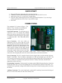
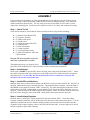
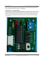
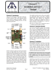
Cheap Control Systems Cheap Six Channel (C6C) Servo Controller v2.0 QUICK START 1. 2. 3. 4. Plug your PS2 game pad into the C6C game pad connector Connect your servos, motor controllers, etc. to the C6C just like an R/C receiver Apply power to the C6C via the Power Terminal Block If you are using a tethered game pad, the Analog light should illuminate. If you are using a cordless game pad, the receiver may or may not have a light. 5. Have fun!! CONNECTIONS The completed C6C is shown in Figure 1. The PCB is 1.75 by 2.0 inches, not including the PS2 game pad connector (not shown). Game Pad Connection: The PS2 game pad is connected to the C6C through the standard game pad connecter and cable provided, which is connected to the PCB using the 6-pin header via solder holes BLU, YEL, GRA, BRO, RED, and BLK. Servo Connection: R/C servo cables are connected to the C6C on the right side of the PCB using the horizontal pin headers labeled S1 through S6. For all servos, the red power wires should be connected to the R (Red) pins in the center vertical column and the black ground wires should be connected to the B (Black) pins in the right vertical column (closest to the edge of the board). The servo signal wire (Futaba = White, Hitec = Yellow, Airtronics = Blue) should be connected to the S (Signal) pins in the left vertical column (closest to the microcontroller). Power Connection: The C6C is supplied electrical power using the blue, two-hole terminal with ports labeled V+ and GND . The C6C requires a minimum of +6 VDC and can handle up to +8.4 VDC. The C6C provides power directly to the servos and to either the tethered game pad or wireless game pad receiver, whichever is connected to the game pad connector. Battery connections should include appropriate switches and fuses. Programming Connection: The horizontal 5 pin header marked PROG (Program Interface) located on the top edge of the C6C is reserved for updating the C6C microcontroller's software in the future. It is currently used to optionally configure dual-channel mixing for the left and/or right joysticks (see below for details). Auxiliary Connection: The vertical 4 pin header marked AUX (Auxiliary) located on the left edge of the C6C is reserved for future use and is not currently used. Revision 2008-04-13 Copyright 2008, Cheap Control Systems 2 of 15