1
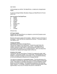
www.zeeltronic.com
[email protected]
updated 18.10.2008
program version: 000.031008
USER MANUAL
PCDI-M1V
PROGRAMMABLE CDI IGNITION AND PV CONTROLLER
Ignition controller is specially designed for Cagiva Mito and Mito ev originally equipped with
standard Kokusan ignition. PCDI-M1V replaces exhaust valve controller and standard
Kokusan ignition.
Very important!
Resistor spark plugs must be used, because they produce less electromagnetic disturbances.
TECHNICAL DATA
Limit values:
- minimum revs
- maximum revs
- minimum supply voltage
- maximum supply voltage
- max. supply voltage for 1 minute
- current draw
- maximum continuous current for shift light output
- peak current for shift light output
200 RPM
20000 RPM
8 Volts
16 Volts
35 Volts
25 mAmp
1 Amp
5 Amp
Circuit is protected against reverse supply voltage (wrong connection).
Features:
- CDI charged from hi voltage charging coils (generator)
- running from stator without pickups
- store and load function for 2 ignition maps
- external switch for changing ignition map while riding
- shift light output
- quick shift (shift kill)
- tachometer output
- advance/retard whole ignition curve
- three stage rev limit (retard timing, reduced spark, spark off)
- timing compensation curve
- timing calculation for every 1 RPM change (1000, 1002, .. , 9805, 9806, ...)
- programmable power valve actuation
- store and load function for 5 PV curves
- programmable PV deviation
-1-
- programmable max close and max open positions
- self PV test on power-up
- PV error detecting (position sensor failure, servo motor failure)
- easy and fast programming on the field, via hand held programmer
- programming while machine running - you can immediately see effects
- monitoring of rev's, ignition and PV angle, via LCD(hand held programmer)
- fast processing for high accuracy - delays from 1us
1.
HOW TO ENTER MENU
PCDI must be connected to power supply. Connect programmer to PCDI and wait few
seconds for activation of programmer and then press enter. With pressing + or - you can
move through menu and select with pressing enter .
Exit menu with selecting Exit.
2.
MENU ORGANISATION
Set Ign.
Set PV
Exit
2.1.
SET IGNITION PARAMETERS SUBMENU
Load Ign. Curve
Save Ign. Curve
Ignition Curve
Advance
Shift Light
Shift Kill Time
Rev Limit
Static Angle
Remote SW
Compensation Curve
Exit
2.2.
- set ignition parameters submenu
- set PV parameters submenu
- load previously saved ignition curve set (from #1 to #2)
- save new ignition curve set (from #1 to #2)
- ignition curve parameters submenu
- advance/retard whole ignition curve
- shift light
- shift kill time
- rev limit
- static angle (stator position)
- activating/deactivating external switch
- timing compensation curve
SET PV PARAMETERS SUBMENU
Load PV Curve
Save PV Curve
Set PV Curve
Deviation +Close Position
Open Position
PV test
Exit
- load previously saved curve (from #1 to #5)
- save new curve (from #1 to #5)
- valve curve parameters submenu
- deviation of valve position
- max close valve position
- max open valve position
- valve position test
-2-
3.
LOAD IGN. CURVE
Enter menu and move to Load Ign. Curve with pressing + or - and then press enter .
Now you can select position number of previously saved ignition curve set, with pressing +
or - and then press enter .
4.
SAVE IGN. CURVE
Enter menu and move to Save Ign. Curve with pressing + or - and then press enter .
Now you can select position number to which you want to save your ignition curve set, with
pressing + or - and then press enter .
5.
Change IGNITION CURVE
Enter menu and move to Ignition Curve with pressing + or - and then press enter .
Now you are in submenu for setting ignition curve.
Submenu organisation:
Nr. of Points
- number of ignition curve points (from 4 to 10)
1)
- first ignition curve point
2)
- second ignition curve point
...
...
...
...
Exit Curve
- exit submenu
Important!
To avoid wrong processing, don't make unreasonable curve course.
Every time you make any changes to ignition curve, it is automatically saved to #0 position.
Then you can save it to any other position number from #1 to #2.
Curve Example with six curve points:
-3-
5.1.
Change NUMBER OF IGNITION CURVE POINTS
Move to Nr. of Points with pressing + or - and then press enter .
Now you can select number of ignition points, with pressing + or - and then press enter .
5.2.
Change PARAMETERS OF IGNITION CURVE POINT
Move to point you want to change, with pressing + or - and then press enter .
Now you can change rev point with pressing + or - (in 100 rpm steps) and then press
enter .
Now you can change advance angle with pressing + or - (in 0.1deg steps) and then press
enter .
6.
Set ADVANCE
With this setting is possible to advance or retard whole ignition curve. When setting is
positive then ignition curve is advanced and when setting is negative than ignition curve is
retarded. With Advance 0.0deg, ignition curve is unchanged.
Enter menu and move to Advance with pressing + or - and then press enter .
Now you can set advance with pressing + or - (in 0.1deg steps) and then press enter .
7.
Set SHIFT LIGHT
Enter menu and move to Shift Light with pressing + or - and then press enter .
Now you can change rev point with pressing + or - (in 100 rpm steps) and then press
enter .
8.
Set SHIFT KILL TIME
Enter menu and move to Shift Kill Time with pressing + or - and then press enter .
Now you can change kill time with pressing + or - (in 10 ms steps) and then press enter .
9.
Set REV LIMIT
Enter menu and move to Rev Limit with pressing + or - and then press enter .
Now you can change rev limit with pressing + or - (in 100 rpm steps) and then press
enter .
-4-
10.
Set STATIC ANGLE
Static angle of stator must be set to 1,60mm BTDC. For more information about setting
procedure, look at Cagiva "Mito Workshop Manual" on page M18.
Default static angle for PCDI-M1V in degrees for 1,60mm BTDC is 20deg.
Enter menu and move to Static Angle with pressing + or - and then press enter .
Now you can set static angle with pressing + or - (in 0.1deg steps) and then press enter .
11.
Set REMOTE SW
Enabling or disabling external switch for changing ignition curves while riding.
Enter menu and move to Remote SW with pressing + or - and then press enter .
Now you can enable or disable external switch with pressing + or - and then press enter .
12.
Set COMPENSATION CURVE
Stator has only charging coils and no pickup. Trigger timing is not constant, because signal is
taken from charging coils. Compensation curve is needed to correct possible timing error.
Important!
Do not make any changes, if you are not sure about procedure. Unit is already compensated
and normally does not need corrections.
To check, if timing is correct flat ignition curve must be programmed (for example 15deg).
Make mark at 15deg on the flywheel and check with stroboscope light if timing is correct
through all rev range.
Enter menu and move to Compensation Curve with pressing + or - and then press enter .
Programmer will show information Read instructions!!! and then press + .
Submenu organisation:
1) 1000 RPM; 0,0 deg
2) 2500 RPM; 0,0 deg
3) 4000 RPM; 0,0 deg
4) 5500 RPM; 0,0 deg
5) 7000 RPM; 0,0 deg
6) 8500 RPM; 0,0 deg
7) 10000 RPM; 0,0 deg
8) 11500 RPM; 0,0 deg
9) 13000 RPM; 0,0 deg
Exit
- exit submenu
Move through submenu with pressing + or - to the point you want to change and press
enter . Set compensation angle with pressing + or - and press enter to confirm.
-5-
13.
LOAD PV CURVE
Enter menu and move to Load PV Curve with pressing + or - and then press enter .
Now you can select position number of previously saved ignition curve set, with pressing +
or - and then press enter .
14.
SAVE PV CURVE
Enter menu and move to Save PV Curve with pressing + or - and then press enter .
Now you can select position number to which you want to save your ignition curve set, with
pressing + or - and then press enter .
15.
Set PV Curve
Enter menu and move to Set PV Curve with pressing + or - and then press enter .
Now you are in submenu for setting valve curve.
Submenu organisation:
Nr. of Points
- number of valve curve points (from 2 to 8)
1)
- first valve position point
2)
- second valve position point
...
...
...
...
Exit
- exit submenu
Important!
To avoid wrong processing, don't make unreasonable curve course.
Every time you make any changes to valve curve, it is automatically saved to #0 position.
Then you can save it to any other position number from #1 to #5.
15.1. Change Number of Curve Points
Move to Nr. of Points with pressing + or - and then press enter .
Now you can select number of curve points, with pressing + or - and then press enter .
15.2. Change Parameters of Valve Position Curve Points
Move to point you want to change, with pressing + or - and then press enter .
Now you can change rev point with pressing + or - (in 100 rpm steps) and then press
enter .
Now you can change valve position from 0% to 100%, with pressing + or - (in 1% steps)
and then press enter .
-6-
16.
Deviation
Enter menu and move to Deviation with pressing + or - and then press enter .
Now you can change deviation from 2% to 20% with pressing + or - (in 1% steps) and then
press enter .
Deviation means how accurate valve is moved to calculated position. If deviation is too low
then servo motor won't be stabile – it will always search for calculated position in small
movements. Default setting is +-5% and should meet in most cases.
17.
Max Close Position
Enter menu and move to Close Position with pressing + or - and then press enter .
Now you can set close position with pressing + or - and then press enter .
Max close position is when curve is set to 0%. This close position can be moved to any
desired position.
Default max close position is 430.
18.
Max Open Position
Enter menu and move to Open Position with pressing + or - and then press enter .
Now you can set open position with pressing + or - and then press enter .
Max open position is when curve is set to 100%. This open position can be moved to any
desired position.
Default max open position is 560.
19.
PV Test
Enter menu and move to PV Test with pressing + or - and then press enter .
Now you can set valve position with pressing + or - and then press enter .
PV test can be used for testing or measuring valve position. Valve can be moved to any
position from 0% to 100%, without engine running.
20.
MONITORING
Connect programmer to PCDI and wait few seconds for activation of programmer. Fist
information displayed on the programmer is software version.
With programmer you can watch revs, calculated advance ignition angle and PV valve
position.
Information!
You can connect or disconnect PCDI unit from programmer any time you want, without any
harm. It is not important, if motor running or not and if power supply is connected or not.
Important!
Do not use too much force when connecting or disconnecting programmer unit!
-7-
21.
ERROR REPORTS
Two errors can be displayed:
Program Memory Error - when program memory is corrupted. With this error present,
function of program could be faulty.
EEPROM Error - when eeprom memory is corrupted. All programmable data are stored in
eeprom memory (curve, rev limit...). With this error present, function of program could be
faulty. You must check all your settings and correct changed.
PVerror 1 – position sensor error, or servo motor disconnected
PVerror 2 – servo motor error (short connection)
-8-