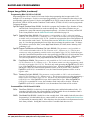
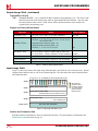
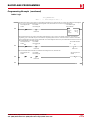
1
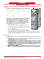
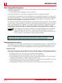
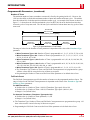
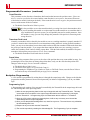
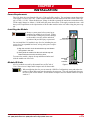
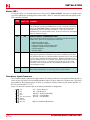
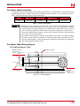
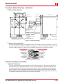
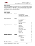
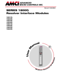
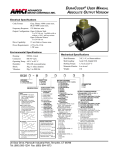
ADVANCED
MICRO CONTROL S INC.
Manual #: 940-05041
od
ule
s
al
u
an
M
User
M
1561
Multi-Turn
Resolver Interface Modules
A
ll e
n-
Bra
50
C
dle y S L
0
I/
O
GENERAL INFORMATION
Important User Information
The products and application data described in this manual are useful in a wide variety of different applications. Therefore, the user and others responsible for applying these products described herein are responsible
for determining the acceptability for each application. While efforts have been made to provide accurate
information within this manual, AMCI assumes no responsibility for the application or the completeness of
the information contained herein.
UNDER NO CIRCUMSTANCES WILL ADVANCED MICRO CONTROLS, INC. BE RESPONSIBLE OR
LIABLE FOR ANY DAMAGES OR LOSSES, INCLUDING INDIRECT OR CONSEQUENTIAL DAMAGES OR LOSSES, ARISING FROM THE USE OF ANY INFORMATION CONTAINED WITHIN THIS
MANUAL, OR THE USE OF ANY PRODUCTS OR SERVICES REFERENCED HEREIN.
Throughout this manual the following two notices are used to highlight important points.
WARNINGS tell you when people may be hurt or equipment may be damaged if the
procedure is not followed properly.
CAUTIONS tell you when equipment may be damaged if the procedure is not followed
properly.
No patent liability is assumed by AMCI, with respect to use of information, circuits, equipment, or software
described in this manual.
The information contained within this manual is subject to change without notice.
Standard Warranty
ADVANCED MICRO CONTROLS, INC. warrants that all equipment manufactured by it will be free from
defects, under normal use, in materials and workmanship for a period of [1] year. Within this warranty
period, AMCI shall, at its option, repair or replace, free of charge, any equipment covered by this warranty
which is returned, shipping charges prepaid, within one year from date of invoice, and which upon examination proves to be defective in material or workmanship and not caused by accident, misuse, neglect, alteration,
improper installation or improper testing.
The provisions of the “STANDARD WARRANTY” are the sole obligations of AMCI and excludes all other
warranties expressed or implied. In no event shall AMCI be liable for incidental or consequential damages or
for delay in performance of this warranty.
Returns Policy
All equipment being returned to AMCI for repair or replacement, regardless of warranty status, must have a
Return Merchandise Authorization number issued by AMCI. Call (860) 585-1254 with the model number
and serial number (if applicable) along with a description of the problem. A “RMA” number will be issued.
Equipment must be shipped to AMCI with transportation charges prepaid. Title and risk of loss or damage
remains with the customer until shipment is received by AMCI.
24 Hour Technical Support Number
24 Hour technical support is available on this product. For technical support, call (860) 583-7271. Your call
will be answered by the factory during regular business hours, Monday through Friday, 8AM - 5PM EST.
During non-business hours an automated system will ask you to enter the telephone number you can be
reached at. Please remember to include your area code. The system will page one of two engineers on call.
Please have your product model number and a description of the problem ready before you call.
ADVANCED MICRO CONTROLS INC.
TABLE OF CONTENTS
General Information
Chapter 2: Installation (continued)
Important User Information ............. Inside Cover
Standard Warranty ........................... Inside Cover
Returns Policy .................................. Inside Cover
24 Hour Technical Support Number Inside Cover
About This Manual
Introduction .............................................. 3
Revision Record ....................................... 3
Revision History ............................ 3
Specifications
Specifications ........................................... 4
Chapter 1: Introduction
Overview .................................................. 5
New Features ........................................... 5
Backwards Compatibility ........................ 6
“-19 option” ................................... 6
Series 1500 Family Members ..................
AMCI Compatible Transducers ...............
Other Compatible Transducers ................
Programmable Parameters .......................
Transducer Type ............................ 8
Number of Turns ........................... 9
Full Scale Count ............................ 9
Count Direction ............................. 10
Transducer Fault Latch .................. 10
Preset Value ................................... 10
6
7
8
8
Backplane Programming .......................... 10
Programming Cycle ....................... 10
Chapter 2: Installation
Power Requirements ................................
Installing the Module ...............................
Module ID Code ......................................
Status LED’s ............................................
11
11
11
12
Transducer Input Connector ..................... 12
Transducer Cable Installation .................. 13
Transducer Cable Wiring Diagram .......... 13
CTT-(x) Wiring Diagram (1561) . 13
Transducer Specifications ........................ 14
Transducer Mounting ............................... 14
Transducer Outline Drawings .................. 14
HTT-20-(x) Outline Drawing ....... 15
Transducer Connector Pinout ....... 15
Autotech Transducer Installation ............. 15
Supported Transducers ................. 15
Autotech Transducer Wiring ........ 16
Chapter 3: Backplane Programming
Data Addressing ....................................... 17
Programming Cycle ................................. 17
Guidelines for Programming an Older Module 17
Multi-Word Format .................................. 18
Output Image Table .................................. 18
Apply Preset Bit: O:X.0/00 ........... 18
Programming Bits:
O:X.0/01 to O:X.0/05 ................. 19
Command Bits:
O:X.0/13 and O:X.0/14 .............. 19
Transmit Bit: O:X.0/15 ................. 20
Ranges and Factory
Default Values ............................ 20
Input Image Table .................................... 20
Position and Tachometer Data ...... 20
Programming Error Bits: I:X.0/00 to I:X.0/08
21
Status Bits: I:X.0/11 to I:X.0/14 ... 21
Acknowledge Bit: I:X.0/15 ........... 21
Programming Example ............................. 22
Ladder Logic ................................. 23
20 Gear Drive, Plymouth Ind. Park, Terryville, CT 06786
Tel: (860) 585-1254 Fax: (860) 584-1973 http:\\www.amci.com
1
TABLE OF CONTENTS
NOTES
2
ADVANCED MICRO CONTROLS INC.
ABOUT THIS MANUAL
It is strongly recommended that you read the following manual. It was first written for the release
of hardware series E, firmware version 6, which introduced many new features into the 1561
module. Backwards compatible “out-of-the-box” with older versions of this module, the new features are easily enabled over the backplane. If there are any unanswered questions after reading
this manual, call the factory. An applications engineer will be available to assist you.
For additional information on our SLC modules as well as the rest of AMCI’s products, check out
our website at www.amci.com.
Firmware rev E, software rev 6+ was released with serial number 59,730. If your 1561 has a
serial number below 59,730, you can still use this manual as long as your are aware of three
items.
1) All new features introduced with hardware series E are not available on your module. See
New Features on page 5 for a list of these features.
2) Older modules do not directly support Autotech RL210 transducers unless they have the
“-19” option.
3) You must not set any of the programming bits associated with the new features when you
program your module. See Guidelines for Programming an Older Module on page 17 for
complete information on programming your module.
Introduction
This manual explains the operation, installation, and programming of 1561 Resolver Interface Module for the
Allen-Bradley SLC 500™ programmable controller systems. Utilizing licensed Allen-Bradley SLC 500 I/O
interface technology, this one slot Resolver Interface Module accepts a single multi-turn transducer input and
plugs directly into the A-B SLC 500 rack. Communicating through I/O registers assigned to the slot, this
module supplies absolute position and tachometer data to any SLC processor from the AMCI resolver based
transducer. Status information is also transferred to the SLC processor.
The AMCI logo is a trademark and “AMCI” is a registered trademark of Advanced Micro Controls Inc.
“SLC” and “SLC 500” are trademarks of Allen-Bradley Company.
This product incorporates technology which is licensed by Allen-Bradley Company, Inc. Allen-Bradley has
not technically approved, nor does it support this product. All warranty and support for this product and its
application is provided solely by Advanced Micro Controls Inc.
Manuals at AMCI are constantly evolving entities. Your questions and comments on this manual and the
information it contains are both welcomed and necessary if this manual is to be improved. Please direct all
comments to: Technical Documentation, AMCI, 20 Gear Drive, Terryville CT 06786, or fax us at (860) 5841973. You can also e-mail your questions and comments to [email protected]
Revision Record
This manual, 940-05041, supersedes 940-05040 and was first released 7/6/2000. Its release corresponds with
the release of hardware series E, firmware version 6. This hardware/firmware change added many features
that are documented in this manual revision.
Revision History
940-05040: 7/21/98. Added parameter range table and updated illustration artwork.
1560-594M: Original cataloged manual
20 Gear Drive, Plymouth Ind. Park, Terryville, CT 06786
Tel: (860) 585-1254 Fax: (860) 584-1973 http:\\www.amci.com
3
SPECIFICATIONS
Module Location
Any SLC 500 I/O slot, including the processor slot of an extended rack. Occupies one
slot.
Position Transducer
Default of AMCI multi-turn brushless resolver
transducer
Can be programmed to use Autotech RL210
128 turn transducers.
Transducer Input Isolation
1500 Vac through isolation transformers
Data Available to Processor
Transducer Position, Velocity and Fault
Diagnostic data
Programmable Parameters
Transducer Type
Number of Turns
Full Scale Count
Preset Value
Count Direction
Transducer Fault Latch
Program Storage
EEPROM Memory
Minimum 100,000 write cycles
Position Update Time
400 microseconds
4
Position Resolution
AMCI 100, 180 turn Transducers:
Programmable to 4,096 counts per turn
AMCI 1,000, 1,800 turn Transducers
Programmable to 409.6 counts per turn
Autotech Transducers:
Programmable to 1,024 counts per turn
Tachometer Resolution and Range
1 RPM over 0 to 3,750 RPM range. Updated
every 32 milliseconds
DC Supply Voltage from Backplane
0.090A max. @ 5Vdc nominal
0.055A max. @ 24Vdc nominal
0.160A max. @ 24Vdc under short circuit
conditions
Environmental Conditions
Operating Temperature: 0 to 60° C
Relative Humidity: 5 to 95%
(w/o condensation)
Storage Temperature: -40 to 85°
Module ID Code
3514
Reserves 8 Input and 8 Output Registers
Number of registers scanned can be set using
SPIOGA Configuration.
Registers Used
4 Input, 7 Output
ADVANCED MICRO CONTROLS INC.
CHAPTER 1
INTRODUCTION
Overview
The Series 1561 module is an Allen-Bradley SLC 500 I/O compliant card
that converts resolver signals from an absolute, dual resolver, multi-turn
transducer to digital position and tachometer data that is reported over the
backplane. Status information is also reported. The 1561 eliminates the
separate resolver decoder box, PLC input card, and associated wiring
needed to bring resolver data into a SLC.
Like an absolute optical encoder, a resolver is a sensor that converts an
angle into electrical signals. However, this is where the similarities end.
The resolver is an analog device that does not contain sensitive components such as optics and electronics that may be damaged by severe environmental conditions. Also, the position resolution of a resolver is
limited only by the electronics that decode its signals. When attached to a
1561 module, the resolver gives an absolute position value with up to
twenty bits of position resolution over one hundred eighty turns using a
twelve conductor cable. An absolute optical encoder would require a
cable with at least twenty-two wires to accomplish the same resolution.
A 1561 application generally falls into one of two categories.
h Rotary Application - The resolver position directly correlates to an
angular position on the machine. One example is monitoring a
rotary table by attaching a multi-turn transducer to the drive motor
and using it to monitor and control such functions as motor braking
to stop the table at its stations.
h Linear Application - The resolver position correlates to a physical
Figure 1.1 1561 Module
length. One example is monitoring the position of a load on either a
track or ball screw such as a press shut height monitor. In this type of application, linear position is
translated to rotary position through either a wheel or gearing. The transducer completes several rotations in order to travel the entire distance.
New Features
The hardware series E, firmware revision 6 release of the 1561 modules adds several new features to the product. These features are:
h Preset Value: Allows you to preset the position value to any count within its range. Previous versions
of the module only allowed you to reset the position to zero.
h Count Direction: Allows you to set the direction of rotation that produces increasing counts. With pre-
vious versions of the module, you had to change the transducer cable wiring to reverse count direction.
h Transducer Fault Latch: Allows you to decide if a transducer fault should clear itself when possible,
or latch the fault and stay in the fault condition until it is cleared from the backplane. Previous versions
of the modules always self-cleared the fault.
h Autotech RL210 Compatibility: You can program the Transducer Type parameter to a value of 128.
When you do this, the module automatically adjusts the reference voltage to the transducer to make the
module directly compatible with the Autotech RL210 128 turn transducers.
20 Gear Drive, Plymouth Ind. Park, Terryville, CT 06786
Tel: (860) 585-1254 Fax: (860) 584-1973 http:\\www.amci.com
5
1
INTRODUCTION
Backwards Compatibility
With these new features, you may have some concerns if you are using a new 1561 module to replace an older
one, or building a new machine based on a design that used an older module. Rest assured that AMCI took
backward compatibility issues into account when designing this upgrade.
Modules built on series E, firmware 6 and later, are backwards compatible with older modules “out-of-thebox”. When shipped from the factory, all of the parameters are set to their default values, which makes the
newer 1561’s behave exactly as the older ones. All backplane programming of the new features use bits and
words that were previously reserved. If you followed AMCI’s suggestion and made all of these reserved bits
zero in your old ladder logic and data, your program will work without error. The only reason to change your
program and data is to program the new features.
“-19 option”
An option was available on certain older 1561 modules that made them compatible with transducers from
Autotech Controls. This option was denoted by adding “-19” to the end of the part number. With the release
of series E, version 6, all 1561 modules can be programmed to directly support AMCI or Autotech transducers. Consequently, the “-19” option is being phased out. If you are replacing a module with a “-19” option,
you can now order a standard product and have the same functionality.
Series 1500 Family Members
Table 1.1 below shows the six members of the Series 1500 family of modules. Only the 1561 is covered by
this manual. The comments in the table gives the name of the appropriate manual for our other Series 1500
modules. These manuals are available at our website, www.amci.com,.for free download in PDF format.
Model
Transducer
Comments
Inputs
1531
1
1532
2
1541
1
1542
2
1541-12
1
1541-03
1
1561
1
Single turn, 10 bit (1,024 count) position resolution. See
Series 1500 Resolver Interface Modules User Manual.
Single turn, 10 bit (1,024 count) position resolution. See
Series 1500 Resolver Interface Modules User Manual.
Single turn, 13 bit (8,192 count) position resolution. See
Series 1500 Resolver Interface Modules User Manual.
Single turn, 13 bit (8,192 count) position resolution. See
Series 1500 Resolver Interface Modules User Manual.
Single turn, 13 bit (8,192 count) position resolution
0.1 RPM resolution tachometer. See Series 1500 Resolver
Interface Modules User Manual.
12 bit (4,096 count) brake monitor module with remote display. See 1541-03 Resolver Input Brake Monitor Module
User Manual.
Absolute multi-turn module. 12 bit (4,096 count) per turn,
180 turns max. (737,280 maximum counts). With proper
transducer, can be used for applications of up to 1,800 turns
at 409.6 counts per turn.
Table 1.1 Series 1500 Modules
6
ADVANCED MICRO CONTROLS INC.
1
INTRODUCTION
AMCI Compatible Transducers
Table 1.2 lists the AMCI transducers compatible with the 1561 module.
Model
Shaft
Mount
Turns
HTT-20-100
HTT-20-180
0.625"
0.625"
Front
Front
100
180
HTT-20-1000
0.625"
Front
1,000
HTT-20-1800
0.625"
Front
1,800
HTT425-Ann-100†
0.250"
Motor
100
HTT425-Mnn-100† 10 mm
Motor
100
HTT425-Fnn-100†
0.625"
Front
100
HTT425-Tnn-100†
0.625"
Foot
100
HTT-400-180
0.625"
Front
180
Comments
NEMA 4 heavy duty transducer
NEMA 4 heavy duty transducer
HTT-20-100 w/ additional 10:1 gearing on input
shaft.
HTT-20-180 w/ additional 10:1 gearing on input
shaft.
A-B Series 1326 motor mount transducer.
“nn” in part number defines connector style.
Universal motor mount w/ required adapter plate.
“nn” in part number defines connector style.
NEMA 4X, HTT-20-100 w/ Viton shaft seal.
“nn” in part number defines connector style.
NEMA 4X, HTT-20-100 w/ Viton shaft seal.
“nn” in part number defines connector style.
NEMA 4, HTT-20-180. Bolt-in replacement for
Autotech RL210 transducers.
† A 1,000 turn version is also available.
Table 1.2 Compatible AMCI Transducers
Each transducer contains two resolvers. The first resolver, called the fine resolver, is attached directly to the
input shaft with a flexible coupler. The second resolver, called the course resolver, is geared to the fine. This
gear ratio, either 99:100 or 179:180 determines the total number of turns the transducer can encode.
At the mechanical zero of the transducer, the electrical zeros of the two resolvers are aligned. See Figure
1.2A. After one complete rotation, the zero of the course resolver lags behind the zero of the fine by one
tooth, either 1/100 or 1/180 of a turn. After two rotations the lag is 2/100 or 2/180. See Figures 1.2B and
1.2C. After 100 or 180 turns, the electrical zeros of the resolvers are realigned and the multi-turn cycle begins
again.
FINE
COARSE
0
0
FINE
COARSE
0
0
A
B
Mechcanical Zero
After One Turn
COARSE
FINE
0
0
C
After Two Turns
Figure 1.2 Resolver Alignment in Multi-turn Transducers
The fine resolver yields the absolute position within the turn directly. Using a proprietary algorithm, the module determines the number of turns completed by the difference in positions of the two resolvers. The absolute multi-turn position is then calculated as ((number of turns completed * counts per turn) + fine resolver
position).
The 1,000 and 1,800 turn transducers have a 10:1 gear ratio between the input shaft and the resolvers. Therefore they can encode ten times the number of turns but at a tenth of the resolution.
20 Gear Drive, Plymouth Ind. Park, Terryville, CT 06786
Tel: (860) 585-1254 Fax: (860) 584-1973 http:\\www.amci.com
7
1
INTRODUCTION
Other Compatible Transducers
In addition to AMCI transducers, the 1561 now directly support Autotech multi-turn transducers. The Autotech models supported are:
h All SAC-RL210-G128 Transducers. (Size 40, NEMA 13)
Autotech also manufactures a SAC-RL210-G64 transducer which is not supported by AMCI.
If your project is a new installation, or you can budget the cost of replacing the transducer, we strongly suggest using AMCI transducers. AMCI is the only company in the marketplace that designs and manufactures
the resolvers used in its products. Our transducers and modules are designed to work together, and when
specified and installed properly will work for years to come.
You select between AMCI and Autotech transducers over the backplane from the processor. The module then
sets the reference voltage according to your selection. When using Autotech transducers, only 10 bit resolution, (1,024 counts per turn), is supported. If you require a higher resolution in an Autotech style package,
AMCI offers the HTT-400-180, which is a direct bolt-in replacement for the Autotech RL210. AMCI
strongly suggests using the HTT-400-180 transducer instead of the Autotech RL210 in all new installations.
Due to differences in construction, AMCI does not support installations that use transducer
cables supplied by Autotech Controls. When using Autotech transducers, you must use
Belden 9731 cable. See Transducer Cable Installation on page 13 and Autotech Transducer
Wiring on page 16 for information on wiring Autotech transducers.
The remainder of this chapter introduces the programmable parameters of the module. It also
introduces backplane programming concepts that you will use to configure the module.
Programmable Parameters
You configure your 1561 module by setting the values of its programmable parameters. These parameters are
stored in the modules nonvolatile memory. Therefore, you do not have to configure the module after every
power up. The nonvolatile memory is an EEPROM that is rated for approximately 100,000 write cycles.
Transducer Type
This parameter specifies the type of transducer attached to the input channel. The module needs this information in order to combine the positions of the two resolver inside the transducer into one multi-turn position.
h The default value is 100. This value is for all AMCI 100 turn transducers
h The Transducer Type can be programmed to 100, 180, 1,000, 1,800, and 128
h Set the Transducer Type to 128 to support Autotech 128 turn RL210 transducers. The 1561 will auto-
matically set the transducer’s reference voltage to the proper value.
h The Transducer Type, Number of Turns, and Full Scale Count parameters are programmed as a group.
All three values must be correct before any of them are accepted.
h Programming the Transducer Type resets the Preset Value parameter to its default value of zero.
8
ADVANCED MICRO CONTROLS INC.
1
INTRODUCTION
Programmable Parameters (continued)
Number of Turns
The maximum number of turns a transducer can encode is fixed by the gearing inside of it. However, the
1561 have the ability to divide this maximum number of turns into smaller multi-turn cycles. The module
does this without loss of absolute position within the smaller cycle. An example of this feature is shown in
figure 1.3. It shows how the 180 turn mechanical cycle of an HTT-20-180 can be broken down into three
electronic cycles of sixty turns each. The 180 turn cycle could also be broken down into sixty cycles of three
turns each.
HTT-20-180
180 Turn Cycle
Mechanical fixed by internal gearing.
Electronic
60 Turn Cycle
Electronic
60 Turn Cycle
Electronic
60 Turn Cycle
Figure 1.3 Programmable Number of Turns Example
The range of values for the Number of Turns parameter is dependent on the value of the Transducer Type
parameter.
h When Transducer Type = 100: Number of Turns is programmable to 1, 2, 4, 5, 10, 20, 25, 50, or 100.
h When Transducer Type = 180: Number of Turns is programmable to 1, 2, 3, 4, 5, 6, 9, 10, 12, 15, 18,
20, 30, 36, 45, 60, 90, or 180.
h When Transducer Type = 1,000: Number of Turns is programmable to 10, 20, 40, 50, 100, 200, 250,
500, or 1,000.
h When Transducer Type = 1,800: Number of Turns is programmable to 10, 20, 30, 40, 50, 60, 90, 100,
120, 150, 180, 200, 300, 360, 450, 600, 900, or 1,800.
h When Transducer Type = 128: Number of Turns is programmable to 1, 2, 4, 8, 16, 32, 64, or 128.
h The Transducer Type, Number of Turns, and Full Scale Count parameters are programmed as a group.
All three values must be correct before any of them are accepted.
h Programming the Number of Turns resets the Preset Value parameter to its default value of zero.
Full Scale Count
The Full Scale Count parameter specifies the number of counts over the programmed number of turns. The
range of values for the Full Scale Count parameter is dependent on the values of the Transducer Type and
Number of Turns parameters.
For AMCI Transducers
h Default value is (Number of Turns * 4,096) if Transducer Type equals 100 or 180
h Default value is (Number of Turns * 409.6) if Transducer Type equals 1,000 or 1,800
h Range is 2 to (Default Value)
For Autotech Transducers (Transducer Type equals 128)
h Default value is (Number of Turns parameter) * 1,024
h Range is 2 to (Default Value)
h The Transducer Type, Number of Turns, and Full Scale Count parameters are programmed as a group. All
three values must be correct before any of them are accepted.
h Programming the Full Scale Count resets the Preset Value parameter to its default value of zero.
20 Gear Drive, Plymouth Ind. Park, Terryville, CT 06786
Tel: (860) 585-1254 Fax: (860) 584-1973 http:\\www.amci.com
9
1
INTRODUCTION
Programmable Parameters (continued)
Count Direction
This parameter sets the direction of transducer shaft rotation that increases the position count. If the transducer is wired as specified in this manual and the count direction is set to positive, the count will increase
with clockwise rotation, (looking at the shaft). If the count direction is set to negative, the position count will
increase with counter-clockwise rotation.
h The default Count Direction Value is positive.
It is also possible to reverse the count direction by reversing four wires in the transducer cable.
If you are installing this module as a replacement for an older module or on a machine that is a
copy installation of a previous system, you will probably not need to set this parameter. Once
the machine is setup, you can easily change this parameter if the position is increasing in the
wrong direction.
Transducer Fault Latch
Normally, a transducer fault is cleared by the module as soon as a working transducer is properly attached. If
you have a situation where electrical noise or an intermittent wiring problem is causing spurious transducer
faults, you may never detect them because the module can detect and clear transducer faults much faster than
the processor scans the module. If you suspect that these transient faults can or are occurring, you must
enable the Transducer Fault Latch to reliably capture them. With the latch enabled, the module will report a
transducer fault until the processor issues a Clear Errors command.
h The default Transducer Fault Latch value is disabled.
Preset Value
The Preset Value parameter allows you to set the value of the position data to any count within its range. Programming the Preset Value does not change the position data, it only sets the value that the position will
change to when an Apply Preset Command is initiated.
h The default Preset Value is zero.
h The Preset Value range is: 0 to (Full Scale Count -1).
h Programming the Transducer Type, Number of Turns, or Full Scale Count, resets the Preset Value to
zero and resets any offset introduced by an Apply Preset command.
Backplane Programming
A 1561 module is programmed by writing data to it through the output image table. Changes to the bits that
program the modules parameters are not acted upon until you initiate a Programming Cycle in your ladder
logic.
Programming Cycle
A Programming cycle consists of six steps and is controlled by the Transmit Bit in the output image table and
the Acknowledge Bit in the input image table.
1) Write the new programming data into the output image table with the Transmit Bit reset. This step
insures that the correct data is in the output image table before the Programming Cycle begins.
2) Set the Transmit bit. A Programming Cycle is initiated when this bit makes a 0p1 transition.
3) Once the 1561 is done with the programming data, it will set any necessary error bits and the
Acknowledge Bit in the input image table.
4) Once you see that the Acknowledge Bit is set, check for any errors. The error bits are only valid when
the Acknowledge Bit is set.
5) Respond to any errors and reset the Transmit Bit.
6) The module responds by resetting the Acknowledge Bit. The Programming Cycle is complete.
10
ADVANCED MICRO CONTROLS INC.
CHAPTER 2
INSTALLATION
Power Requirements
The 1561 draws its power from the I/O rack’s 5Vdc and 24Vdc supplies. The maximum current draw on the
5Vdc supply is 95 mA, (0.475 W). Under normal conditions, the maximum current draw on the 24Vdc supply is 55 mA, (1.32 W). When the Reference Voltage is shorted to ground, the maximum current draw on the
24Vdc supply changes to 160mA, (3.84W) while the power draw on the 5Vdc supply remains the same. Add
these power requirements to the requirements of all the other modules in the rack when sizing the power supply.
Installing the Module
Remove system power before removing or
installing any module in an I/O rack. Failure
to observe this warning may result in damage
to the module’s circuitry and/or undesired
operation with possible injury to personnel.
RESOLVER
INTERFACE
1561
Status LEDs
Shows Module status.
You can install the 1561 module in any free slot, including the processor slot of an expanded local rack, as long as the power requirements are met.
1) Align the module’s circuit board with the top and bottom
card guides in the rack.
2) Gently slide the module into the rack until the top and
bottom latches secure the module in place.
To remove the module, depress the top and bottom latches and
slide the module out of the rack.
Module ID Code
All 1561 modules covered by this manual have an ID Code of
3514. This reserves 8 Input and 8 Output words for the module.
Transducer
Input
Connector
Figure 2.1 1561 Front Panel
When configuring the slot, you can enter the ‘SPIOGA Configuration’ menu and reduce the
number of input and output words scanned by the processor. This will significantly decrease
the access time for the module. Set the number of input words to 4 and the number of output
words to 7.
20 Gear Drive, Plymouth Ind. Park, Terryville, CT 06786
Tel: (860) 585-1254 Fax: (860) 584-1973 http:\\www.amci.com
11
2
INSTALLATION
Status LED’s
As shown in figure 2.1, the front panel has two Status LED’s, RUN and FAULT. Once power is applied, these
two LED’s indicate the operating status of the module. Table 2.1 shows the patterns that may appear on the
LED’s and their meaning.
RUN
LED
FAULT LED COMMENT
OFF
ON
MODULE FAULT
The parameters stored in the EEPROM are corrupt. The fault is cleared by
setting the Clear Module Fault bit in the output image table and initiating a
Programming Cycle as described in Chapter 3. If the error clears, the
parameters are set to their default values. If the error still exists, the module
must be returned for repair.
ON
ON
NON-CLEARABLE TRANSDUCER FAULT
This LED pattern indicates that there is a transducer fault that the module
cannot clear. There are six major causes of this fault.
h
h
h
h
h
h
ON
ON
Broken transducer cable
Non-compatible transducer
Improper wiring of the transducer cable
Improper transducer cable installation
Faulty transducer
Faulty module
FLASHING CLEARABLE TRANSDUCER FAULT
Only appearing when the Transducer Fault Latch is enabled, this LED pattern indicates that there is a latched transducer fault that can be cleared with
a Clear Errors command from the backplane. When the Transducer Fault
Latch is disabled, which it is by default, the transducer fault clears itself and
this display will not occur. A transducer fault of this type is most often
caused by a burst of electrical noise, an intermittent connection, or a miswired transducer cable.
OFF
MODULE OK
The module and transducer are operating properly without faults.
Table 2.1 Status LED’s
Transducer Input Connector
The Transducer Input Connector has eight contacts. The mating connector is not supplied with the module. It
comes as part of an AMCI pre-assembled transducer cable or it can be ordered as a separate item. The AMCI
part number for the mating connector is MS-8. It is a Phoenix Contact connector, part number MSTB2.5/8ST-5.08, order number 17 57 07 7.
Figure 2.2 shows the connector pin out to industry standard wire designations.
8
7
6
5
4
3
2
1
12
FS4
FS1
CS4
CS3
CS1, CS2, FS2, FS3
Shields
CR2, FR2
CR1, FR1
h
h
h
h
h
C – Course Resolver
F – Fine Resolver
R1/R2 – Reference Winding
S1/S3 – COS Winding
S2/S4 – SIN Winding
Figure 2.2 Transducer Input Connector
ADVANCED MICRO CONTROLS INC.
2
INSTALLATION
Transducer Cable Installation
Use the table below to determine the correct cable and connectors for your application. Cables that have been
assembled and tested are available from AMCI under the given part numbers. If you are making your own
cables, cable and connectors can be ordered from AMCI.
Module
AMCI Part #
Belden Cable
Module Conn.
Transducer Conn.
1561
CTT - (x)
9731
MS-8
MS-20 (1)
Table 2.2 Transducer Cable Numbers
1) Resolvers are low voltage, low power devices. If you are using A-B guidelines for cabling
installation, treat the transducer cable as a Category 2 cable. It can be installed in conduit
along with other low power cabling such as communication cables and low power ac/dc I/O
lines. It cannot be installed in conduit with ac power lines or high power ac/dc I/O lines.
Refer to the Allen Bradley Automation Wiring and Grounding Guidelines, Publication number 1770-4.1 for more information.
2) The shields of the transducer cable must be grounded at the module only! When installing
the cable, treat the shield as a conductor. Do not connect the shield to ground at any junction box or the transducer. These precautions will minimize the possibility of ground loops
that could damage the module or SLC.
Transducer Cable Wiring Diagram
CTT-(x) Wiring Diagram (1561)
Module Connector
AMCI Part #: MS-8
Phoenix #: MSTB2.5/8-ST-5.08
17 57 07 7
BELDEN 9731 Cable
GRN
BLK
WHT
BLK
FS4
FS1
CS4
CS3
CS1, CS2, FS2, FS3
Shields
CR2, FR2
CR1, FR1
8
F
7
6
5
4
3
2
1
C: Course Resolver
F: Fine Resolver
BLU
BLK
YEL
BLK
SHIELDS
BRN
BLK
RED
BLK
G
H
E
M
N
I
D
L
K
J
C
B
A
Transducer
Connector
AMCI Part #: MS-20
Bendix #:
MS3106A20-27S
Figure 2.3 CTT-(x) Wiring Diagram
20 Gear Drive, Plymouth Ind. Park, Terryville, CT 06786
Tel: (860) 585-1254 Fax: (860) 584-1973 http:\\www.amci.com
13
2
INSTALLATION
Transducer Specifications
HTT-20, HTT-400, HTT425-F, &
HTT425-T Transducers
HTT425 Motor Mount
Transducers
Shaft Diameter .......... 0.625"
Shaft Loading ........... Radial: 400 lbs. max.
Axial: 200 lbs. max.
Starting Torque ......... 8 oz.in. @ 25° C
Moment of Inertia ..... 6.25x10⁻⁴ oz-in-sec2
Enclosure ......... HTT-20, 400: NEMA 4
HTT425: NEMA 4X
Shaft Diameter ...........0.250" or 10mm
Shaft Loading ...........Radial: 40 lbs. max.
Axial: 20 lbs. max.
Starting Torque ..........1.5 oz.in. @ 25° C
Moment of Inertia ......1.25x10-4 oz-in-sec2
Enclosure ...................NEMA 4
When properly installed
Environmental (All Transducers)
Operating Temperature
-20 to 125°C
Shock
50G's for 11 milliseconds
Vibration
5 to 2000 Hz @ 20 G's
Table 2.3 Transducer Specifications
Transducer Mounting
All AMCI resolver based transducers are designed to operate in the industrial environment and therefore
require little attention. However, there are some general guidelines that should be observed to ensure long
life.
h Limit transducer shaft loading to the following maximums:
All 0.625" Shafts
All other Shafts
Radial Load
Axial Load
100 lbs. (445 N)
30 lbs. (133 N)
50 lbs. (222.4 N)
15 lbs. (66.7 N)
Table 2.4 Transducer Bearing Loads
h Minimize shaft misalignment when direct coupling shafts. Even small misalignments produce large
loading effects on front bearings. It is recommended that you use a flexible coupler whenever possible.
Transducer Outline Drawings
Outline drawings for most of our transducers are available on our website, http:\\www.amci.com. The outline
drawing of the HTT-20-(x) transducers is also available on the following page of this manual. If you are not
using the standard HTT-20-(x) transducer and need the outline drawing, check our website first. If you cannot
find it there, contact AMCI and we will fax you the appropriate information.
14
ADVANCED MICRO CONTROLS INC.
2
INSTALLATION
Transducer Outline Drawings (continued)
HTT-20-(x) Outline Drawing
3.000" (76.20)
2.000" (50.80)
0.500" (12.70)
1.000"
(25.40)
0.500" (12.70)
0.375" (9.53)
4.00" (101.60)
0.150" (3.81)
1.25"
(31.8)
1.000"
2.000"
(25.40)
(50.80)
1.1815" (30.010)
1.1807" (29.990)
4.375"
(111.13)
0.6247" (15.867)
0.6237" (15.842)
1/4 - 20 UNC-2B
0.50" (12.7) min. depth.
Four places
KEYWAY
0.1885(4.79) 0.106(2.69)
X
DEEP X 1.0 (25.4)
0.1895(4.81) 0.108(2.74)
Painted Body
Anodized Flange
KEY
0.187(4.75)
SQ. X 1.0 (25.4)
0.188(4.78)
0.70" (17.8) max.
Total Clearance of 5.5" (140) needed
for removal of mating connector.
1.175"
(29.85)
MS3102E20-27P Connector
( ) = Dimensions in millimeters
Figure 2.4 HTT-20-(x) Outline Drawing
Transducer Connector Pinout
All of the AMCI transducers that are compatible with the 1561 module have the same connector. Figure 2.5 is
the connector pinout to the industry standard wire designations. Note that the HTT-400-180 has screw terminals and a conduit connection. It has resolver designations printed next to its connection terminals.
FINE RESOLVER
R1: (RED/WHT)
R2: (BLK/WHT)
S3: (BLACK)
S1: (RED)
S2: (YELLOW)
S4: (BLUE)
COARSE RESOLVER
R1: (RED/WHT)
R2: (BLK/WHT)
S4: (BLUE)
S2: (YELLOW)
S1: (RED)
S3: (BLACK)
Figure 2.5 Transducer Connector Pinout
Autotech Transducer Installation
Supported Transducers
The 1561 module directly supports Autotech SAC-RL210-G128 transducers. The Autotech SAC-RL210G64 transducers are not supported by AMCI. Refer to Autotech literature for dimensional drawings and
mounting recommendations. When using Autotech transducers, only 10 bit resolution, (1,024 counts per
turn) is supported. If you need higher resolution in an Autotech package, AMCI offers the HTT-400-180
which is a direct bolt-in replacement for the Autotech RL210. AMCI strongly suggests using the HTT-400180 transducer instead of the Autotech RL210 in all new installations.
20 Gear Drive, Plymouth Ind. Park, Terryville, CT 06786
Tel: (860) 585-1254 Fax: (860) 584-1973 http:\\www.amci.com
15
2
INSTALLATION
Autotech Transducer Installation (continued)
Autotech Transducer Wiring
Table 2.5 is a wiring table for all supported Autotech transducers. The table cross references resolver designations, AMCI wire color, Autotech terminal and connector pin outs, and Transducer Input Connector pin out.
1) Autotech CBL-10T22 cable is not supported. Belden 9731 or exact equivalent must be
used.
2) Cable drawings for connecting Autotech transducers are available. If you want a cable
drawing instead of using the table, contact AMCI. A drawing will be faxed to you upon
request.
Resolver
9731
SAC-RL210 SAC-RL210
1561
Designation1 Wire Color Terminals MS Connector Connector
R1
R2
R1
R2
CS1
CS3
CS2
CS4
FS1
FS3
FS2
FS4
RED
BLK/RED2
BRN
BLK/BRN2
WHT
BLK/WHT2
BLK/GRN2
GRN
YEL
BLK/YEL2
BLK/BLU2
BLU
1
2
1
2
3
5
4
6
7
9
8
10
A
B
A
B
C
E
D
F
H
L
K
M
1
2
1
2
6
4
5
4
4
8
4
7
1: F = Fine Resolver C = Coarse Resolver
2: Denotes black wire of black and colored wire pair.
Table 2.5 Autotech Transducer Wiring
Do not, under any circumstances, connect the shields of the transducer cable to the earth
ground connection of the transducer. This connection could form a ground loop that
may damage the 1561 module or PLC. The earth ground connection on the MS style
connectors is pin G. The earth ground connection on the screw terminal transducers is
the green screw.
16
ADVANCED MICRO CONTROLS INC.
CHAPTER 3
BACKPLANE PROGRAMMING
A 1561 module communicates with the SLC processor through the input and output image tables.
The input image table is used to transmit Status, Position, and Tachometer data to the processor.
The output image table is used to setup the 1561 as well as preset the position value and clear
latched transducer faults. This chapter details the data format of the input and output image
tables and how to program the 1561.
Data Addressing
Data address are defined in the following manner.
I:X.n Input Image Table
O:X.n Output Image Table
Where ‘X’ is the slot number of the 1561 and ‘n’ is the word number in the data block. When referring to a
specific bit in a word, the characters “/bb” will be appended to the file address where ‘bb’ is the bit address.
Programming Cycle
Programming changes are written to the module with a Programming Cycle. All programmable parameters
can be changed, and the Position value preset, with a single Programming Cycle. Programming Cycles are
controlled with the Transmit Bit and Acknowledge Bit.
1) Write the new programming data into the output image table with the Transmit Bit reset. This step
insures that the correct data is in the output image table before the Programming Cycle begins.
2) Set the Transmit bit. A Programming Cycle is initiated when this bit makes a 0p1 transition.
3) Once the 1561 is done with the programming data, it will set any necessary error bits and the
Acknowledge Bit in the input image table.
4) Check for errors once the Acknowledge bit makes a 0p1 transition. The error bits are only valid while
the Acknowledge Bit is set.
5) Respond to any errors and reset the Transmit Bit.
6) The module responds by resetting the Acknowledge Bit. The Programming Cycle is complete.
If the module encounters an error, it will set the appropriate error bit in Input Word 0 and stop processing the
data. All of your data must be correct before the 1561 accepts any changes.
The EEPROM used to store parameter values, and the internal offset that is calculated
every time you preset the position, is guaranteed for approximately 100,000 write cycles
before writing to it will cause it to fail. Therefore, continuously presetting the position
or writing new parameters should be avoided. If your application requires you to continuously preset the position, consider calculating the required position offset in you ladder
logic program.
Guidelines for Programming an Older Module
If your module has a serial number below 59,730, then the new features that were incorporated into the module with the release of hardware rev. E are not available on your module. You can use the programming
instructions in this chapter as long as you adhere to the following guidelines.
1) Programming bits in the output image table associated with the new features must remain reset
during a Programming Cycle. If any of these bits are set, the module responds by setting the
Message Ignored bit and does not process the programming data.
2) The maximum Full Scale Count value is (1,024 * Number of Turns) in all cases.
3) The bit in the output image table that are used to preset the position (I:X.0/00) can still be used.
However the position can only be reset to zero because the older modules do not support the Preset
Value parameter.
20 Gear Drive, Plymouth Ind. Park, Terryville, CT 06786
Tel: (860) 585-1254 Fax: (860) 584-1973 http:\\www.amci.com
17
3
BACKPLANE PROGRAMMING
Multi-Word Format
The Full Scale Count and Preset Value parameters exceed 32,767. Therefore these two parameters require
two words to hold their data. The lower three digits of the value, (ones, tens, and hundreds), are stored in the
second word. The “thousands” digits are stored in the first word. For example, a Preset Value of 123,456
would be stored as 123 in the first word and 456 in the second word.
The position data can also exceed 32,767. It is transmitted to the processor using the same two word format
as the Full Scale Count and Preset Value parameters.
Output Image Table
Figure 3.1 shows the format of the output image table data that is used to program the 1561. Word 0 contains
programming bits as well as the Transmit Bit. The other data words contain the actual data being sent to the
module.
Word 1
Word 2
Word 3
Word 4
Word 5
Word 6
Word 7
ApyPst
PgmPV
PgmTSet
PgmCdFl
CDir
0 0 0 0 0 0 0
TFLtch
ClrErrs
TRMT
Word 0
ClrMFlt
15 14 13 12 11 10 09 08 07 06 05 04 03 02 01 00
Transducer Type
Range: 100, 180, 1,000, 1,800, 128
Number of Turns
See Table 3.1 for valid ranges
Bit or word must
equal zero for all
modules.
Bit or word must
equal zero if the
modules hardware
rev is less than E.
(Serial number is
below 59,730.)
Upper Word: Full Scale Count
Lower Word: Full Scale Count
See Table 3.1 for valid range
Upper Word: Preset Value
Lower Word: Preset Value
See Table 3.1 for valid range
Reserved. Must equal 0000
Figure 3.1 Output Image Table Data Format
Apply Preset Bit: O:X.0/00
ApyPst: Apply Preset, O:X.0/00. Set this bit to preset the Position data to the programmed Preset Value. When
this bit is reset, the Position value is left unchanged. Applying the Preset Value is the last action
taken by the module during a Programming Cycle, so you can program a new Preset Value and then
apply it in one programming cycle.
Every time you apply a Preset Value, the module calculates the position offset needed to
bring the position to the Preset Value and stores this offset in EEPROM memory. The
EEPROM on the 1561 modules is guaranteed for 100,000 writes before writing to it will
cause it to fail. Therefore, continuously presetting the position should be avoided. If
your application requires you to continuously apply the Preset Value, consider calculating and applying the required position offset in your ladder logic program.
18
ADVANCED MICRO CONTROLS INC.
BACKPLANE PROGRAMMING
3
Output Image Table (continued)
Programming Bits O:X.0/01 to O:X.0/05
Programming Bits O:X.0/01 and O:X.0/02 control when the programming data in output words O:X.1
through O:X.6 is acted upon. If a bit is reset when a Programming Cycle is initiated, the data values in the
corresponding words are ignored. Likewise, the PgmCdFl bit (O:X.0/03) controls when the state of the Count
Direction bit, (CDir, O:X.0/04) and the Transducer Fault Latch bit, (TFLtch, 0:X.0/05) is used to program the
Tachometer Response.
PgmTSet: Program Transducer Setup, O:X.0/01. Set this bit to program the Transducer Type, Number of Turns,
and Full Scale Count parameters in words one through four. These three parameters are programmed as a group and cannot be programmed separately. All values are in binary, and the Full
Scale Count parameter uses the Multi-Word Format as described on page 18.
PgmPV: Program Preset Value, O:X.0/02. This parameter is only available on 1561’s with serial numbers
above 59,730. (Firmware rev E+, Software rev 6+.) This bit must remain reset when programming
a module with a serial number below 59,730. Set this bit to program the Preset Value parameter to
the value stored in words 5 and 6. The Preset Value uses the Multi-Word Format as described on
page 18. Note that programming the Preset Value does not change the position count. To change
the position to your Preset Value, set the Apply Preset Value bit (O:X.0/00) before initiating a Programming Cycle.
PgmCdFl: Program Count Direction and Transducer Fault Latch, O:X.0/03. This parameter is only available on
1561’s with serial numbers above 59,730. (Firmware rev E+, Software rev 6+.) This bit must
remain reset when programming a module with a serial number below 59,730. Set this bit to program the Count Direction parameter to the value specified by the CDir bit (O:X.0/04) and the Transducer Fault Latch parameter to the value specified by the TFLtch bit (O:X.0/05). When this bit is
reset, the two parameters are not programmed and the CDir and TFLtch bits must be reset.
CDir:
Count Direction, O:X.0/04. This parameter is only available on 1561’s with serial numbers above
59,730. (Firmware rev E+, Software rev 6+.) This bit must remain reset when programming a module with a serial number below 59,730. This bit is only acted upon when the PgmCdFl bit (O:X.0/03)
is set. If the PgmCdFl bit is reset, this bit must also be reset. When the PgmCdFl bit (O:X.0/03) is set
and this bit is reset, the Count Direction parameter will be set to its positive value. When the
PgmCdFl bit (O:X.0/03) is set and this bit is set, the Count Direction parameter will be set to its
negative value.
TFLtch: Transducer Fault Latch, O:X.0/05. This parameter is only available on 1561’s with serial numbers
above 59,730. (Firmware rev E+, Software rev 6+.) This bit must remain reset when programming a
module with a serial number below 59,730. This bit is only acted upon when the PgmCdFl bit
(O:X.0/03) is set. If the PgmCdFl bit is reset, this bit must also be reset. When the PgmCdFl bit
(O:X.0/03) is set and this bit is reset, the Transducer Fault Latch will be disabled. When the
PgmCdFl bit (O:X.0/03) is set and this bit is set, the transducer Fault Latch will be enabled.
Command Bits: O:X.0/13 and O:X.0/14
ClrErrs: Clear Errors, O:X.0/13. Set this bit to clear programming errors and latched transducer faults. If a
transducer fault still exists after a Programming Cycle that had this bit set, the transducer fault is
non-clearable and user intervention is required to fix the fault.
ClrMFlt: Clear Module Fault, O:X.0/14. Set this bit to clear a module fault. If the module fault still exists after a
Programming Cycle that had this bit set, contact AMCI for assistance. See the Inside Front Cover
for information on contacting AMCI. If the fault does clear, the module reset all parameters back to
their factory defaults. Setting this bit has no affect if a module fault does not exist.
20 Gear Drive, Plymouth Ind. Park, Terryville, CT 06786
Tel: (860) 585-1254 Fax: (860) 584-1973 http:\\www.amci.com
19
3
BACKPLANE PROGRAMMING
Output Image Table (continued)
Transmit Bit: O:X.0/15
TRMT: Transmit Bit, O:X.0/15. A 0p1 transition on this bit initiates a Programming Cycle. The values of the
other bits and words in the output image table are ignored until this bit transitions. Also, the other
bits and words must have correct values in them before this bit transitions or the module will
respond with a programming error.
Ranges and Factory Default Values
Parameter
Range
Factory Default
Transducer Type
100, 180, 1,000, 1,800, or 128 Turn Transducer
100 Turn: 1, 2, 4, 5, 10, 20, 25, 50 or 100
180 Turn: 1, 2, 3, 4, 5, 6, 9, 10, 12, 15, 18, 20, 30, 36,
45, 60, 90 or 180
Number of Turns
1,000 Turn:(Any 100 turn value) * 10
1,800 Turn:(Any 180 turn value) * 10
128 Turn: 1, 2, 4, 8, 16, 32, 64, 128
2 to (# of Turns * 4,096) if AMCI 100 or 180 Turn
Full Scale Count
2 to (# of Turns * 409.6) if AMCI 1000 or 1800 Turn
2 to (# of Turns * 1,024) if Autotech 128 turn transducer
Preset Value
0 to (Full Scale Count - 1)
Count Direction
Positive (CW increasing), Negative (CCW increasing).
Transducer Fault Latch Disabled, Enabled
100 Turn
100
102,400
0
Positive
Disabled
Table 3.1 Transducer Setup Parameter Values
Input Image Table
Figure 3.2 shows the format of the input image table data that is sent from the 1561 to the processor. Word 0
contains Status and Error bits as well as the Acknowledge Bit. The other three data words contain Position
and Tachometer data.
Word 1
Word 2
Word 3
Words 4,5,6,7
TTypErr
NTrnErr
PVErr
0 0
FSCErr
SPIOGA
MsgIgn
0 0 0
CmdErr
0
ModFlt
ACK
Word 0
TranFlt
15 14 13 12 11 10 09 08 07 06 05 04 03 02 01 00
Upper Word Position Data
Lower Word Position Data
Bit will always
equal zero if the
modules hardware
rev is less than E.
(Serial number is
below 59,730.)
Combined Value of 0 to (Full Scale Count -1)
Tachometer Data
0 to 3,750 RPM max.
Not used. Will equal 0000
Figure 3.2 Input Image Table Data Format
Position and Tachometer Data
Both the position and tachometer values are transmitted in binary. The position data is transmitted in the
Multi-Word Format described on page 18.
20
ADVANCED MICRO CONTROLS INC.
BACKPLANE PROGRAMMING
3
Input Image Table (continued)
Programming Error Bits: I:X.0/00 to I:X.0/08
TTypErr: Transducer Type Error, I:X.0/00. Set when you attempt to program the Transducer Type parameter to any
value other than 100, 180, 1,000, 1,800, or 128.
NTrnErr: Number of Turns Error, I:X.0/01. Set when you attempt to program the Number of Turns parameter to a
value outside of its range. See table 3.1, Transducer Setup Parameter Values, on page 20 for a list
of this parameter’s range of values. If the programmed value seems to be correct, you may have programmed the Transducer Type parameter incorrectly. For example, “90” is valid for the Number of
Turns parameter when using a 180 turn transducer. If you incorrectly program the Transducer Type
parameter to 100 instead of 180, the module will report an error with the Number of Turns parameter
even though the problem is with the Transducer Type parameter.
FSCErr: Full Scale Count Error, I:X.0/02. Set when you attempt to program the Full Scale Count parameter to a
value outside of its range. See table 3.1, Transducer Setup Parameter Values, on page 20 for a list
of this parameter’s range of values. If the programmed value seems to be correct, you may have programmed the Number of Turns parameter incorrectly. Another source of error is not converting the
value into its multi-word format correctly. See Multi-Word Format on page 18 for a description of
the format.
PVErr:
Preset Value Error, I:X.0/03. Set when you attempt to program the Preset Value parameter to a value outside of its range of 0 to (Full Scale Count -1). If the programmed value seems to be correct, you may
have programmed the Full Scale Count parameter incorrectly. Another source of error is not converting the value into its multi-word format correctly. See Multi-Word Format on page 18 for a description of the format.
SPIOGA: SPIOGA Error, I:X.0/06. Set when there is a communications error between the processor and the modules’ SPIOGA backplane interface IC.
MsgIgn: Message Ignored, I:X.0/07. Set under the following conditions:
1) Your ladder logic attempts to program the module while an EEPROM error exists.
2) No Command bits are set when a Programming Cycle was initiated. Command bits are in output word
zero. (O:X.0/00-05)
3) If one of the Programming Error bits in input word zero is set, (I:X.0/00-03), the error must be cleared by
re-programming the incorrect parameter or using the Clear Errors bit (O:X.0/13). This bit is set if you
attempt to program a different parameter before correcting the error on the first.
CmdErr: Command Error, I:X.0/08. Set under the following conditions:
1) One or more of the reserved bits in output word zero, O:X.0/06-12, are set when a Programming Cycle is
initiated.
2) The Count Direction bit, (O:X.0/04) or the Transducer Fault Latch bit (O:X.0/05) is set and the Program
Count Direction and Transducer Fault Latch bit (O:X.0/03) is reset when a Programming Cycle is initiated.
Status Bits: I:X.0/12 and I:X.0/14
ModFlt: Module Fault, I:X.0/12. Set when there is an EEPROM memory error or other hardware fault. If this
bit is set, initiate a Programming Cycle with the Clear Module Fault bit, (O:X.0/14) set. If the error
does not clear, contact AMCI for assistance. If it does clear, all parameters will be reset to their
default values.
TranFlt: Transducer Fault, I:X.0/14. Set when there is a non-clearable transducer fault on channel 1or when a
transient fault has occurred and the Transducer Fault Latch is enabled.
Acknowledge Bit: I:X.0/15
ACK:
Acknowledge Bit, I:X.0/15. Set by the module to acknowledge programming data from the processor.
Programming Error Bits in input word zero, (I:X.0/00-03), are valid only while this bit is set. Status
Bits, (I:X.0/12,14), are always valid. The module reset the Acknowledge Bit after the processor
resets the Transmit Bit.
20 Gear Drive, Plymouth Ind. Park, Terryville, CT 06786
Tel: (860) 585-1254 Fax: (860) 584-1973 http:\\www.amci.com
21
3
BACKPLANE PROGRAMMING
Programming Example
Data Table Values
Sample data table values are given in figure 3.3. All values are shown using the decimal radix.
Offset
0
1
2
3
4
5
6
7
8
9
N7:0
N7:10
N7:20
0
8239
0
0
180
0
0
90
0
0
368
0
0
640
0
0
123
0
0
456
0
0
0
0
0
0
0
0
0
0
Figure 3.3 Sample Program Data Values
N7:10 is the Command Word. The value of 8,239 (202Fh) issues the Clear Errors command and programs all
of the modules parameters.
N7:11-16 contain the new parameter values that are shown in table 3.2.
Parameter
Location
Value
Count Direction
Transducer Fault
Latch
Transducer Type
Number of Turns
Full Scale Count
Preset Value
N7:10/04
Positive
N7:10/05
Enabled
N7:11
N7:12
N7:13-14
N7:15-16
180 turn
90
368,640
123,456
Table 3.2 Sample Program Parameter Values
22
ADVANCED MICRO CONTROLS INC.
3
BACKPLANE PROGRAMMING
Programming Example (continued)
Ladder Logic
1561_EXAMPLE.RSS
LAD 2 -
0000
--- Total Rungs in File = 4
Internal bit B3:0/0 must be set to trigger the 1561 module's programming cycle. When this bit is set, and the 1561 module's Acknowledge bit
is not set, copy the programming data to the output image table. Note, the Transmit bit is not set in the programming data.
Set to Program 1561
1561 module
1561 module output
module
Acknowledge bit
image table data
B3:0
I:1
COP
Copy File
0
15
Source
#N7:10
AMCI-1561
Dest
#O:1.0
Length
8
When internal bit B3:0/0 is set, and the 1561 module's Acknowledge bit is not set, set the 1561 module's Transmit bit. This initiates a
Programming Cycle. The module only acts on the data in the output image table on the 0 to 1 transition of this bit. When the 1561 module
sets the Acknowledge bit, this rung resets the Transmit Bit. The Acknowledge Bit will be reset by the module before the start of the next scan
and the Programming Cycle will be complete.
Set to Program 1561
1561 module
1561 module Transmit
module
Acknowledge bit
bit
B3:0
I:1
O:1
0001
0
15
AMCI-1561
When both internal bit B3:0/0 and the 1561 module's Acknowledge bit are set, reset bit B3:0/0.
Set to Program 1561
1561 module
module
Acknowledge bit
B3:0
I:1
0002
0
15
AMCI-1561
0003
20 Gear Drive, Plymouth Ind. Park, Terryville, CT 06786
Tel: (860) 585-1254 Fax: (860) 584-1973 http:\\www.amci.com
15
AMCI-1561
Set to Program 1561
module
B3:0
U
0
END
23
ADVANCED MICRO CONTROLS INC.
20 GEAR DRIVE, TERRYVILLE, CT 06786 T: (860) 585-1254 F: (860) 584-1973
www.amci.com
LEADERS IN ADVANCED CONTROL PRODUCTS